Introduction
==================================
This training will walk you through setting up the Easy Link Network Processor example, as well as using SmartRF(tm) Studio for RF evaluation. All software examples, including TI-RTOS, are available on [ti.com](https://software-dl.ti.com/dsps/dsps_public_sw/sdo_sb/targetcontent/tirtos/index.html) in the cc13xx/cc26xx package.
When you have completed the training you will be able to setup the TI-RTOS EasyLink AT command Network Processor example to run on supported hardware, e.g. the CC1310/CC1350 LaunchPad.
This tutorial will take about 1-2 hours to complete and requires some basic familiarity with embedded programming.
This tutorial does not include any (or little) programming, it is simply a step by step instruction on how to get one of the provided TI-RTOS SimpleLink getting started examples running in Code Composer Studio.
[[y Note!
In this training we will use Code Composer Studio, but all examples provided in the TI-RTOS CC13xx/CC26xx bundle also supports IAR Embedded Workbench, GCC and the [Cloud based version of Code Composer Studio](https://dev.ti.com)
]]
For any questions you might have, please have a look at the E2E forum:
* [Sub-1 GHz E2E Forum (Public)](https://e2e.ti.com/support/wireless_connectivity/)
EasyLink Network Processor
--------------------------
The EasyLink API has been exposed over an AT Command Interface such that it can be exercised by host SW (running on an PC, MPU or MCU) or manually using a serial terminal emulator.
For more information on the EasyLink API and usage please refer to this [wiki](https://processors.wiki.ti.com/index.php/SimpleLink-EasyLink)
Packet RX and TX
----------------
The Packet RX and TX examples illustrates how to do simple packet RX/TX using the TI-RTOS RF driver directly, thus not using the EasyLink abstraction layer. These examples are meant to be used with the Packet TX/RX example or
SmartRF Studio. For every packet received/transmitted, Board_LED2 is toggled. The frequency and other RF settings can be modified using SmartRF Studio, and exported to be used in the firmware.
For more info, see the Prop1 lab.
Prerequisites
=============
[[b Allocated Frequency
If you are a part of a group training, please ask the instructor for a unique frequency to use for the duration of the training to prevent clashes.
For simplicity, it is possible to use a base frequency (868.0, 915.0), allocate a number to everyone and then just multiply this with 100 kHz channel spacing. Participant number 5 would then use 868 + 0.1*5 = 868.5 MHz.
]]
Background
----------------
* Basic knowledge about TI-RTOS and Code Composer Studio
* Some basic familiarity with embedded programming
Software
---------
The following software need to be installed prior to this training:
* [Code Composer Studio](https://www.ti.com/tool/ccstudio) 6.1 or higher **with latest updates**<br>
Make sure that CCS is using the latest updates: *Help* → *Check for Updates*
* [TI-RTOS](https://www.ti.com/tool/ti-rtos) 2.20.xx.xx or later
* [SmartRF™ Studio](https://www.ti.com/tool/smartrftm-studio) 2.4.x or later.
* [Tera term](https://ttssh2.osdn.jp/index.html.en) or any other equivalent terminal program
Hardware
---------
* 2 x CC1310 or CC1350 LaunchPads
* 2 x USB Cables
Note! In order to actually transmit/receive data from a peer you will team up with another participant of this class. Otherwise you need to double the setup above.
EasyLink API
==================================
The RF core has a dedicated driver called the TI-RTOS RF driver. This is used for all interaction with the RF core.
The EasyLink API is a simple abstraction layer on top of the RF Driver and is intended as a starting point for customers creating a proprietary Sub1-GHz protocol or application.
The API and examples are available in TI-RTOS for cc13xx/cc26xx MCU's version 2.20.xx.xx and later, which can be downloaded from [ti.com](https://software-dl.ti.com/dsps/dsps_public_sw/sdo_sb/targetcontent/tirtos/index.html)
For instructions on using the TI-RTOS examples refer to `C:\TI\tirtos_cc13xx_cc26xx_<version>\docs\Getting_Started_Guide_cc13xx_cc26xx.pdf`.
The EasyLink Example can be found in the resource explorer under **SimpleLink Wireless MCU**->**CC1310F128**->**CC1310 Development Kit**->**Driver Examples**->**TI Driver Examples**->**RF Examples**:
* RF EasyLink Tx
* RF EasyLink Rx
* RF EasyLink Network Processor
* RF Wireless Sensor Network Concentrator
* RF Wireless Sensor Network Node
The EasyLink API is documented and maintained on this [wiki](https://processors.wiki.ti.com/index.php/SimpleLink-EasyLink).
[[y Note
The EasyLink layer does not support any regional RF conformance such as Listen Before Talk required for the license free frequency band.
Customers need to add support for the regional conformance that their product requires under the EasyLink API.
]]
Generic API function | Description
-----------------------|----------------------------------------------------
EasyLink_init() | Inits and opens the RF driver
EasyLink_transmit() | Blocking transmit
EasyLink_transmitAsync()| Nonblocking transmit
EasyLink_receive() | Blocking receive
EasyLink_receiveAsync()| Non-blocking receive
EasyLink_abort() | Aborts a non-blocking call
EasyLink_GetIeeeAddr() | Gets the IEEE address
EasyLink_EnableRxAddrFilter() | Enables/disables RX filtering on the address
EasyLink_SetFreq() | Sets the frequency
EasyLink_GetFreq() | Gets the frequency
EasyLink_SetRfPwr() | Sets the TX power
EasyLink_GetRfPwr() | Gets the TX power
EasyLink_getAbsTime() | Gets the absolute radio time
EasyLink_setCtrl() | Sets advanced configuration options
EasyLink_getCtrl() | Gets advanced configuration options
Task 1: Importing the EasyLink Network Processor Example
===============================================================
In this task we will use Code Composer Studio (CCS) to import the EasyLink Network Processor example.
[[b Using IAR Embedded Workbench to import Examples
It is also possible to use IAR EW to import all TI-RTOS cc13xx/cc26xx bundled examples. In order to do so follow the guide located here:
* [TI Processors wiki](https://processors.wiki.ti.com/index.php?title=Creating_TI-RTOS_Applications_in_IAR_Embedded_Workbench)
]]
1. Open CCS 6.1 or later
2. Click "Browse examples" in the Getting Started pane. This will open up the Resource Explorer;
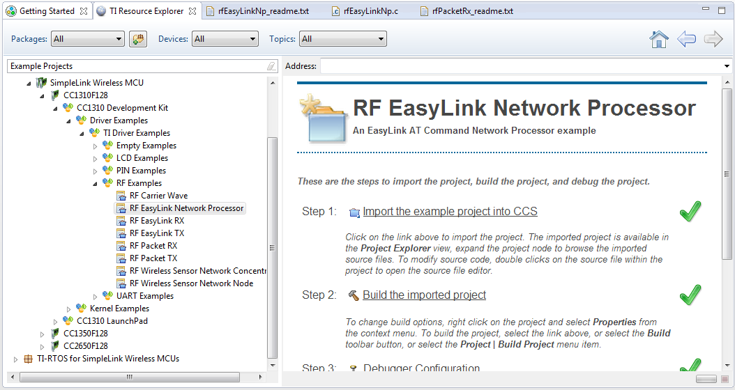
3. Expand the architecture so that you get down to the RF EasyLink Network Processor, as shown in the picture above.
4. Select the RF EasyLink Network Processor by clicking on it, then select "Import the example project into CCS".
Task 2: Building the EasyLink AT NWP Example
============================================
1. Connect your hardware, e.g. CC1310/CC1350 LaunchPad to your PC via USB.
The device will show up as two serial ports, use the COM port for the one with UART in the name.
2. Open the com port with a terminal program, e.g. Tera Term, use settings (115200 8N1)
3. Build and download the example by clicking the "Debug" button: (Shortcut F11)
[[y Large Build
First time you build it will take some time, the reason is that the TI-RTOS kernel is also built.
]]
4. Run the example by clicking on the play button.

5. You should now see "EasyLink" and some version information being printed on the serial port. The device is now ready to accept AT commands.
Task 3: Using the AT Command Interface to Configure RF Settings
======================================================================
[[b Team up!
For the remaining tasks, team up with another training attendee - you shall transmit data between each other. Make sure to use corresponding RF settings. Use the allocated channel/frequency from your instructor.
]]
The AT Command Interface uses ASCII characters so that a terminal emulator can send the commands, but also uses framing so that SW can format and parse the AT commands.
The frame format is shown below:
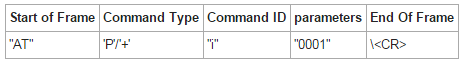
Here we use CR to represent Carriage Return or 0x0D.
When typing in the commands in terminal, press <kbd>ENTER</kbd> to execute. Avoid using backslash and similar keys as they can be interpreted as command characters".
Keep in mind that the EasyLink API is documented on this [wiki](https://processors.wiki.ti.com/index.php/SimpleLink-EasyLink)
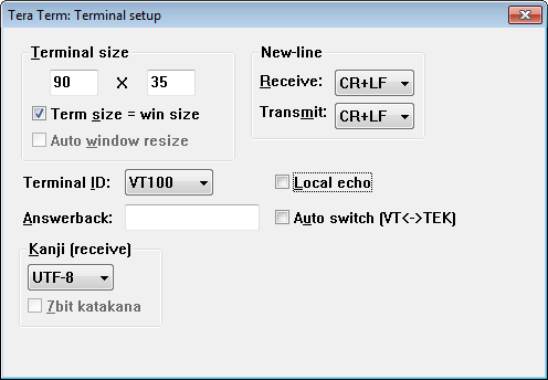
1. Open a terminal emulator such as putty or teraterm to the Com Port called ```Application/User UART```, with the settings shown below.
2. In order to initialize the radio to 2-GFSK 50kbps mode send the following command via the AT interface/serial port:
```c
AT+i 0
``` **AT+i** – Used to initialize the radio.
The possible values of the i/I command parameters are:
* 00: 2-GFSK, 50 kbps
* 01: For 625 bps Long Range Mode
* 02: For user defined from smartRF_settings.c/h
The device shall respond with "OK<CR>".
2. Set the frequency to your group's allocated frequency by sending (example for 868.0MHz)
```c
ATPFR=868000000
``` **ATPFR**: Used to set the communication frequency/channel of the radio.
The default frequency is 868.0 MHz
3. Find out what the output power is set to by sending
```c
ATPPW?
``` **ATPPW**: Used to set/get the radio output power.
The radio shall reply with configured output power setting.
[[b If +14 dBm (max) Output Power is required then you must make changes to ccfg.c to configure the DC/DC converter:
```c
#define CCFG_FORCE_VDDR_HH 0x1 //Force VDDR voltage to the factory HH setting (FCFG1..VDDR_TRIM_HH)
#include <startup_files/ccfg.c>
```
]]
Task 5: Exchanging Data between two Devices
==================================================
1. Put one device in RX mode:
```c
AT+RX
``` **AT+RX**: Used to set the radio in RX mode.
2. Send some data from the peer device:
```c
AT+TX Hello World!
``` **AT+TX**: Used to send data.
Task 6: Exchanging Data between a Device and SmartRF Studio
==================================================================
Next we will send packets from SmartRF Studio to another device running the EasyLink NWP example.
1. Put the device running EasyLink NWP in RX mode by sending:
```c
AT+RX
``` **AT+RX**: Used to set the radio in RX mode.
2. Open SmartRF Studio 7 version 2.4.0 or later
3. Connect the LaunchPad to the same (or another PC).
[[r Board already in use
If the debugger is currently in use, then a RED LED will light on the LaunchPad board. If one program is currently connected to an LaunchPad, then this has to be disconnected, or power cycled, before another program can connect to it.
]]
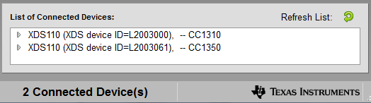
4. The devices should automatically show up in the device listing at the bottom. If not, click on the green arrow next to the **Refresh list**. If everything works and both boards are detected then you will see two boards in the device listing.
6. Double-click on one of the devices in the device listing and this should open up the Device Control Panel. You'll find the device serial number on the development kit.
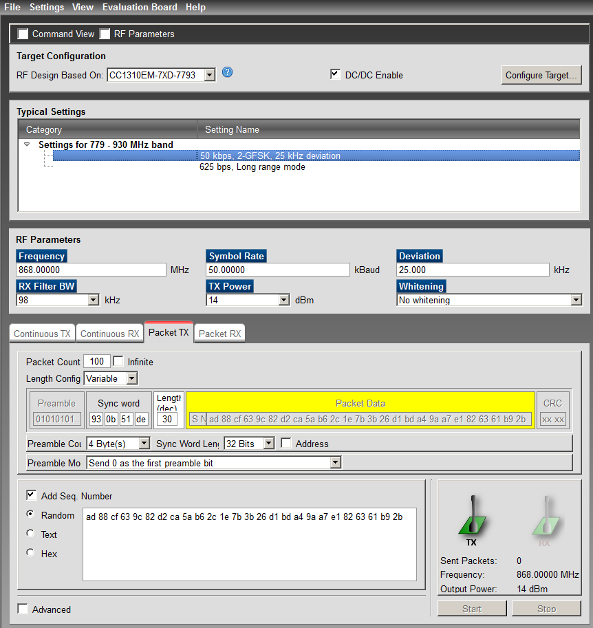
7. Make changes to the RF settings to match the ones you are using on your EasyLink device. You need to make sure you adhere to the EasyLink Frame format. Enable address (00 is default in EasyLink), send text (ASCII), and do not include a sequence number.
8. Click on the "Start" button in the "TX" tab to send data
9. Verify that you receive the sent data on the device running EasyLink NWP.
10. Do it the other way around; send data from your EasyLink device and receive it using SmartRF Studio.
Task 7: EasyLink Packet Error Rate (PER) test
====================================================
This task will be setting up an PER test between two devices (on two separate PCs) running the EasyLink NWP example.
The EasyLink AT interface supports the following test modes:
- Carrier Wave
- Modulated Signal
- PER TX
- PER RX
1. Start with initialising both devices to use 2-GFSK mode using:
```c
AT+i 0<CR>
``` **AT+i**: Used to initialize the radio.
PER Receiver
------------
1. Configure one device to be the PER receiver. This is enabled by setting test mode to 4. It will run for the number of packets configured in the `PP` parameter, or indefinitely if number of packets is set to 0.
To configure PER RX test mode to run for 100 packets:
```c
ATPPP=100<CR>
``` **ATPPP**: Read/Write number of PER TX/RX packets.
2. Set the device to PER RX by setting test mode to 4, do that by sending:
```c
ATPTM=4<CR>
``` **ATPTM**: Read/Write test mode.
The device enters RX and accepts 100 packets.
PER Transmitter
---------------
1. Configure the other device to be the PER transmitter. This is enabled by setting test mode to 3. It will run for the number of packets configured in the `PP` parameter, or indefinitely if the number of packets is set to 0.
To configure PER Tx test mode to run for 100 packets:
```c
ATPPP=100<CR>
``` **ATPPP**: Read/Write Number of PER Tx/Rx Packets.
2. Set the device to PER TX by setting test mode to 3:
```c
ATPTM=3<CR>
``` **ATPTM**: Read/Write test mode.
The device send 100 packets.
Running the PER Test
--------------------
While the test is running the below responses should be expected on the TX device:
TPER: 00
TPER: 01
TPER: 02
...
While the test is running the below responses should be expected on the RX device:
RPER: 00, 0001, 0000, -31
RPER: 01, 0002, 0000, -31
RPER: 02, 0003, 0000, -31
...
The columns are:
RPER: Sequence Number, Pass Count, Fail Count, RSSI
The sequence number is sent from the Tx PER, and is expected to increment by 1 in each packet. Pass Count increments every time a correct packet is received. Fail Count increments every time an incorrect packet is received.
Once the test completes the below response should be expected.
<RPER>: Done OK
Make some range testing, move around in the building to get some data points.
Bonus Tasks
==================================
For all bonus tasks you will need to rely more on the documentation than the previous tasks. The bonus tasks can be done in any order. There are also no solutions to the bonus tasks.
Bonus Task 8: Long Range Mode PHY
----------------------------------
Change PHY to use the Long Range Mode (LRM) - do some more PER testing. Does the range improve?
Bonus Task 9: Explore the AT Command Interface
----------------------------------
Explore what else you can realize by using the EasyLink AT command API. Keep in mind that the EasyLink API is documented on this [wiki](https://processors.wiki.ti.com/index.php/SimpleLink-EasyLink).
References
==================================
**TI-RTOS Kernel and Driver Documentation** – Available in the `doc` folder of the TI-RTOS installation root folder
**CC13xx TRM ** – Available at: [http://ti.com/lit/pdf/swcu117](http://ti.com/lit/pdf/swcu117).
**EasyLink API** – [Available at this wiki](https://processors.wiki.ti.com/index.php/SimpleLink-EasyLink).
**CC13xx Software Overview** – Available at: [https://www.ti.com/tool/cc13xx-sw](https://www.ti.com/tool/cc13xx-sw).