Introduction
==================================
This training will walk you through setting up the Wireless Sensor Network (WSN) example. When you have completed the training you will have a WSN consisting of a concentrator displaying data received from one or more sensor nodes.
The nodes will be truly ultra low power and only wake up to send data if the measured ADC value (capacitive coupling on certain pins) changes by a certain threshold.
This tutorial will take about 1 hour to complete and requires little knowledge except some basic familiarity with embedded programming.
This tutorial does not include any (or little) programming, it is simply a step by step instruction on how to get one of the provided TI-RTOS SimpleLink getting started examples running in Code Composer Studio.
For any questions you might have, please have a look at the E2E forum:
* [Sub-1 GHz E2E Forum (Public)](https://e2e.ti.com/support/wireless_connectivity)
WSN Concentrator
----------------
The WSN Concentrator example illustrates how to create a simple WSN Concentrator device which listens for packets from other nodes. This
example is meant to be used together with the WSN Node example to form a one-to-many network where the nodes send messages to the concentrator.
WSN Node
--------
The WSN Node example illustrates how to create a WSN Node device which sends packets to a concentrator. This example is
meant to be used together with the WSN concentrator example to form a many-to-one network where the nodes send messages to the concentrator.
Both the WSN concentrator and node example showcases the use of several Tasks, Semaphores and Events to get sensor updates and send packets with acknowledgement from the concentrator.
For the radio layer, the examples use the EasyLink API which provides an easy-to-use API for the most frequently used radio operations.
Prerequisites
==================================
[[b Allocated Frequency
If you are a part of a group training, please ask the instructor for a unique frequency to use for the duration of the training.
For simplicity, it is possible to use a base frequency (868.0, 915.0), allocate a number to everyone and then just multiply this with 100 kHz channel spacing. Participant number 5 would then use 868 + 0.1*5 = 868.5 MHz.
]]
Background
----------------
* Basic TI-RTOS and CCS knowledge.
* Attended or read through the CC13xx Proprietary Mode Deep-Dive documentation and/or presentation
Software
---------
The following software need to be installed prior to this training:
* [Code Composer Studio](https://www.ti.com/tool/ccstudio) 6.1 or higher **with latest updates**<br>
Make sure that CCS is using the latest updates: *Help* → *Check for Updates*
* [TI-RTOS](https://www.ti.com/tool/ti-rtos) 2.20.xx.xx or later
* [SmartRF™ Studio](https://www.ti.com/tool/smartrftm-studio) 2.4.x or later.
Hardware
---------
* 2 x CC1310 or CC1350 LaunchPads.
* 2 x USB Cables.
* 1 x 430BOOST-SHARP96 LCD panel.<br>
If you don't have an LCD: the rfWsnConcentrator provides output on the UART as well.
EasyLink API
==================================
The RF core has a dedicated driver called the TI-RTOS RF driver. This is used for all interaction with the RF core.
The EasyLink API is a simple abstraction layer on top of the RF Driver and is intended as a starting point for customers creating a proprietary Sub1-GHz protocol or application.
The API and examples are available in TI-RTOS for cc13xx/cc26xx MCU's version 2.20.xx.xx and later, which can be downloaded from [ti.com](https://software-dl.ti.com/dsps/dsps_public_sw/sdo_sb/targetcontent/tirtos/index.html)
For instructions on using the TI-RTOS examples refer to `C:\TI\tirtos_cc13xx_cc26xx_<version>\docs\Getting_Started_Guide_cc13xx_cc26xx.pdf`.
The EasyLink Example can be found in the resource explorer under **SimpleLink Wireless MCU**->**CC1310F128**->**CC1310 Development Kit**->**Driver Examples**->**TI Driver Examples**->**RF Examples**:
* RF EasyLink Tx
* RF EasyLink Rx
* RF EasyLink Network Processor
* RF Wireless Sensor Network Concentrator
* RF Wireless Sensor Network Node
The EasyLink API is documented and maintained on this [wiki](https://processors.wiki.ti.com/index.php/SimpleLink-EasyLink).
[[y Note
The EasyLink layer does not support any regional RF conformance such as Listen Before Talk required for the license free frequency band.
Customers need to add support for the regional conformance that their product requires under the EasyLink API.
]]
Generic API function | Description
-----------------------|----------------------------------------------------
EasyLink_init() | Inits and opens the RF driver
EasyLink_transmit() | Blocking transmit
EasyLink_transmitAsync()| Nonblocking transmit
EasyLink_receive() | Blocking receive
EasyLink_receiveAsync()| Non-blocking receive
EasyLink_abort() | Aborts a non-blocking call
EasyLink_GetIeeeAddr() | Gets the IEEE address
EasyLink_EnableRxAddrFilter() | Enables/disables RX filtering on the address
EasyLink_SetFreq() | Sets the frequency
EasyLink_GetFreq() | Gets the frequency
EasyLink_SetRfPwr() | Sets the TX power
EasyLink_GetRfPwr() | Gets the TX power
EasyLink_getAbsTime() | Gets the absolute radio time
EasyLink_setCtrl() | Sets advanced configuration options
EasyLink_getCtrl() | Gets advanced configuration options
Task 1: Importing the WSN Examples
==================================
In this task we will use Code Composer Studio (CCS) to import the WSN Concentrator example.
[[b Using IAR Embedded Workbench to import Examples
It is also possible to use IAR EW to import all TI-RTOS SimpleLink bundled examples. In order to do so follow the guide located here:
* [TI Processors wiki](https://processors.wiki.ti.com/index.php?title=Creating_TI-RTOS_Applications_in_IAR_Embedded_Workbench)
]]
Importing and Building the RF Wireless Sensor Network Concentrator Example
--------------------------------------------------------------------------
1. Open CCS 6.1 or later
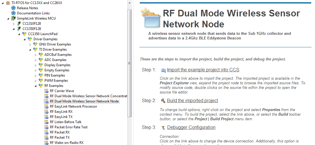
2. Click "Browse examples" in the Getting Started pane. This will open up the Resource Explorer;
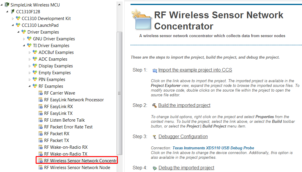
3. Expand the architecture so that you get down to the RF Wireless Sensor Network Concentrator, as shown in the picture above.
4. Select the RF Wireless Sensor Network Concentrator by clicking on it, then select "Import the example project into CCS".
5. Connect you CC13xx LaunchPad to you PC via USB.
6. Build and download the example by clicking the "Debug" button: (Shortcut F11)
[[y Large Build
First time you build it will take some time, the reason is that the TI-RTOS kernel is also built.
]]
7. Run the example by clicking on the play button.

8. You should now see "Waiting for node" on the 430BOOST-SHARP96 LCD.
9. Unplug your Concentrator device and continue with the tutorial.
Importing and Building the RF Wireless Sensor Network Node Example
------------------------------------------------------------------
1. Open the Resource Explorer in CCS.
2. Expand the architecture so that you get down to the RF Wireless Sensor Network Node.
4. Select the RF Wireless Sensor Network Node by clicking on it, then select "Import the example project into CCS".
5. Connect another LaunchPad to your PC via USB.
6. Build and download the example by clicking "Debug" (shortcut F11)
[[y Several LaunchPads connected
In order to be certain you flash the right board, it is suggested that you disconnect the Concentrator board while flashing the Node board.
]]
7. Run the example by clicking on the play button.
Task 2 – Putting it all to work
=====================================
1. Power on your concentrator device
2. Power on your node device(s)
3. You shall now see node data (raw ADC value) being displayed on the concentrator LCD from all nodes once data is updated locally. Press and hold the left side button on the node device (marked BTN-1), the character on the LCD on the consentrator device should change from "0" to "1" under SW column.
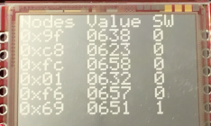
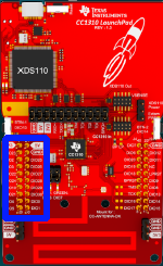
4. The ADC is connected to the DIO26 pin on the node device. Cover the left side pins with your finger (see pins marked in blue below) and observe a change in node value on the concentrator device.
Task 3: Change RF Channel
================================
The default frequency is 868 MHz. In order to avoid interference form other devices on your joint training session it can be useful to change RF channel. Here is how you do it!
1. Open the file "RadioProtocol.h" in your CCS editor.
2. Change the RADIO_FREQUENCY to your wanted setting.
```c
#define RADIO_FREQUENCY 868000000
``` **RADIO_FREQUENCY** used to select RF channel/frequency.
3. Build and download, make sure to make the changes on both your concentrator and node devices.
Task 4: Switch from 2-GFSK 50 kbps to Long Range Mode (LRM)
===========================================================
Since the EasyLink layer supports different PHY settings it is straight forward to change the WSN example to use LRM instead.
1. Open the file "RadioProtocol.h" in your CCS editor.
2. Change the RADIO_EASYLINK_MODULATION to your wanted setting.
```c
#define RADIO_EASYLINK_MODULATION EasyLink_Phy_50kbps2gfsk
``` **RADIO_EASYLINK_MODULATION** used to select RF PHY settings.
The EasyLink_Phy_50kbps2gfsk is a enum defined in EasyLink.h:
```c
/// \brief Phy Type passed to EasyLink_init
typedef enum
{
EasyLink_Phy_50kbps2gfsk = 0, ///Phy settings for 50kbps data rate, IEEE 802.15.4g GFSK.
EasyLink_Phy_625bpsLrm = 1, ///Phy settings for 625bps data rate, Long Range Mode.
EasyLink_Phy_Custom = 2, ///Customer Phy specific settings exported from SmartRF Studio
} EasyLink_PhyType;
``` **EasyLink_PhyType** used to select RF PHY settings.
3. Build and download, be sure to make the changes on both your concentrator and node devices.
Task 5: Measure Power consumption on the node
=============================================
The node is entering the lowest possible power mode between measurements - let's measure its average power consumption.
1. Connect an ampere meter between pin3V3 and pinGND on your node device.
2. Power on the node device.
Task 6: Modify Code Running on the Sensor Controller
============================================================
The WSN node example includes code for the sensor controller, in this task we shall modify the interval for reading the ADC.
1. Make sure [Sensor Controller Studio](https://www.ti.com/tool/sensor-controller-studio) is installed on your system.
2. In your imported WSN node example, open the adc_sample.scp file from within Sensor Controller Studio by selecting "Open an existing project". The file is located in the **sce** folder.
3. Click on the execution code, in to pane to the right.
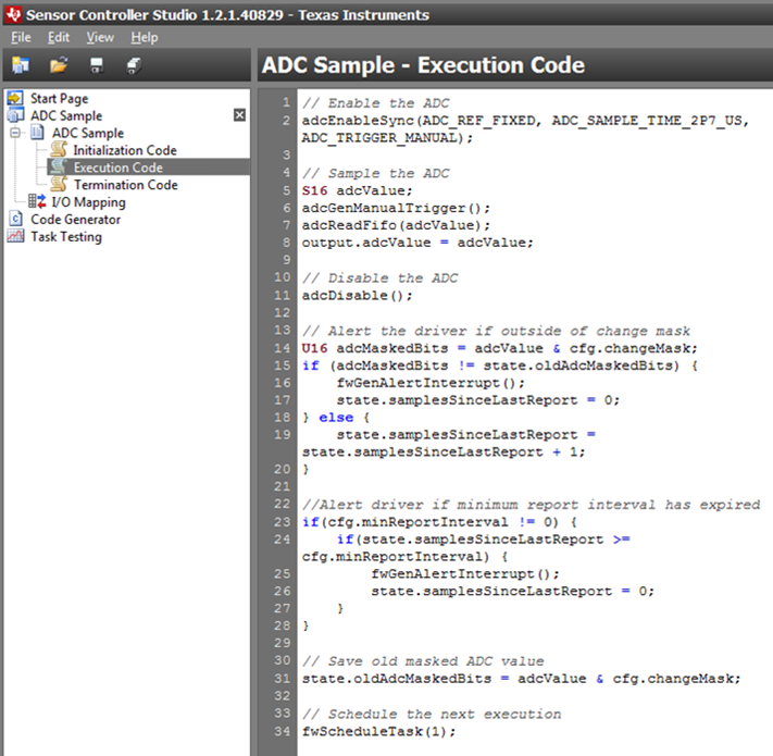
4. Modify the last line to:
fwScheduleTask(2);
...to make the next wake schedule every 2 tics.
5. Click on Code Generator in the right pane.
6. Click on the button on the bottom of the page saying "Generate driver source code":
7. Switch back to CCS, rebuild and run.
8. Measure average power consumption to see if is lower. We are now reading the sensor every 2 seconds instead of 1.
Task 7: Add a Dual Mode Sensor Node
============================================================
The CC1350 device is a dual band device that supports both sub-1GHz and Bluetooth Low Energy (BLE). In this task we will add node(s) that, in addition to sending sub-1GHz sensor data, also sends BLE advertisement packets (BLE beacons)!
Those BLE beacons can be picked up by any BLE capable device.
[[b This step requires additional CC1350LP HW
]]
1. Follow the same procedure as in Task 1 to import the CC1350LP rfWsnDmNode example into your CCS workspace. This can be found under CC1350F128->CC1350 LaunchPad->TI Driver Examples->RF Examples:
2. Make the same changes to frequency and phy mode as you did in Task 3 and 4.
3. Follow the same procedure as in Task 1 to build and debug the rfWsnDmNode example on a CC1350LP.
4. Once the rfWsnDmNode examples is running on the CC1350LP you should see it appear on the CC1310LP Concentrator's LCD and UART.
Task 8: Observe the Dual Mode Sub1-GHz and BLE features of the CC1350 device using the TI SmartPhone App
============================================================
1. On a BLE enabled SmartPhone open app store or google play and search for "TI SimpleLink Starter" and install the TI SimpleLink Starter application.
2. Open the TI SimpleLink Starter application, you should see the CC1350 LP appear in the list of devices. Press button BTN-1 on the CC1350LP and observe the "Button Pressed" in the Smart Phone application and on the Sub1Ghz Wsn Concentrators LCD.
3. The TI SmartPhone application uses Manufacturer Specific BLE Advertisements to advertise the device and the state of the button. If you have an LCD Booster Pack fitted you will see that the BLE Advertisement mode is set to "BLE MS + URL". This can also be seen on the UART if you do not have an LCD Booster pack. This means that the CC1350 is advertising both the Manufacturer Specific format and the Eddystone URL format advertisements. The Eddystone URL advertisement beacon is use for the Physical Web. Visit the links below to learn more about the Physical Web:
https://www.youtube.com/embed/1yaLPRgtlR0
https://google.github.io/physical-web/
4. Enable your SmartPhone to display the Eddystone URL by following these instructions below. Once completed open the URL advertised by the CC1350 Wsn Node.
https://support.google.com/chrome/answer/6239299?hl=en
5. Observe the other beacon formats supported. This can be done by pressing button BTN-2 to cycle through the other advertisement formats supported. This can be done by pressing button BTN-2 to cycle through the other advertisement formats supported, the advertisement mode used can be seen on the LCD and UART:
- URL: This is the Eddystone URL beacon (as discussed previously used for Physical Web) interleaved with Telemetry data.
- UUID: This is used for Locationing and is also interleaved with Telemetry data.
* There are a number of applications that can be used to display Eddystone beacons. Some do not show the telemetry data, we have tested this with the Estimote Android Application which can be used to display the Telemetry data. The Telemetry Beacon include data for:
- Temperature
- Battery level
- On time
- Packet Count
[[b The rfWsnDmConcentrator running on a CC1350LP can also be used to beacon Node data by using BTN-1 to select the Node and BTN-2 to cycle through the Beacon formats. The rfWsnDMCncentrator defaults to not sending beacons.
]]
References
==================================
**TI-RTOS Kernel and Driver Documentation** – Available in the `doc` folder of the TI-RTOS installation root folder
**CC13xx Radio TRM Chapter**: [https://www.ti.com/lit/swcu117](https://www.ti.com/lit/swcu117)
**EasyLink API** – Doxygen available, ask your trainer.
**CC13xx Software Overview** – Available at: [https://www.ti.com/tool/cc13xx-sw](https://www.ti.com/tool/cc13xx-sw).