Introduction
==================================
The purpose of this exercise is to familiarize the users with the RF driver, Code Composer Studio and SmartRF™ Studio; by importing and modifying an existing RX/TX example application.
**Task 1**: Send and receive packets with SmartRF Studio.
**Task 2**: Import and modify an existing RX example with Code Composer Studio.
**Task 3**: Export RF settings from SmartRF Studio to Code Composer Studio example application.
**Task 4**: Import and modify an existing RX example with Code Composer Studio.
**Task 5**: Test two 13xx LaunchPads with the flashed TX and RX firmware.
For any questions you might have, please have a look at the E2E forum:
* [Sub-1 GHz E2E Forum (Public)](https://e2e.ti.com/support/wireless_connectivity)
Prerequisites
==================================
[[b Allocated frequency
If you are part of a group training, please ask the instructor for a unique frequency to use for the duration.
For simplicity, it is possible to use a base frequency (868.0, 915.0), allocated a number to everyone and then just multiply this with 100 kHz channel spacing. Participant number 5 would then use 868 + 0.1*5 = 868.5 MHz.
]]
Background
----------------
* Basic TI-RTOS and CCS knowledge
* Some basic familiarity with embedded programming.
Software
---------
* [Code Composer Studio](https://www.ti.com/tool/ccstudio) 6.1 or higher **with latest updates**<br>
Make sure that CCS is using the latest updates: *Help* → *Check for Updates*
* [TI-RTOS](https://www.ti.com/tool/ti-rtos) 2.20.xx.xx or later
* [SmartRF Studio](https://www.ti.com/tool/smartrftm-studio) 2.4.x or later.
Hardware
---------
* 2 x CC1310 or CC1350 LaunchPads
* 2 x USB Cables
Documentation, SmartRF™ Studio and Code Export
==================================
This _hands-on_ introduces SmartRF Studio and explains the basic usage of the TI-RTOS RF driver.
Documentation
-----------------
The main documentation related to the RF core is in the [Technical Reference Manual]. It contains detailed information about the CC1310 and how to use the peripheral units. Chapter 23 focuses on the radio core and is recommended to read before this training.
SmartRF™ Studio
-----------------
SmartRF Studio is used to test and evaluate RF settings on the CC13xx.
It can also send and receive packets when connected to a device.
SmartRF Studio uses radio operation commands as described in section 23.7 of the [Technical Reference Manual].
For example, if we send one single packet in SmartRF studio (don't worry, you'll learn how to do this later) then the content of the Command View will look like the below image.
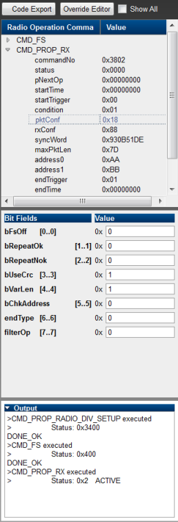
In the bottom part of this picture we can see exactly which commands were sent. In the top view we can explore the content of those commands.
Please note that the content of the command in the top view correlate exactly to that of the documentation. If you click on a specific field, then even the bit fields are shown and easy to edit.
Code Export
-----------------
In order to use a RF configuration in a TI-RTOS application, the settings must be exported as command structures into C code.
This is done via the _Code Export_ button in SmartRF Studio.
**SmartRF Studio Code Export**
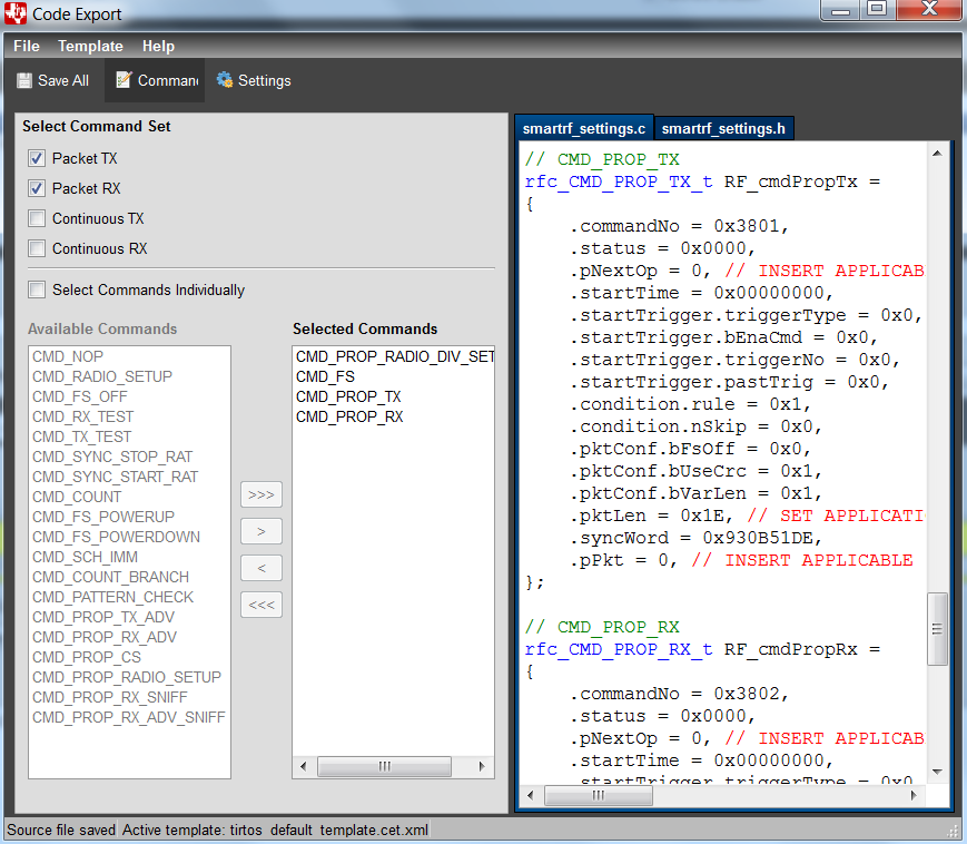
The exported code can then be used directly in any TI-RTOS project. In the _rfPacketTx_ example that we discuss throughout this _hands-on_, the exported settings are found in `smartrf_settings/smartrf_settings.h/c`. These structs contain additional, application-specific fields such as triggers and pointers to the actual data. These need to be set in the application source code.
Summary
-----------------
* The [Technical Reference Manual] describes radio operation commands.
* SmartRF Studio can be used to configure, test and export them as C structs.
* The TI-RTOS application overwrites application-specific command fields and executes the commands using the RF driver.
TI-RTOS RF Driver
==================================
In a TI-RTOS application, the RF core is accessed exclusively via the RF driver.
It provides functions to set up the RF core and to execute various radio commands which are divided into three groups:
* Immediate commands
* Direct commands
* Radio operation commands
Immediate and direct commands execute immediately and return a result upon completion.
They are protocol-independent and often used to configure the RF core and to interact with running radio operation commands.
Radio operation commands, in contrast, are more complex.
They support various triggers may also be connected towards sophisticated chains.
In this tutorial, we will only use radio operation commands.
API
-----------------
The RF driver documentation is installed as part of TI-RTOS. To access it, please refer to your TI-RTOS installation folder. If you chose default settings during the installation process, then it will look like:
`[drive]:/TI/tirtos_cc13xx_cc26xx_2_xx_xx_xx/products/tidrivers_cc13xx_cc26xx_2_xx_xx_xx/docs/doxygen/html/index.html`
The documentation is also available on the [TI website][TI-RTOS Drivers API] (TI-RTOS release 2.20).
For convenience, we repeat it briefly here:
API function | Description
----------------------|----------------------------------------------------
RF_open() | Open client connection to RF driver and return a command handle
RF_close() | Close client connection to RF driver
RF_postCmd() | Execute a radio operation command asynchronously or append it to the command queue if another command is already running
RF_pendCmd() | Wait for previously posted command to complete
RF_runCmd() | Execute a radio operation command synchronously and wait for its completion
RF_cancelCmd() | Abort a currently running command
RF_flushCmd() | Abort a currently running command and clear the command queue
RF_runDirectCmd() | Execute a direct command synchronously
RF_runImmediateCmd() | Execute an immediate command synchronously
Task 1: SmartRF Studio ↔ SmartRF Studio
==================================
SmartRF Studio can be used to test RF settings and to evaluate those settings by sending and receiving packets.
This task will take you through the process of testing a complete TX / RX link by sending packets between two CC13xx LaunchPads using only SmartRF Studio. No additional software is needed.
Connecting SmartRF Studio
----------------------------------
1. Open SmartRF Studio 7 version 2.4.x or later
2. Make sure that both LaunchPads are connected and powered on. Also make sure that no other program, such as CCS or a serial port monitor, is currently accessing any of the development kits.
<br>The green LED should now light up to indicate that the kit is on.
3. The devices should automatically show up in the device listing at the bottom. If not, click on the green arrow next to the **Refresh list**. If everything works and both boards are detected then you will see two boards in the device listing.

4. Double-click on one of the devices in the device listing and this should open up the Device Control Panel.

5. Navigate back to the SmartRF Studio main window and double click on the other device as well. The one that is connected will say **DC-Panel Open**, so double-click on the other one.
6. Congratulations! You have successfully connected SmartRF Studio to two different targets. You see one main SmartRF Studio window as well as two Device Control Panel windows.
Configuring RX and TX
----------------------------------
### PHY Modes
For the CC13xx devices, Texas instruments has characterized different RF modes which are also referred to as a _PHY_. That is:
* default mode, 50 kbps using a generic FSK modulation scheme,
* long-range mode, 625 bps, using a spread spectrum scheme,
* high-speed mode, 4 Mbps.
The 50 kbps mode is selected as default.
### Packet format
The RF core on the CC13xx provides a flexible packet engine which allows to:
* adjust length and content for both, preamble and syncword,
* use packets with fixed or variable length (through a length field),
* apply address filters to the packet (after the length byte),
* configure a CRC check.
| Preamble | Sync word | Length | Payload | CRC
--------|------------|-------------|----------|----------------------|
Size | 4 bytes | 4 bytes | 1 byte | N bytes | 2 bytes
Content | 0x55555555 | 0x930b51de | 125 byte | Application specific | 0xXXYY
SmartRF Studio inserts a 2 byte sequence number as the first two bytes of the payload. This is optional and is used to calculate the Packet Error Rate, PER. The rest of the payload consists of random data.
### Apply the settings
Next we will configure one SmartRF Studio in RX and the other in TX.
1. Both of the open Device Control Panels should already be in the **Packet TX** tab. This tab is used to transmit packet using the selected typical setting.
[[y Change Frequency
If in a group, before doing anything else, remember to change to your allocated frequency.
]]
2. In one of the Device Control Panels, switch to the **Packet RX** tab and press the **Start** button. This will set up the device in RX mode.
3. Next switch back to the first window, that is still in the **Packet TX** tab, and press **Start**. This will cause the device to send 100 packets.
4. If you switch back to the Device Control Panel that is in RX then you should see packets coming in.
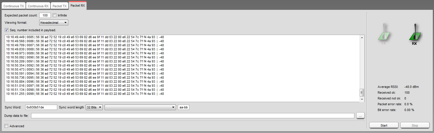
On the right side in the **Packet RX** tab it is possible to see:
* The average RSSI.
* How many packets was received OK / Not OK.
* The PER (Packet Error Rate) and BER (Bit Error Rate).
Task 2: Import a CC13xx Project in CCS
======================================
The installed TI-RTOS drivers and example code is supported by Code Composer Studio (including CCS Cloud), IAR Embedded Workbench and GCC.
In this task we will use Code Composer Studio to import and modify an existing CC13xx project with the exported settings generated in SmartRF Studio.
Import an Existing Example Project
----------------------------------
Follow these steps to import an existing example for Code Composer Studio called rfPacketTx.
1. Click on the drop down menu **View** → **Resource Explorer(examples)**
2. Expand the elements: **TI-RTOS for CC13XX and CC26xx** → **SimpleLink Wireless MCU** → **CC1310F128** → **CC1310 Launchpad** → **Driver Example** → **TI Driver Example** → **RF Examples**
3. Select **RF Packet TX**.
4. Your view should now be:

5. Click **Import the example project into CCS**.
6. There should now be a new project in the Project Explorer called **rfPacketTx_CC1310_LAUNCHXL_TI_CC1310F128**:

7. You have now imported the rfPacketTx example project.
8. To build it, right click on the project in the Resource Explorer and press **Build Project**.
9. If everything works, you should see **\*\*\*\* Build Finished \*\*\*\*** in the **Console** tab.
LaunchPad XDS110 Emulator Setup CCS
-----------------------------------
The Launchpads contain an emulator called XDS110.
In these tasks we are going to use two LaunchPads with CCS, one for Tx and one for Rx.
Follow these steps to specify an XDS110 emulator to a specific project, thus avoiding the system to be confused when two emulators are connected.
1. Connect the first LaunchPad (now flashed with rfPacketTx) to your PC, make sure no other emulators are connected.
2. Start SmartRF studio

3. In the startup window, make a note of the **XDS Device ID**

4. Go back to the **Project Explorer** in CCS, **rfPacketTx**.
5. Expand the folder **targetConfigs**
6. Double click on the **CC13xxF128.ccxml** file

7. Click on **Target configuration**:

8. Click on **Texas Instruments XDS110 USB Debug Probe** → **Select by serial number**:

9. Enter the **serial number** from step 3.
10. Click on **Save**
11. The rfPacketTx example is now configured to only use this particular emulator. Hence you neeed not to worry about connecting other targets.
Repeat this exercise for the second board in task 4 (rfPacketRx)
Run and Debug the Project
----------------------------------
The rfPacketTx example illustrates how to do simple packet transmission using the TI-RTOS RF driver.
This example is meant to be used in cooperation either with the rfPacketRx example or with SmartRF Studio.
For every packet transmitted, the green LED (DI07) is toggled.
Next we will run and debug the project.
1. Go to **Run** → **Debug**
By default this will:
* Open the CCS Debug view
* Build the project if there has been any changes
* Flash the target
* Halt at the beginning of `main()`
2. To run the program, press the **Resume** button in the debug toolbar or **Run** → **Resume** (F8).

3. The green LED (DI07) on the LaunchPad toggles when data is transmitted over the RF interface.
To stop, simply press the **Terminate** button in the same toolbar, or from the **Run** drop down menu. This will automatically return to the Edit view.
Task 3: Firmware TX → SmartRF RX
==================================
In this task you will use SmartRF Studio to export settings in order to receive packets from the rfPacketTx application.
Export RF settings from SmartRF Studio
----------------------------------
SmartRF Studio can be used to generate radio operation commands for use with the RF driver. This makes it easy to set up PHY settings in studio and then export that exact setting to be used in your application.
First: The rfPacketTx/Rx examples allready contains such SmartRF_settings with the following defaults.<br>
**Description** | **Default value**
----------------------------|-----------------------
Address | aa-bb
Frequency | 868.00000 MHz
Data Format | Serial mode disable
Deviation | 25.000 kHz
Packet Length Config | Variable
Max Packet Length | 128
Packet Length | 30
RX Filter BW | 98 kHz
Symbol Rate | 50.00000 kBaud
Sync Word Length | 32 Bits
TX Power | 14 dBm
Whitening | No whitening
In this task we will increase the symbol rate from 50 kbps to 100 kbps. This requires the modification of other settings as well.
To export the new settings from SmartRF Studio, follow these steps:
1. Open up SmartRF Studio and double-click on the CC1310 or CC1350.
[[b Offline Mode
It is possible to open the Device Control Panel even if no device is connected. This is perfect for exporting settings even if you do not want to connect SmartRF Studio to the device.
]]
2. Enable the **Command View** by checking the **Command View** check box at the top. This will open a new view on the right.
This view lists all radio commands needed to set up **Packet RX** / **Packet TX** depending on the view you are in.

3. In the section **Typical Settings**, double-click on **50 kbps, 2-GFSK, 25 KHz deviation**
<br>
This is to ensure that you start with the recommended settings most close to the ones we are implementing in this task.
4. In the **RF Parameters** section, type in **100** in the **Symbol Rate** text box, **50** in the **Deviation** text box and choose **196 KHz** from the **RX Filter BW** drop down box.

[[y Change Frequency
If in a group, remember to change to your allocated frequency.
]]
5. Click on the **Code Export** button at the top of the new **Command View**:

6. In the newly opened **Code Export** window, press the **Commands** button in the middle.
This view shows which radio commands that is going to be exported. By default all commands needed for RX and TX are exported.<br>The commands needed are:
* CMD_PROP_RADIO_DIV_SETUP
* CMD_FS
* CMD_PROP_TX
* CMD_PROP_RX
These are enough for this workshop.

7. Two files are generated based on your settings in SmartRF Studio 7: First time use: **untitled.c** and **untitled.h**.
8. The rfPacketTx example already contains the files above.<br>
In CCS, delete the two files from the existing rfPacketTx project:<br>

When the files are deleted, go back to SmartRF Studio, select the **untitled.h** tab and press **File** → **Save as** → **smartrf_settings.h**<br>Click on the **untitled.c** tab, choose **File** from the drop down menu and choose **Save As** → **smartrf_settings.c**.
Note: the above order in important to get the correct <code>#include</code> in **smartrf_settings.c**.
The files must be saved in the **smartrf_settings** folder:<br>
`...\workspace_v6_1\rfPacketTx_CC1310_LAUNCHXL_TI_CC1310F128\smartrf_settings`
9. The PHY settings are now exported to CCS and your modified rfPacketTx example is ready to be build and debugged again.
10. Test the application by compiling and running a debug session.
A good indication that the code works is that the green LED (DIO7) still blinks. <br>Next we will use SmartRF Studio to receive packets.
Setting up SmartRF Studio for RX
----------------------------------
Next we will use SmartRF Studio to receive packets you are sending.
1. Start up a SmartRF Studio instance and connect to the CC13xx that is currently not used for TX.
2. To set up SmartRF studio according to the TX settings, repeat step 3, 4 and 5 in Task 3<br>
If you changed your frequency in step 5, task 3, do so accordingly as well.
2. Go to the **Packet RX** tab and do the following:
* Change the **Expected packet count** by checking the **Infinite** check-box
* **Viewing format: Hexadecimal**
3. Press the **Start** button.
4. Now you should receive a message with the text generated by the rfPacketTx code every time the RED LED (DIO6) toggles.

Task 4: SmartRF Studio TX → Firmware RX
==================================
In this task we will use CCS to import (as in task2), modify (as in task 3) and build an existing rfPacketRx example.
The Packet RX example illustrates how to do simple packet RX using the TI-RTOS RF driver.<br>
This example is meant to be used with the Packet TX example or SmartRF Studio.<br>
For every packet received, the red LED (DI06) is toggled.<br>
The frequency and other RF settings can be modified using SmartRF Studio.
Import and modify an existing example project
----------------------------------
Your task is to import the example as you did in **Task 2** for the **rfPacketTx** example.
1. Follow each step in Task 2, but choose the example **rfPacketRx**.
2. Follow each step in task 3 for the **rfPacketRx** example.
Setting up SmartRF Studio for TX
----------------------------------
Next we will send packets from SmartRF Studio for the firmware to receive.
1. Start up a SmartRF Studio instance and connect to the CC13xx that is currently not is use for RX.
2. Choose the same settings as before for the **RF Parameters**.
2. Go to the **Packet TX** tab and press **Start**
3. If everything works the red LED on the CC13xxLP running the RX code should now blink for every packet received.
Task 5: Firmware TX → Firmware RX
==================================
In this task we will compile and flash the two CC13xx Launchpad (LP) with the RX code from Task 4 and the other with the TX code from Task 3.
If you just completed Task 4, then simply shut down SmartRF Studio and turn off the LP used for RX as we only need to set up the LP used for TX.
1. In the Project explorer of CCS, click on the rfPacketTx
2. Start debugging to flash the LP with the TX code.
3. If you need to re-flash the other LP for RX, click on the rfPacketRx in Project Explorer of CCS.
4. Start debugging to flash the LP with the RX code.
5. Stop all debugging, disconnect and reconnect the boards.
6. The green LED on the TX board should blink indicating transmission of an packet, and the red LED on the RX board should blink as packets are received.
References
==================================
**TI-RTOS Kernel and Driver Documentation** – Available in the `doc` folder of the TI-RTOS installation root folder. It is also available online: [TI-RTOS 2.20 Drivers API][TI-RTOS Drivers API].
**CC13xx Radio TRM Chapter** – Provided as a part of this training
**CC13xx Software Overview** – Available at: [https://www.ti.com/tool/cc13xx-sw](https://www.ti.com/tool/cc13xx-sw).
**Technical Reference Manual** – Available on the [TI Website][Technical Reference Manual]
<!-- Definition of inline references -->
[Technical Reference Manual]: https://www.ti.com/lit/swcu117
[TI-RTOS Drivers API]: https://software-dl.ti.com/dsps/dsps_public_sw/sdo_sb/targetcontent/tirtos/2_20_00_06/exports/tirtos_full_2_20_00_06/products/tidrivers_cc13xx_cc26xx_2_20_00_08/docs/doxygen/html/index.html