Introduction
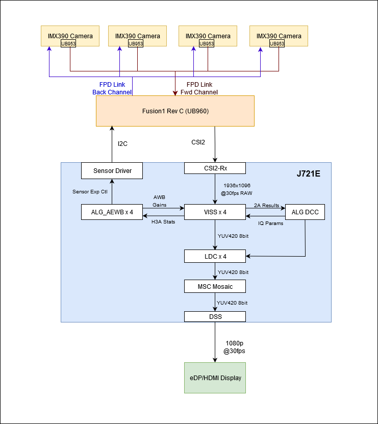
This application demonstrates the use of VISS node and TI's 2A (AE & AWB) algorithm in multi-channel mode. The dataflow is
- Configure image sensors using sensor driver f/w APIs
- Acquire RAW images from camera sensors
- Process the images on VISS
- Run AE (Auto Exposure) and AWB (AutoWhiteBalance) algorithms, using H3A output from VISS
- Run LDC on the output of VISS
- Scale LDC output using MSC and arrange in a mosaic
- Display the mosaic using Display Sub-System
Any number of cameras from 1-8 (up to 12 with J784S4 + Fusion2 board) can be selected by the user, subject to constraints of sensor driver. The application assumes that all cameras are identical.
Supported plaforms
| Platform | Linux x86_64 | Linux+RTOS mode | QNX+RTOS mode | SoC |
| Support | NO | YES | YES | J721e / J721S2 / J722S / J784S4 / J742S2 |
Data flow (RAW12 input)
Steps to run the application on J7 EVM (Linux + RTOS mode)
- Build the application and related libraries as mentioned in Build Instructions for Linux+RTOS mode
- Connect up to 8 D3-IMX390 RCM camera modules to cam0 - cam7 ports of the Fusion1 board.
- See Fusion1 Board setup
- Use the is_interactive flag to run the demo in an interactive mode which allows the user to print performance characteristics on the UART console.
- Run the app as shown below
cd /opt/vision_apps
source ./vision_apps_init.sh
./run_app_multi_cam.sh
- The processed output for one of the captured channel is displayed through DSS on HDMI or eDP display - Display interface selection through compile time setting in the file platform/j721e/rtos/common/app_cfg_mcu2_0.h
- See Vision Apps Datasheet for performance of 8 camera system
Steps to run the application on J7 EVM (QNX + RTOS mode)
- Build the application and related libraries as mentioned in Build Instructions for QNX+RTOS mode
- Connect up to 8 D3-IMX390 RCM camera modules to cam0 - cam7 ports of the Fusion1 board.
- See Fusion1 Board setup
- Use the is_interactive flag to run the demo in an interactive mode which allows the user to print performance characteristics on the UART console.
- In the case of J784S4, use the bypass_split_graph flag to determine whether or not to use both VPAC's available on J784S4. The split configuration mode splits the output from the capture node into 2 parallel pipelines running on each VPAC instance. The pipelines merge together in the mosaic node and are rendered onto the display using the display node. For other SoC's, this configuration is also enabled by default, but it will only execute on a single VPAC.
- Run the app as shown below
cd /ti_fs/vision_apps
. ./vision_apps_init.sh
./run_app_multi_cam.sh
- The processed output for one of the captured channel is displayed through DSS on HDMI or eDP display - Display interface selection through compile time setting in the file platform/j721e/rtos/common/app_cfg_mcu2_0.h
- See Vision Apps Datasheet for performance of 8 camera system


 1.8.14