7. CCS Setup for J721E
Code Composer Studio is an integrated development environment (IDE) that supports TI’s Micro controller and Embedded Processors portfolio. It provides useful tools to develop and debug embedded applications.
Please visit Code Composer Studio product (https://www.ti.com/tool/ccstudio) for more information.
Important
Below screen shots and examples show paths and instructions for Linux. The same applies for Windows except use Windows file/folder paths instead.
In Linux+RTOS mode, SPL/uboot bootloader loads the R5F, C6x, C7x, A72 binaries
CCS is needed to debug the software on R5F, C6x, C7x (and A72 when in RTOS mode).
In RTOS only mode, CCS is needed to load and run the binaries on different CPU cores in the SoC.
The CCS emulation pack and CSP (Chip Support Package) needs to be downloaded separately.
7.1. CPU names used in PSDK RTOS vs CCS
Below table shows the mapping of names in PSDK RTOS and CCS
CPU name in PSDK RTOS |
CPU name in CCS |
|---|---|
mcu1_0 / mcu1_1 |
MCU_Cortex_R5_0 / MCU_Cortex_R5_1 |
mcu2_0 / mcu2_1 |
MAIN_Cortex_R5_0_0 / MAIN_Cortex_R5_0_1 |
mcu3_0 / mcu3_1 |
MAIN_Cortex_R5_1_0 / MAIN_Cortex_R5_1_1 |
mpu1 |
CortexA72_0_0 |
c6x_1 |
C66xx_0 |
c6x_2 |
C66xx_1 |
c7x_1 |
C71x_0 |
7.2. Step 1: Install CCS
Install CCS v12.4 : CCS can be downloaded from https://www.ti.com/tool/download/CCSTUDIO/12.4.0
CCS installation details are available on https://dr-download.ti.com/software-development/ide-configuration-compiler-or-debugger/MD-J1VdearkvK/12.4.0/CCS_12.4.0_ReleaseNotes.htm
This release is tested on below CCS version 12.4.0.00007
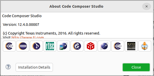
Fig. 7.1 CCS: IDE version
During installation, there is a ‘Setup’ step where you can select components. Be sure to select: “TDAx Driver Assistance SoCs & Jacinto DRAx Infotainment SoCs” as shown below:
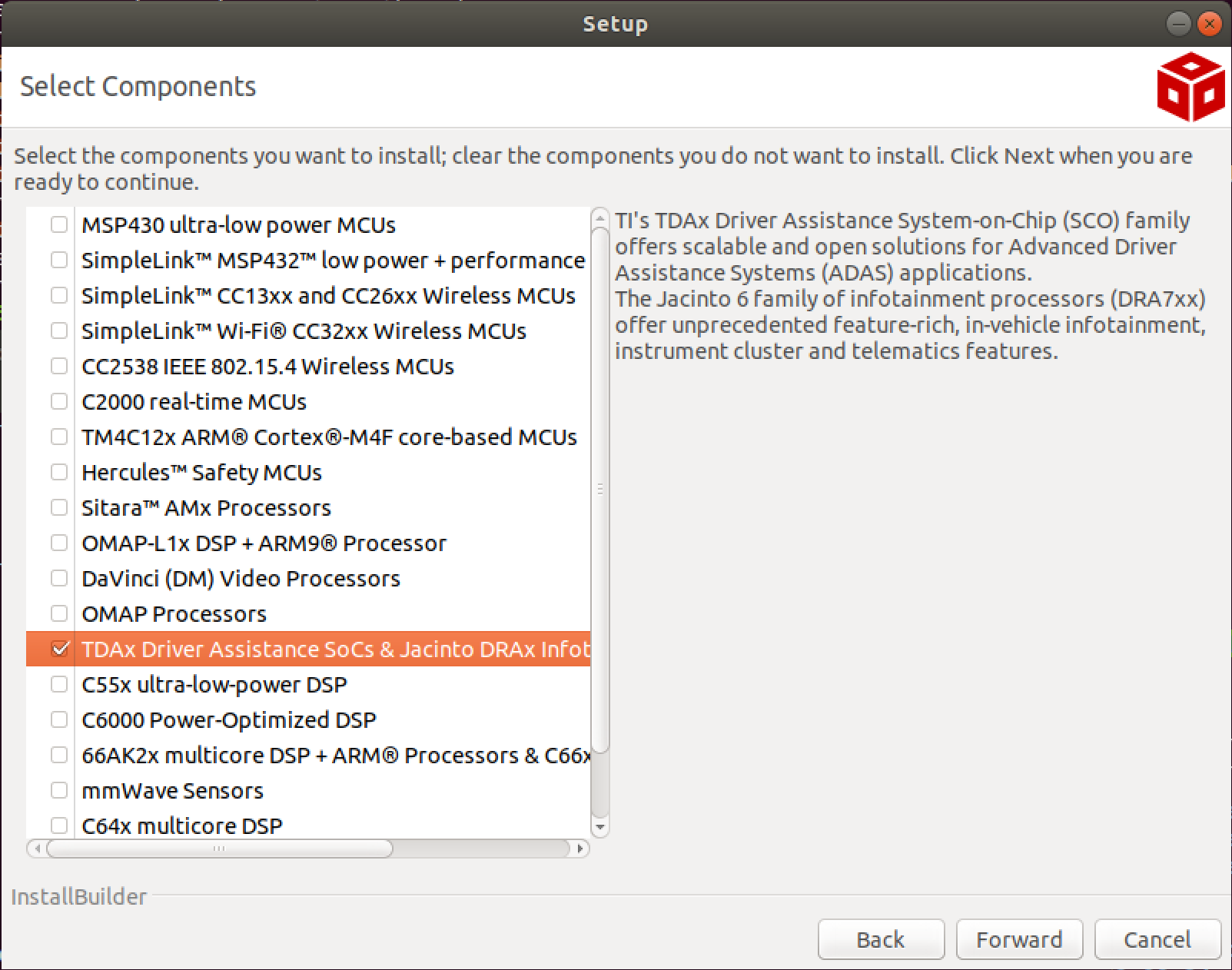
Fig. 7.2 CCS: Download Components
Here after we’ll be referring to the CCS installation directory as ${CCS_INSTALL_PATH}
In Linux, this will be
${HOME}/ti/ccsv1240/ccs
In Windows, this will be
C:\\ti\\ccsv1240\\ccs\
7.3. Debugging without HLOS running on A72 (RTOS-only / baremetal)
Important
This section is applicable only if you are loading an RTOS only application. To debug using CCS when Linux/QNX runs A72, refer section Debugging with HLOS running on A72 (Linux / QNX).
7.3.1. Step 2: Setup CCS target configuration and GELs files
Create a CCS target config, you can name it J721E_EVM.ccxml.
In Code Composer Studio, go to the File menu and select New -> Target Configuration File
Name the Target Configuration file as J721E_EVM.ccxml and click Finish
Select Connection as Texas Instruments XDS110 USB Debug Probe, if you are using on board debugger (J3 usb connector)
Select Connection as Spectrum Digital XDS560V2 STM USB Emulator, if you are using Spectrum digital XDS560 USB debugger connected to JTAG Mipi connector (J16)
Select the Board as J721E_DRA829_TDA4VM shown below
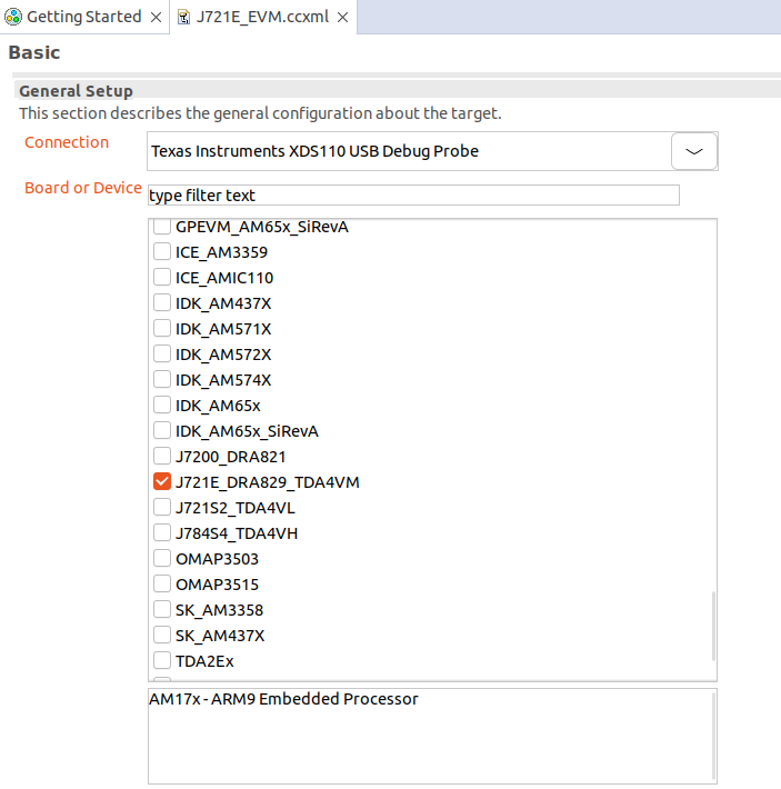
Fig. 7.3 CCS: Target Configuration
Load the initialization script of the DMSC_Cortex_M3_0 core with the J7 Gels as shown below.
Open the Advanced tab of the target configuration file J721E_EVM.ccxml
Gel files can be found at below path
${CCS_INSTALL_PATH}/ccs_base/emulation/gel/J721E_DRA829_TDA4VM/gel/J721E.gel
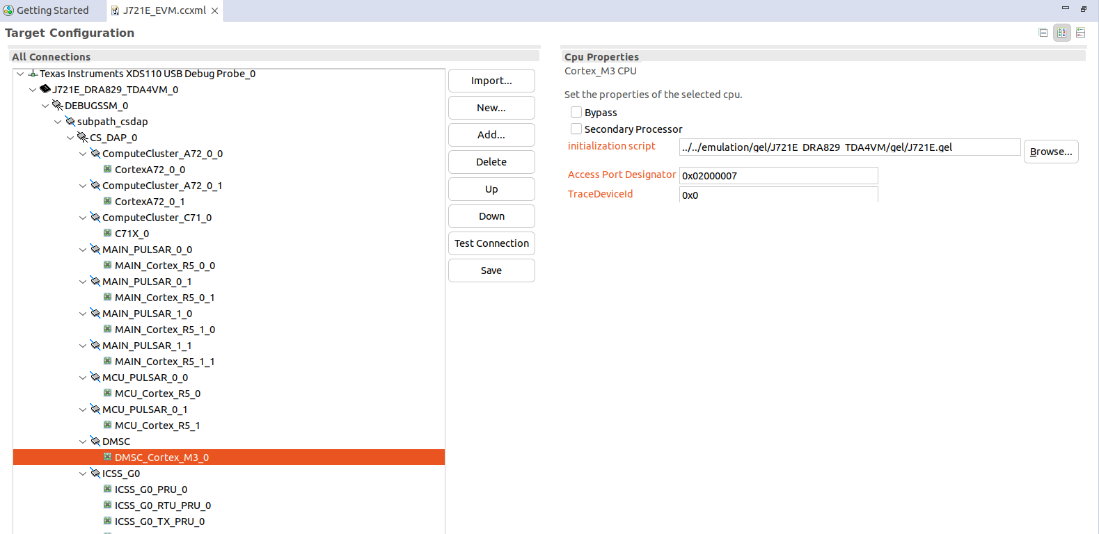
Fig. 7.4 CCS: Target Configuration Initialization Script
7.3.2. Step 3: Load RTOS/baremetal application binaries thru CCS
Note
When using CCS boot flow, please configure EVM in NOBOOT mode ( see No Boot Mode ) for connecting and loading binaries via CCS.
The launch.js file below is responsible to load and run the DMSC. It is also responsible to set the board configuration input for the DMSC. The board configuration is passed by the PDK example ${PSDK_RTOS_PATH}/pdk_jacinto_{version}/packages/ti/drv/sciclient/examples/sciclient_ccs_init executing on the MCU R5F core. The default board configuration is available for reference at ${PSDK_RTOS_PATH}/pdk_jacinto_{version}/packages/ti/drv/sciclient/soc/V1/sciclient_defaultBoardcfg.c
All PDK and SDK examples require the DMSC firmware to be executed.
Starting SDK 7.1, the launch.js file is also responsible to load the ${PSDK_RTOS_PATH}/pdk_jacinto_{version}/packages/ti/drv/sciclient/examples/sciserver_testapp which is used to service the RM and PM services on MCU1_0. Refer MCU1_0 Application Development with SYSFW for details. The sciserver_testapp is a simple RTOS based application which runs the Sciserver used to service RM and PM requests from cores other than MCU1_0.
For applications developed and debugged on MCU1_0 application one can disable loading the Sciserver_testapp by setting the loadSciserverFlag to 0. Please do go through the MCU1_0 Application Development with SYSFW page for details on what libraries should be linked on the MCU1_0 application to run RM and PM services.
GEL initialization
Open the launch.js script in an editor. Script is present in below path:
${PSDK_RTOS_PATH}/pdk_jacinto_{version}/packages/ti/drv/sciclient/tools/ccsLoadDmsc/j721e/launch.js
${PSDK_RTOS_PATH} is the path to your PSDK RTOS installation, for example:
/ti/ti-processor-sdk-rtos-j721e-evm-xx_xx_xx_xx
Edit the variable “pdkPath” with the absolute path of the pdk package, i.e ${PSDK_RTOS_PATH}/pdk_jacinto_{version}/packages
Open Code Composer Studio and launch the Target Configuration previously setup
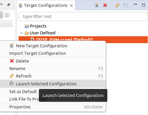
Fig. 7.5 CCS: Launch CCS Target Configuration
Go to the View Target configurations and launch a target configuration is done by right clicking on it.
Open the scripting console in CCS - Go to the View menu and then select Scripting Console
Load the launch.js script as shown below.
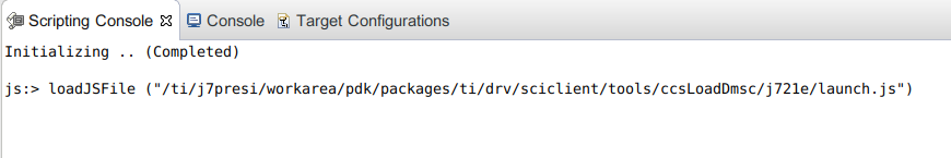
Fig. 7.6 CCS: Launch script
Wait till the script finishes. This step can take considerable time as it configures PLL etc. in the SOC via GEL files and configures DDR. This will connect to the MCU_Cortex_R5_0 core.
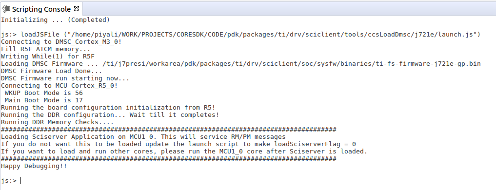
Fig. 7.7 CCS: Scripting Console Output
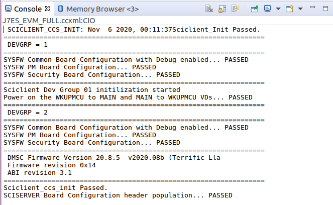
Fig. 7.8 CCS: Console Output
After script completes execution you should see below in Debug window
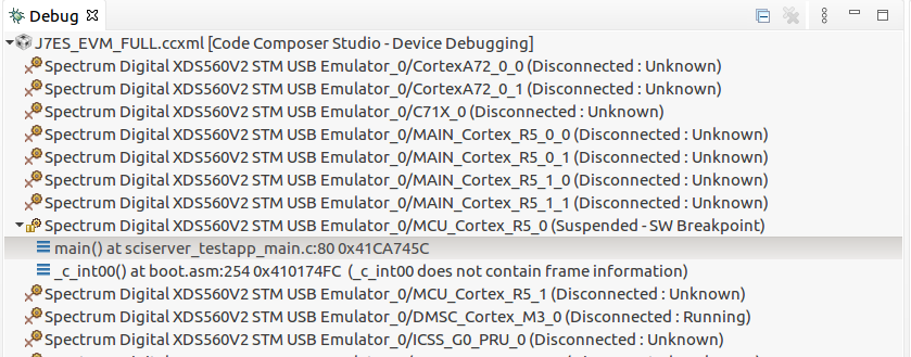
Fig. 7.9 CCS: Launch script Complete
Load and run the binaries in CCS. Debug as usual using CCS.
Now you can connect to any core and load the corresponding application binaries.
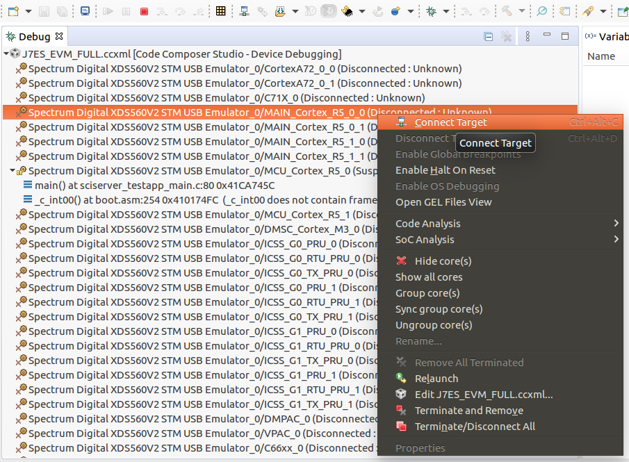
Fig. 7.10 CCS: Loading the demo application binary
Go to the Run menu and then select Load -> Select Program to Load
In the Load Program window, browse to application binary you want to load.
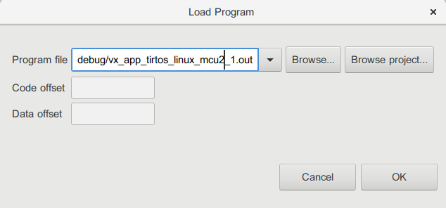
Fig. 7.11 CCS: Loading the demo application binary
Go to the Run menu and then select Resume to start executing demo binary.
7.4. Debugging with HLOS running on A72 (Linux / QNX)
Important
This section is applicable only if you are loading a HLOS (Linux or QNX) application. To debug RTOS cores using CCS when not running Linux or QNX on A72, refer section Debugging without HLOS running on A72 (RTOS-only / baremetal).
CCS cannot be used to debug applications on the A72. For Linux, it is recommended to use gdb which comes preinstalled on the filesystem. For QNX, it is recommended to use QNX Momentics.
7.4.1. Step 4: Setup CCS target configuration
Install CCS, CCS emulation packs and the CSP as per Step 1: Install CCS.
Create a CCS target config, you can name it “J721E_EVM_NO_GEL.ccxml”.
Select Connection as Texas Instruments XDS110 USB Debug Probe, if you are using on board debugger (J3 usb connector)
Select Connection as Spectrum Digital XDS560V2 STM USB Emulator, if you are using Spectrum digital XDS560 USB debugger connected to JTAG Mipi connector (J16)
Select the Board as EVM_J721E shown below
Fig. 7.12 CCS: Target Configuration
Remove the gel file path (....emulationgelJ721E_DRA829_TDA4VMgelJ721E.gel) from DMSC cortex M3 settings
7.4.2. Step 5: Load RTOS core firmware symbols thru CCS
Load the debug version of the firmware binaries on the HLOS file system, and boot device.
Launch the target config file created
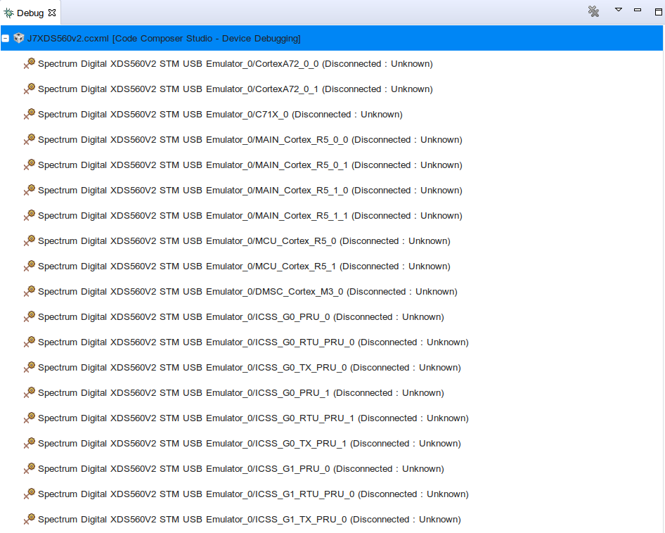
Fig. 7.13 CCS: Target Configuration launched
Now you can connect to the required non-A72 core (i.e R5, C66xx_0 etc) and load the symbols of the application binary.
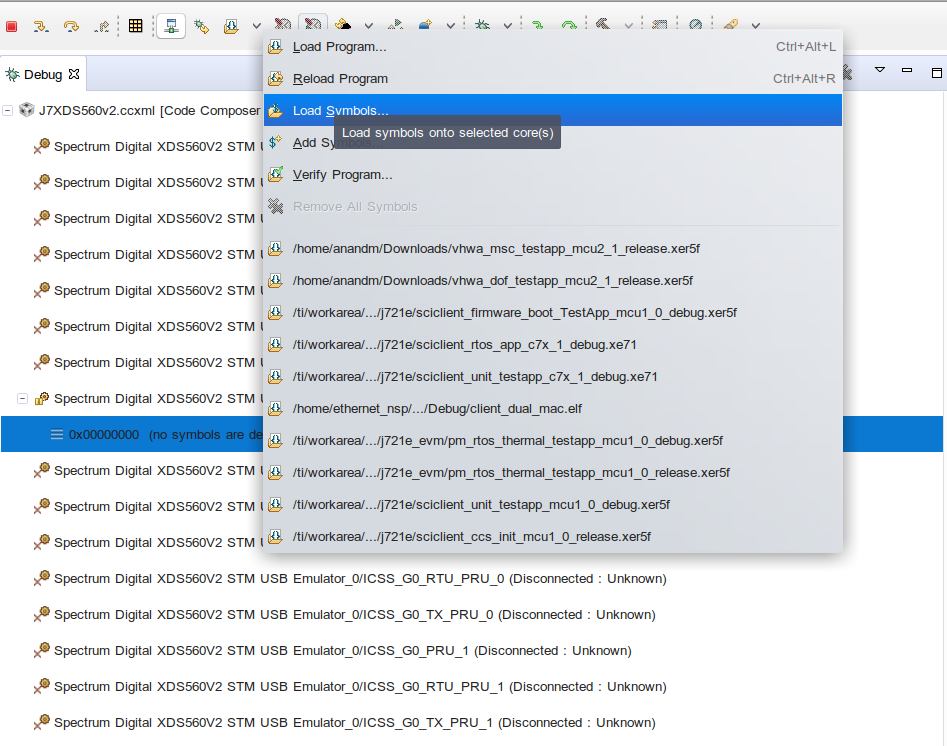
Fig. 7.14 CCS: Load symbols in the connected non-A72 core
Now you can put breakpoints wherever required and debug as usual.