Vision Apps User Guide
Multi-chip Video-Capture Application using PCIe Backplane

Introduction

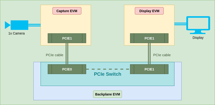
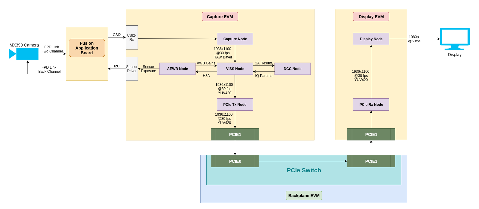
This application demonstrates the feature of PCIe backplane. The PCIe backplane acts as a PCIe switch and allows peers connected to backplane (via PCIe), to communicate with each other. To demonstrate the communication, we have three EVMs connected using PCIe. One of the EVMs is running real-time camera application, capturing frames. These frames are sent via the second EVM (Backplane EVM) to the third EVM, which receives the frame and renders it to display. The backplane EVM is switching the data completely in hardware without any software involvement.

Supported plaforms

Platform Linux+RTOS mode SoC
Support YES J721e

Supported image sensors

Sensor Data Format Resolution Frame Rate
IMX390 Bayer RAW12 HDR 1936x1096 30

Block Diagram

app_pcie_video_block_diagram.png

Data flow

app_pcie_video_data_flow.png

Hardware Setup

Hardware Requirements

  1. Three J721e EVMs
  2. Two PCIe Cables. For more details about cables, refer to Hardware Setup Details section here.
  3. Fusion Application Board
  4. IMX390 Sensor, FPD Link cable
  5. eDP Display, eDP cable
    Note
    You can also use HDMI display. You will need an Infotainment Expansion Board Kit for the same.

Steps to connect the EVMs

  1. The naming convention for EVMs is as under:
    1. Capture EVM: The one to which camera is connected
    2. Display EVM: The one to which display is connected
    3. Backplane EVM: The one to which Capture EVM and Display EVM are connected using PCIe
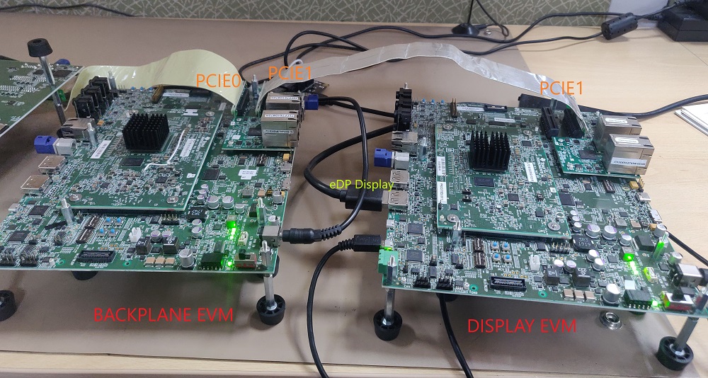
  2. Use the PCIE0 and PCIE1 slots for Backplane EVM
  3. Use the PCIE1 slot for Capture and Display EVM
  4. Connect eDP Display to Display EVM
  5. Connect Fusion Application Board to Capture EVM
  6. Connect Camera module to the "Cam 0" Port on Fusion Application Board

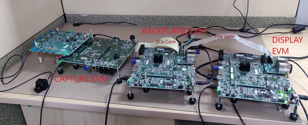
Following are some photos for reference:

app_pcie_video_hw_setup_1.jpg
app_pcie_video_hw_setup_2.jpg
app_pcie_video_hw_setup_3.jpg
app_pcie_video_hw_setup_4.jpg

Steps to run the application

  1. Build the application and related libraries as mentioned in Build Instructions. You can avoid this step if you are using the pre-built SDK package.
  2. Three SD cards are needed to be prepared for three EVMs. They can be created by following the steps mentioned in Run Instructions.
  3. Apply k3-j721e-pcie-backplane.dtbo overlay to the Backplane EVM. Refer the following page for instructions on how to apply the overlay: ${PSDKLA_PATH}/docs/linux/How_to_Guides/Target/How_to_Change_dtb_File.html . ${PSDKLA_PATH} refers to the path where Processor SDK Linux Automotive (PSDKLA) is installed.
  4. Boot only the Backplane EVM first. Run the following steps on the Linux console:
    mount -t configfs none /sys/kernel/config
    cd /sys/kernel/config/pci_ep/
    mkdir functions/pci_epf_test/func2
    echo 0x104c > functions/pci_epf_test/func2/vendorid
    echo 0xb00d > functions/pci_epf_test/func2/deviceid
    echo 2 > functions/pci_epf_test/func2/msi_interrupts
    echo 2 > functions/pci_epf_test/func2/msix_interrupts
    ln -s functions/pci_epf_test/func2 controllers/d000000.pcie-ep/
    mkdir functions/pci_epf_test/func3
    echo 0x104c > functions/pci_epf_test/func3/vendorid
    echo 0xb00d > functions/pci_epf_test/func3/deviceid
    echo 2 > functions/pci_epf_test/func3/msi_interrupts
    echo 2 > functions/pci_epf_test/func3/msix_interrupts
    ln -s functions/pci_epf_test/func3 controllers/d000000.pcie-ep/
    mkdir functions/pci_epf_test/func4
    echo 0x104c > functions/pci_epf_test/func4/vendorid
    echo 0xb00d > functions/pci_epf_test/func4/deviceid
    echo 2 > functions/pci_epf_test/func4/msi_interrupts
    echo 2 > functions/pci_epf_test/func4/msix_interrupts
    ln -s functions/pci_epf_test/func4 controllers/d000000.pcie-ep/
    mkdir functions/pci_epf_test/func5
    echo 0x104c > functions/pci_epf_test/func5/vendorid
    echo 0xb00d > functions/pci_epf_test/func5/deviceid
    echo 2 > functions/pci_epf_test/func5/msi_interrupts
    echo 2 > functions/pci_epf_test/func5/msix_interrupts
    ln -s functions/pci_epf_test/func5 controllers/d000000.pcie-ep/
    mkdir functions/pci_epf_test/func6
    echo 0x104c > functions/pci_epf_test/func6/vendorid
    echo 0xb00d > functions/pci_epf_test/func6/deviceid
    echo 2 > functions/pci_epf_test/func6/msi_interrupts
    echo 2 > functions/pci_epf_test/func6/msix_interrupts
    ln -s functions/pci_epf_test/func6 controllers/d000000.pcie-ep/
    echo 1 > controllers/d000000.pcie-ep/start
    mkdir functions/pci_epf_test/func2_1
    echo 0x104c > functions/pci_epf_test/func2_1/vendorid
    echo 0xb00d > functions/pci_epf_test/func2_1/deviceid
    echo 2 > functions/pci_epf_test/func2_1/msi_interrupts
    echo 2 > functions/pci_epf_test/func2_1/msix_interrupts
    ln -s functions/pci_epf_test/func2_1 controllers/d800000.pcie-ep/
    mkdir functions/pci_epf_test/func3_1
    echo 0x104c > functions/pci_epf_test/func3_1/vendorid
    echo 0xb00d > functions/pci_epf_test/func3_1/deviceid
    echo 2 > functions/pci_epf_test/func3_1/msi_interrupts
    echo 2 > functions/pci_epf_test/func3_1/msix_interrupts
    ln -s functions/pci_epf_test/func3_1 controllers/d800000.pcie-ep/
    mkdir functions/pci_epf_test/func4_1
    echo 0x104c > functions/pci_epf_test/func4_1/vendorid
    echo 0xb00d > functions/pci_epf_test/func4_1/deviceid
    echo 2 > functions/pci_epf_test/func4_1/msi_interrupts
    echo 2 > functions/pci_epf_test/func4_1/msix_interrupts
    ln -s functions/pci_epf_test/func4_1 controllers/d800000.pcie-ep/
    mkdir functions/pci_epf_test/func5_1
    echo 0x104c > functions/pci_epf_test/func5_1/vendorid
    echo 0xb00d > functions/pci_epf_test/func5_1/deviceid
    echo 2 > functions/pci_epf_test/func5_1/msi_interrupts
    echo 2 > functions/pci_epf_test/func5_1/msix_interrupts
    ln -s functions/pci_epf_test/func5_1 controllers/d800000.pcie-ep/
    mkdir functions/pci_epf_test/func6_1
    echo 0x104c > functions/pci_epf_test/func6_1/vendorid
    echo 0xb00d > functions/pci_epf_test/func6_1/deviceid
    echo 2 > functions/pci_epf_test/func6_1/msi_interrupts
    echo 2 > functions/pci_epf_test/func6_1/msix_interrupts
    ln -s functions/pci_epf_test/func6_1 controllers/d800000.pcie-ep/
    echo 1 > controllers/d800000.pcie-ep/start
  5. Now boot the Display and Capture EVMs
  6. Run the following instructions on Capture and Display EVM respectively to setup the PCIe link between peers. (No strict ordering required to run these steps on Capture and Display EVMs)
    1. Capture EVM:
      # Since the same vendor ID and device ID are used for multiple function
      # drivers (pci-endpoint-test and ntb_hw_epf), the device should be first
      # unbound from existing driver, and then bound to ntb_hw_epf
      echo 0001:01:00.0 > /sys/bus/pci/devices/0001\:01\:00.0/driver/unbind
      echo 0001:01:00.0 > /sys/bus/pci/drivers/ntb_hw_epf/bind
      # Install the kernel driver which sets up PCIe region adress mappings
      modprobe ntb_peer local_shmem_address=0xadfe0020 local_buffer_address=0xadfe0000 local_buffer_size=0x00000100 inbound_mw_address=0x80000000 inbound_mw_size=0x40000000
    2. Display EVM:
      # Since the same vendor ID and device ID are used for multiple function
      # drivers (pci-endpoint-test and ntb_hw_epf), the device should be first
      # unbound from existing driver, and then bound to ntb_hw_epf
      echo 0001:01:00.0 > /sys/bus/pci/devices/0001\:01\:00.0/driver/unbind
      echo 0001:01:00.0 > /sys/bus/pci/drivers/ntb_hw_epf/bind
      # Install the kernel driver which sets up PCIe region adress mappings
      modprobe ntb_peer local_shmem_address=0xadfe0000 local_buffer_address=0xae000000 local_buffer_size=0x20000000 inbound_mw_address=0x80000000 inbound_mw_size=0x40000000
  7. There are app_pcie_video_source.cfg and app_pcie_video_sink.cfg files in "/opt/vision_apps/" folder on the rootfs partition, where few parameters can be configured. Unless they are modified, default parameters will be used.
  8. Run the applications as shown below:
    1. Capture EVM:
      ./run_app_pcie_video_source.sh
    2. Display EVM:
      ./run_app_pcie_video_sink.sh
  9. The output is displayed through DSS on eDP or HDMI display connected to Display EVM. Default display interface is eDP. Display interface can be selected through compile time setting in the file apps/basic_demos/app_tirtos/common/app_cfg_mcu2_1.h