Gateway is one of the major use cases in modern cars. Performance requirements for gateway applications are ever increasing due to the advanced connected car architecture having multiple domain controllers. The CAN-Ethernet gateway demo showcases P2P (Protocol to Protocol) translation i.e. translating data and control information between incompatible networks like Ethernet and CAN for communication on the J721E device through the IEEE-1722 protocol.
The demo application enables full duplex routing between: CAN-to-Ethernet, Ethernet-to-CAN, CAN-to-CAN, and Ethernet-to-Ethernet. The demo uses MCAL drivers running on one Main R5F core, along with a Ethernet remote switch server running on the other Main R5F.
Note : The document still refers to j721e/J721E in many places where folder paths are mentioned, please replace with j7200/J7200 as needed for DRA821.
Before getting into more details, readers should familiarize themselves with the assumptions made in this document and general demo requirements.
This document refers to three types of demos
Root access is required because the demo uses raw sockets, and raw sockets are only accessible with root privileges.
Ubuntu 18.04 is required if user intends to run the GUI which is provided as a precompiled binary.
Code Composer Studio (CCS) version 9.3.0 and above
PC Ethernet tools - Required for receiving and transmitting data over Ethernet
Use/run recv_1722.out and send_1722.out utilities on host PC. These utilities are available at
<SDK_INSTALL_PATH>/gateway-demos/pctools
Test Automation Framework - Can only be used with PCAN-USB tool and Ethernet adapters attached to Linux PC
run_demo.py to run automation tools. There is a separate section on using the test automation framework below.CAN tool software (PCAN drivers and PCAN View if using PCAN-USB tool) for regular demo and low latency demo.
PCAN Driver 8.9.3 for Linux (if using the test automation framework) from PEAK-System Technik GmbH for regular demo. See Download Link https://www.peak-system.com/fileadmin/media/linux/files/peak-linux-driver-8.9.3.tar.gz
For Out of Box configuration CAN software is not required.
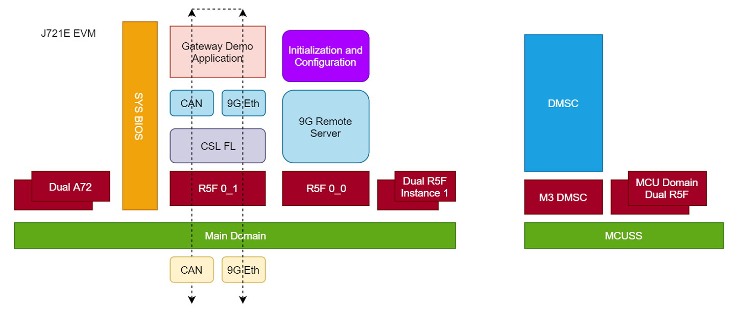
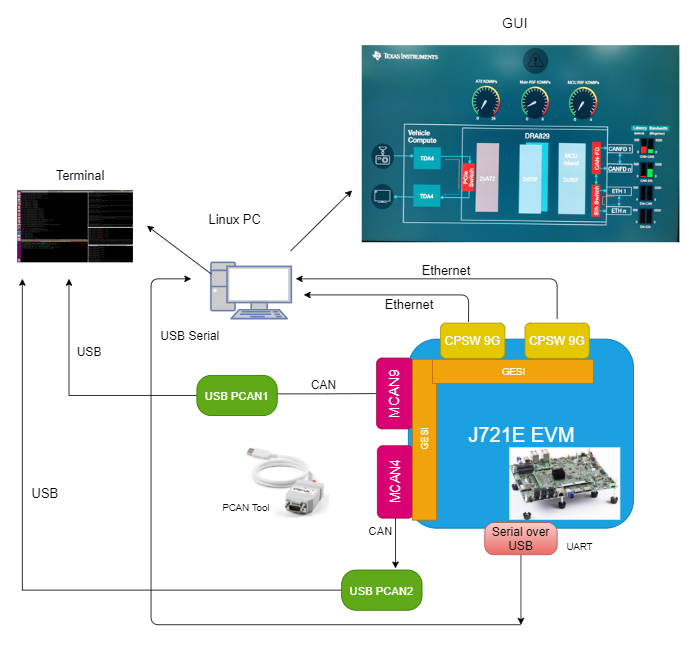
The following block diagram shows the various functional blocks and the data flow used in the gateway demo application. As shown in the diagram, PC Ethernet applications are used for transmitting and receiving Ethernet frames between PC and the J721E/J7200 EVM. Similarly, any compatible CAN tool can be used for CAN message reception and transmission.
The routing is done based on a queue-based architecture, where the gateway task periodically polls the CAN and Ethernet queues, which are, in turn, populated by the respective drivers in the interrupt context. This architecture allows full packet inspection of packet and allows matching two asynchronous interfaces like Ethernet and CAN.
The CAN/Ethernet demo application is supported only on the Main_Cortex_R5_0_1 core of the Jacinto device along with the accompanying remote switch driver, which runs on the Main_Cortex_R5_0_0 core.
The CAN_ETH Gateway demo is located in the Processor SDK RTOS release under the following directory path
<SDK_INSTALL_PATH>/gateway-demos
This contains two folders :
Users must run either the can_traffic_generator app or the default sciclient test application for regular demo. For Out of Box configuration, users must run the can_traffic_generator application.
User must issue make command from <SDK_INSTALL_PATH>/gateway-demos location. Detailed description of other directories is given below:
RTOS components:
Processor SDK RTOS drivers:
can_eth_gateway_app and can_traffic_generator_app) are built using makefile. The low latency demo is also built using the can_traffic_generator_app command but with an additional macro LOW_LATENCY_DEMORefer to PDK rules.mk for setting tools paths. Run following commands after this has been done.
Type the following in <SDK_INSTALL_PATH>/gateway-demos to see makefile options:
make help
The following are steps to clean the demo and delete both applications:
  cd <SDK_INSTALL_PATH>/gateway-demos
  make allclean
The following are steps to compile the can_eth_gateway_app with all dependencies for J7200:
  cd <SDK_INSTALL_PATH>/gateway-demos
  make -s can_eth_gateway_app BOARD=j7200_evm
This will generate binaries for both CAN Eth Gateway application (under <SDK_INSTALL_PATH>/gateway-demos/binary) and EthFw application (under <SDK_INSTALL_PATH>/ethfw/out)
The following are steps to compile the can_traffic_generator_app with all dependencies for J721E:
  cd <SDK_INSTALL_PATH>/gateway-demos
  make -s can_traffic_generator_app BOARD=j721e_evm CORE=mcu1_0
To compile the Low latency demo, uncomment line #81 in can_traffic_generator/makefile to enable the macro LOW_LATENCY_DEMO and repeat the step above.
If you are building the applications for the first time or after a clean build then all PDK dependencies are built first. For can_eth_gateway_app MCU2_1 dependencies get built
and for can_traffic_generator_app MCU1_0 dependencies.
If that doesn't happen then you will get a build error during linking.
If you see this issue, please build the dependencies first. For eg. for can_eth_gateway_app use the command (for J7200)
make -s depend_can_eth_gateway BOARD_SUPPORT=j7200_evm
For can_traffic_generator_app use the command (for J721E)
make -s depend_can_generator BOARD_SUPPORT=j721e_evm
The PC tools for Ethernet reception, transmission and Test Automation are located under pctools directory. These tools can be built only for Linux:
cd <SDK_INSTALL_PATH>/gateway-demos/pctools
make all
The python scripts can be used without any changes. Usage is described below under "Test Automation Framework"
The regular demo can be run either using the Automated Test Framework or manually. The Automated Test Framework has the limitation that it can only be used with the PCAN-USB tool from PEAK-System Technik GmbH.
If using a CAN tool from another manufacturer, please refer to the section which describes how to manually run the demo. The setup for both the systems looks the same, so it is described below before we discuss the Automated Test Framework.
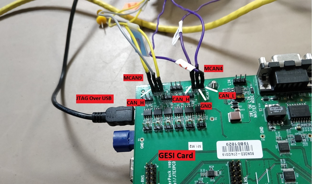
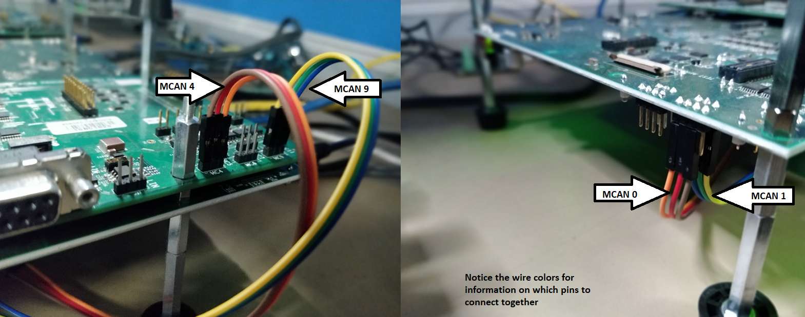
This demo uses MCAN4, MCAN9, and CPSW 9G's two ports (Port 2 and Port 3) on the GESI card. Conceptually, the wiring should be done as shown below:
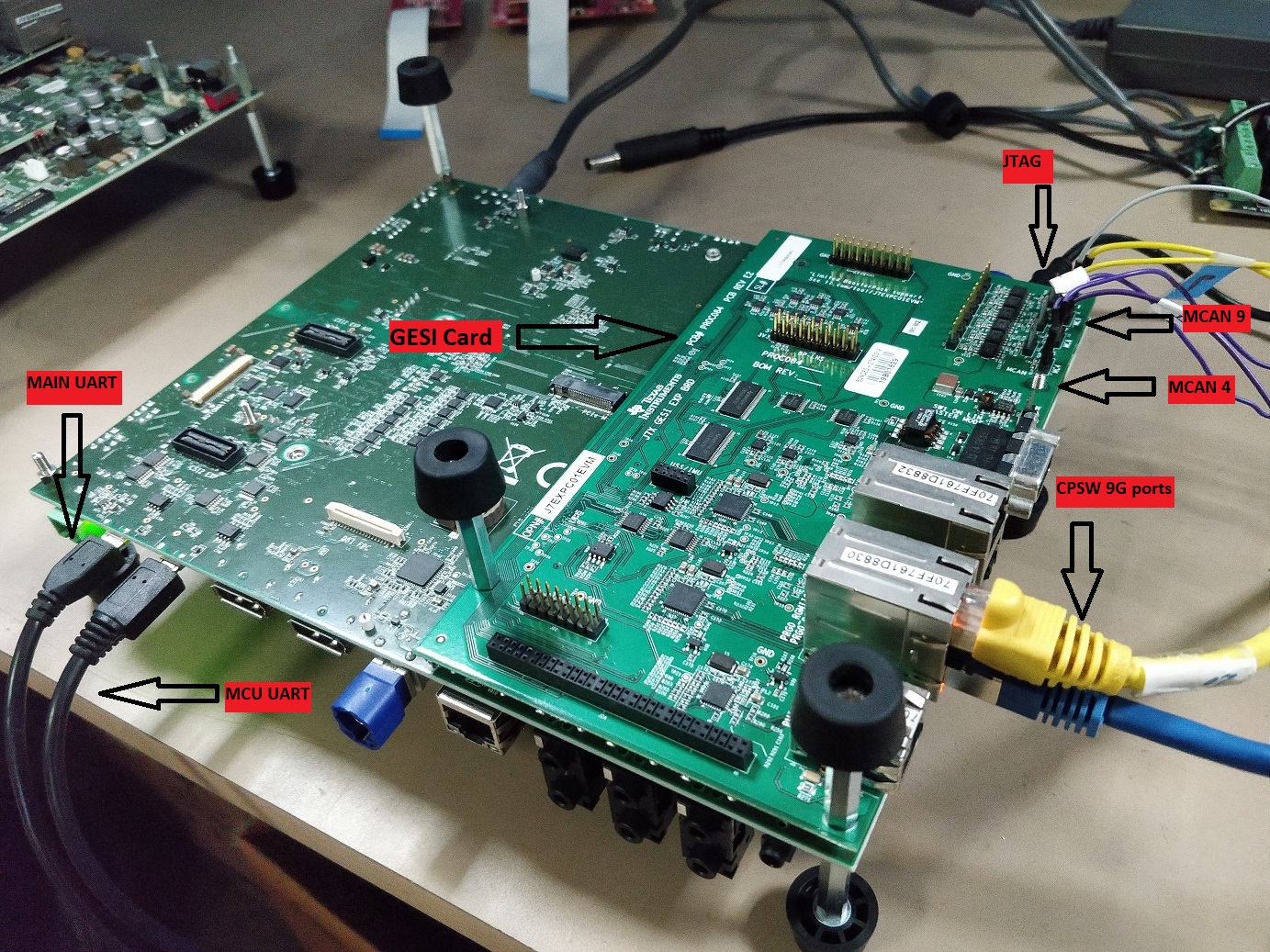
When actual connections are made it looks like below:
The connections for J7200 are identical except the CPSW 9G ports which use the SGMII ports on the add on QSGMII add-on card. Shown below:
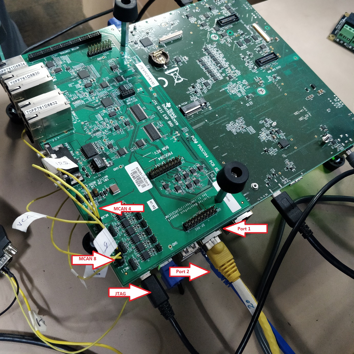
On J7200, the MCAN9 port is referred to as the MCAN8 port, but pins and wiring remains the same. The change is in the software.
As shown in the figure above, connect the two CPSW 9G Ethernet ports to PC's Ethernet ports and assign a fixed local IP to the interfaces to avoid unnecessary ARP traffic. If built-in NIC's are not available, then USB Ethernet NIC's can be used.
As shown in the picture below, connect the two USB-CAN analyzers to MCAN4 and MCAN8/9 instances, which are labeled as J30 and J32 respectively on the GESI card. The MCAN pin connection is as follows:
The following diagram shows the MCAN4 and MCAN9 connections on GESI card. MCAN8/9 has the same pin orientation (CAN_H, CAN_L and GND) as MCAN4.
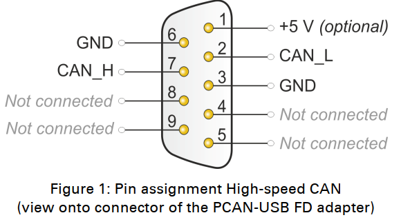
If using the PCAN tool, the DB-9 connection is as follows:
Routing inside the gateway demo is now configurable, users can configure it as per their requirements.
This is achieved through the use of a simple lookup table inside the gateway application with 256 entries. Each entry has two masks, one for Ethernet and one for CAN.
The masks tell which ports are open for Transmit. So if Eth mask is set to 0 then no packets are sent out of any Ethernet port, same for CAN.
See figure below on how this is done.
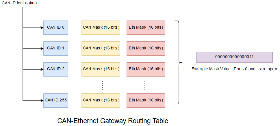
Using the CAN ID as an index allows for O(1) lookup time.
The framework has two parts
In addition to these two, there is a GUI based on open frameworks, which allows the user to visualize the CPU Load, latency, and throughput.
There are two raw socket based Ethernet tools, send_1722.out and recv_1722.out which are used for sending and receiving IEEE 1722 frames, respectively. Their usage is described below.
The tools can be built by the user by executing the make all command in the <SDK_INSTALL_PATH>/gateway-demos/can_eth_gateway/pctools directory. The tools provide multiple options to the user, and they can be accessed by running them with the --help option. So, for example, to understand the options provided with send_1722.out run the command:
sudo send_1722.out --help
Example usage:
sudo ./send_1722.out --eth_interface eth0 --gateway_mac 70:ff:76:1d:88:32 --dst_mac f8:b1:56:a6:86:e6 --ipg 1000 --route ETH --timeout 12
sudo ./recv_1722.out --eth_interface eth1 --timeout 12
sudo option is required since raw sockets in Linux require super user permission. As a result, even the python scripts that execute the automated tests require super user permission.
The analogous tool for CAN is called pcanfdtst, which supports both Tx and Rx modes. Its installation and usage is described below.
To install the PCAN Linux driver, follow these steps on your Linux PC. Ubuntu 18.04 is recommended.
Download the Peak CAN Linux driver ver. 8.9.3 from https://www.peak-system.com/fileadmin/media/linux/files/peak-linux-driver-8.9.3.tar.gz
Extract the package into your home directory or any other location.
Install the dependency of libpopt-dev package:
sudo apt-get install -y libpopt-dev
Run the following commands to build and install the driver:
  cd peak-linux-driver-8.9.3
  make all
  sudo make install
Finally, run the following command to enable the driver:
sudo modprobe pcan
If the command is successful and the PCAN-USB tool is plugged into PC, then the green light on the device will come up.
The default pcanfdtst tool provided in the Linux driver doesn't have the necessary extensions required for the automation. To do that, user needs to apply the patch specified here to the file pcanfdtst.c in the folder peak-linux-driver-8.9.3/test/src.
To patch and build the tool, copy the contents from the section PCAN Patch to a file, let's call it pcanfdtst.patch and then execute the following commands in the directory peak-linux-driver-8.9.3/test/src:
  patch pcanfdtst.c pcanfdtst.patch
  cd ..
  make all
This will build pcanfdtst tool in the peak-linux-driver-8.9.3/test directory.
The pcanfdtst tool has many options, to see all of them run the command:
./pcanfdtst --help
Example usage to receive packets at 1 Mbps bitrate and 5 Mbps data rate:
./pcanfdtst rx --bitrate 1000000 --dbitrate 5000000 --clock 80000000 --brs --fd -q -M 12 /dev/pcan32
There are four routes to test in the demo:
Each route requires running sender(s) and listener(s) tasks simultaneously. This is automatically done by the Python script called run_demo.py. Besides these four routes, the
script supports running System tests which enables all four routes simultaneously. The system tests can only be run with the GUI, which is described in Running GUI section.
Since the python script uses pcanfdtst utility from PCAN Linux Driver, the user first needs to copy the pctools folder to the folder peak-linux-driver-8.9.3/test:
cp -Rf <SDK_INSTALL_PATH>/gateway-demos/can_eth_gateway/pctools peak-linux-driver-8.9.3/test
User can now run the script from the peak-linux-driver-8.9.3/test folder. To find out what all option the script supports, run the command:
python3 pctools/run_demo.py --help
Due to hardcoded dependencies in the path of executables, the script must be run from the test folder as described above.
To run the demo, the Python script needs the following information:
CAN devices attached to the PC. The script needs to know which device is connected to MCAN4, and which one is connected to MCAN9. Users can see this by running the command:
lspcan
Ethernet devices attached to the PC (two are required). Users can see this by running the command:
ifconfig
MAC address of the Gateway application running on the Jacinto 7 EVM. This is either determined automatically or updated manually.
Providing so much information to the script is not easy, so the script provides a way to read this from a file. The file is called app_config.txt and should be kept
in the same folder as the script. A sample app_config.txt file is provided in <SDK_INSTALL_PATH>/gateway-demos/can_eth_gateway/pctools folder. If the Python script cannot find the file, then the script tries to generate it automatically with the help from the user. The interaction is self-explanatory, but an example is provided below with comments.
Example usage:
python3 pctools/run_demo.py --iterations 1 --run_time 5 --system_test 0 --gui_enabled 0
Here --iterations 1 tells the script to run the unit tests only once, --run_time 5 tells the script to run each iteration for 5 seconds and --gui_enabled 0 tells
the script not to invoke the GUI.
If the script cannot find app_config.txt, it will prompt the user with the following prompts:
Please remove any PCAN devices connected to the PC....hit Enter when ready
Now connect the first PCAN device to MCAN4 interface (J14) on the GESI card...refer to the setup diagram
At this point, if the user connects a PCAN-USB device to PC, then user will get the prompt:
Found one interface
Continuing with the prompts, the user gets:
Now connect the second PCAN device to MCAN9 interface (J6) on the GESI card...refer to the setup diagram
Please select the primary interface. Its usually the built in Ethernet card on a laptop or PC
Now, the user will be prompted with different ethernet interfaces on the PC and must select the appropriate interfaces connected to the Jacinto 7 EVM by entering Y or N. (See setup diagram)
For example, if eth0 and eth1 are connected to the Jacinto 7 EVM, then those must be selected:
Please select the secondary interface. Its usually a USB dongle on a laptop or a secondary NIC on a PC
At this prompt, user must select the second ethernet interface. Once that's done, the script will display something like:
--------Two CAN and two Ethernet Interfaces were added as shown below--------
CAN Interface for MCAN4 	: /dev/pcanusbfd32
CAN Interface for MCAN9 	: /dev/pcanusbfd33
Primary Eth Interface 		: enp1s2
Secondary Eth Interface 	: enxd037455f8444
If this is ok, then hit Y else hit N (to exit)
If the user proceeds and everything (Ethernet connection, CAN adapter, drivers, setup, cables) is OK, then user will get the prompt:
Found Gateway MAC. Good!
and the script will create the file app_config.txt file in the folder where the Python script is being run from. Else, the user will get the prompt:
Didn't get any packet from gateway, are you sure you are running it ? Maybe run wireshark and check ?
If this happens, then the user must debug the issue by checking each route manually and trying to figure out where the problem lies.
One can also attempt to create app_config.txt manually, if one is confident about the connections. Please see manually checking the routes section to debug the issue.
The routing table configuration is done automatically by the automation script. If you open run_demo.py file then you will see the following line.
sudo ./pctools/send_1722.out --eth_interface gateway_interfaces[3] --can_id gateway_interface_lut[gateway_interfaces[1]] --update_hash_table 1 --can_mask 0x1 --eth_mask 0x0
This line is used to configure the gateway for CAN 2 CAN routing such that CAN frames can only go out of the first port. No transmit from Ethernet ports is permitted.
The --can_id option is used to provide the CAN ID and --can_mask and --eth_mask are used to configure the Eth and CAN entries.
Below, one can see the sample output from a successful unit test run for all four routes:
Iteration # 0 : Script will now run individual tests

Script will now run CAN 2 CAN tests
-------------------CAN 2 CAN Test Results----------------------

Number of CAN frames sent 	:  7633
Number of CAN frames received 	:  7633
CAN interface received frames for 	:  5372364.000000 us

Script will now run CAN 2 Eth tests
-------------------CAN 2 ETH Test Results----------------------

Number of CAN frames sent 	:  7626
Number of Eth frames received 	:  7626

Eth interface received frames for 	:  6218675.000000 us

Script will now run Eth 2 Eth tests
-------------------ETH 2 ETH Test Results----------------------

Number of Eth frames sent 	:  5391
Number of Eth frames received 	:  5391

Eth interface received frames for 	:  6432795.000000 us

Script will now run Eth 2 CAN tests
-------------------ETH 2 CAN Test Results----------------------

Number of Eth frames sent 	:  16959
Number of CAN frames received on 1st interface 	:  16959

1st interface of CAN received packets for 	:  5022384.000000 us

Iteration # 0 completed
The command used to execute this test is:
python3 pctools/run_demo.py --iterations 1 --run_time 5 --system_test 0 --gui_enabled 0
As explained before, to run the unit tests, execute the command:
python3 pctools/run_demo.py --iterations 1 --run_time 5 --system_test 0 --gui_enabled 0
This will cycle through all the 4 routes, CAN-to-CAN, CAN-to-Eth, Eth-to-Eth and Eth-to-CAN cyclically once, while also displaying the statistics.
To run system tests, first run the GUI.
The GUI is packaged as a downloadable tarball in the Processor SDK Linux download page. The link is titled can-eth-gateway-demo-gui.tar.gz.
The GUI binaries have been compiled on an x86 machine running Ubuntu 18.04. If another Operating System or Ubuntu version is being used, then this will not work. At the moment, there is no plan to provide sources for compiling the GUI on a different Operating System.
The GUI has run-time dependencies on the Open Framework module, to install them follow the steps below.
./install_dependencies.sh as described on this pageTo run the GUI, extract the tarball in your machine at the location <GUI_INSTALL_DIR> and run the following commands to run the data aggregator:
cd <GUI_INSTALL_DIR>/aggregator/bin
./makefifo.sh
./ces-gui-data-aggregator
This will create the pipes and launch the aggregator, which serves as an Inter Process Communication system between the GUI and the PC tools.
Now, to run the actual GUI, run the following command in another terminal:
cd <GUI_INSTALL_DIR>/gui/bin
./ces2020-gui-template
This will launch a GUI which looks like this:
Now to see the GUI in action, run the following command in peak-linux-driver-8.9.3/test folder:
python3 pctools/run_demo.py --iterations 1 --run_time 20 --system_test 1 --gui_enabled 1
This will run the system tests for 20 seconds. If you see the GUI while the test is running, you will see the bars and dials moving.
This section describes how to manually check all four routes using the PCAN-USB FD tool or, for that matter, any other tool. Information provided here can also be used to debug the setup. We now describe how to test each route separately.
Do not use 0xAA as the first byte of any CAN message sent to CAN Eth Gateway as it's reserved for test automation
There are two CAN-to-CAN routes, MCAN4 to MCAN9 and vice versa. The routing is decided based on the value of some bytes in the CAN-FD message. These byte offsets have been chosen keeping future requirements in mind. If the user is using the customised tools provided with the demo, then this is handled automatically based on command line arguments. But if user has their own tools, then they need to re-create the message and use the particular Message ID.
The CAN ports on the Gateway (Jacinto 7 EVM) can only accept a particular extended message ID. This is documented below:
| CAN Port | Message ID |
|---|---|
| MCAN4 | 0xD0 |
| MCAN9 | 0xE0 |
If you see the sample app_config.txt file, then you will find the same information.
To send an extended CAN FD message from MCAN4 to MCAN9, run the following command in peak-linux-driver-8.9.3/test directory:
./pcanfdtst tx CAN_ONLY --bitrate 1000000 --dbitrate 5000000 --clock 80000000 -n 1 -ie 0xD0 --fd -l 64 --tx-pause-us 1000 /dev/pcanusbfd32
Here, we assume that /dev/pcanusbfd32 is connected to MCAN4.
This will send 1 CAN message with the ID 0xD0 with correct formatting to the gateway, which will route it to MCAN9.
To listen and display the CAN message being received on MCAN9, run the following command in another terminal:
./pcanfdtst rx --bitrate 1000000 --dbitrate 5000000 --clock 80000000 --fd -M 10 /dev/pcanusbfd33
If routing from MCAN9 to MCAN4, use the same message but change the message ID and CAN port. So the command will change to:
./pcanfdtst tx CAN_ONLY --bitrate 1000000 --dbitrate 5000000 --clock 80000000 -n 1 -ie 0xE0 --fd -l 64 --tx-pause-us 1000 /dev/pcanusbfd33
On the listener side, we will change the command to listen on a different port:
./pcanfdtst rx --bitrate 1000000 --dbitrate 5000000 --clock 80000000 --fd -M 10 /dev/pcanusbfd32
To do CAN-to-ETH routing, we need to configure the routing table appropriately as described in this section
To send on second Eth port, set the eth_mask field to 0x2. If sending on both Ethernet ports then eth_mask field should be 0x3.
While doing CAN to Eth routing, can_mask should be 0 or else there will be CAN 2 CAN routing.
To send packet from MCAN4 to both ETH ports, run this command:
./pcanfdtst tx ETH_ONLY --bitrate 1000000 --dbitrate 5000000 --clock 80000000 -n 1 -ie 0xD0 --fd -l 64 --tx-pause-us 1000 /dev/pcanusbfd32
On the listener side, we need to run this command in pctools directory to check for Ethernet frames:
sudo ./recv_1722.out --eth_interface eth0 --timeout 12 --pipes 0
Here, we assume that eth0 interface is connected to one of the GESI ethernet ports as shown in J7 Board setup.
To do Eth to Eth routing there are two requirements.
The ethernet packet to be sent must have the gateway MAC ID as it's destination MAC ID, this is a general requirement for sending any ethernet packet to the gateway.
The device must be aware of the MAC ID of the PC port on which it is to send a packet.
Both these requirements are taken care of by the send_1722.c tool, which reads the app_config.txt configuration file to know the PC and gateway device MAC addresses. The second requirement to tell the device about the MAC ID of the PC is also taken care of by the send_1722.c tool.
To configure the MAC address on the device, use the following command (also present in run_demo.py)
sudo ./pctools/send_1722.out --eth_interface ``70:ff:76:1d:88:32`` --send_mac_address 1
Additionally user must configure the routing table by setting the can_mask to 0 and eth_mask to appropriate value based on routing requirement.
To send packets, run the following command in the pctools directory:
sudo ./send_1722.out --eth_interface eth0 --gateway_mac 70:ff:76:1d:88:32 --dst_mac 00:ad:24:8f:f6:4e --ipg 1000 --route ETH --num_packets 10
This will send 10 packets on the interface eth0 to gateway device with a MAC ID of 70:ff:76:1d:88:32, where the MAC ID of other ethernet interface is 00:ad:24:8f:f6:4e.
Here, --ipg 1000 will add an approximate delay of 1000 us between two ethernet frames.
To receive packets, run the following command in the pctools directory:
sudo ./recv_1722.out --eth_interface eth1 --timeout 12 --pipes 0
To change routing from eth1 to eth0, swap the interface names and MAC ID in the sender and listener commands.
Here, we assume that eth0 and eth1 are ethernet interfaces connected to the GESI card.
To do Ethernet to CAN routing, we need to configure eth_mask and can_mask appropriately (see CAN to CAN section above) and run Ethernet sender and CAN receiver tasks.
Send 10 packets from eth0 to MCAN4 at an IPG of 1ms:
sudo ./send_1722.out --eth_interface eth0 --gateway_mac 70:ff:76:1d:88:32 --ipg 1000 --route MCAN4 --num_packets 10
Listen on MCAN4 for CAN messages for 10 seconds:
./pcanfdtst rx --bitrate 1000000 --dbitrate 5000000 --clock 80000000 --fd -M 10 /dev/pcanusbfd32
Here, we assume that /dev/pcanusbfd32 is connected to MCAN4.
The tool also supports sending output to both CAN ports. To do that, change the --route option to BOTH:
sudo ./send_1722.out --eth_interface eth0 --gateway_mac 70:ff:76:1d:88:32 --ipg 1000 --route BOTH --num_packets 10
For more details about installation of CCS and J721E/J7200 target creation, refer to the Processor SDK RTOS User's Guide inside "psdk_rtos/docs/user_guide" folder, which can be found in SDK installation.
Connect a micro USB cable to JTAG port of J721E/J7200 EVM. The XDS110 JTAG
connector is labeled XDS110 (J3).
Connect a micro USB cable to Main Domain UART port on J721E/J7200 EVM. Its
labeled Main UART (J44). This will create 4 UART ports from /dev/ttyUSB0 to /dev/ttyUSB3
Set EVM's DIP switches SW8 and SW9 for no-boot mode:
Power on the J721E/J7200 EVM board. Ensure that SD card is not present or QSPI flashed.
Open up a serial terminal to ttyUSB2 (third instance) for UART communication. This will show logs from MAIN_Cortex_R5F_0_1 core where the Ethernet remote switch runs.
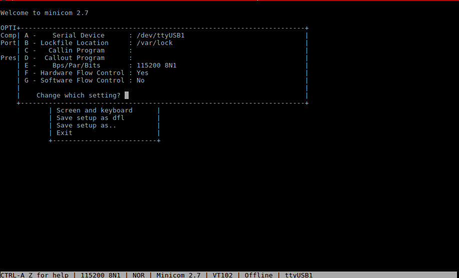
Set serial parameters to: 115200 8N1.
Set hardware and software flow control to "No".
Below figure shows serial parameters set in Minicom.
Open CCS and launch target config file for J721E/J7200 EVM.
Initialize the SoC and load system firmware using the launch.js script at <SDK_INSTALL_PATH>/pdk_j7200_07_03_00_29/packages/ti/drv/sciclient/tools/ccsLoadDmsc/j721e.
Wait for initialization and then connect to MCU_Cortex_R5_0. If there is already an application loaded then do a CPU Reset (Shift + Ctrl + R) and load and run the executable
<SDK_INSTALL_PATH>/gateway-demos/binary/can_traffic_generator_app/bin/j721e_evm/can_traffic_generator_app_mcu1_0_release.xer5f.
Now connect MAIN_Cortex_R5F_0_0 and load and run the demo executable:
<SDK_INSTALL_PATH>/ethfw/out/J721E/R5Ft/SYSBIOS/release/app_remoteswitchcfg_server.xer5f
Now connect to MAIN_Cortex_R5F_0_1 and load and run the demo executable:
<SDK_INSTALL_PATH>/gateway-demos/binary/can_eth_gateway_app/bin/j721e_evm/can_eth_gateway_app_mcu2_1_release.xer5f
The application should boot up with the CCS log shown below. Note that the Ethernet interface takes a few seconds to come up:
  Gateway App:Variant - Pre Compile being used !!!

  Gateway App: CDD IPC MCAL Version Info
  Gateway App:---------------------
  Gateway App: Vendor ID           : 44
  Gateway App: Starting CAN Rx
  Gateway App: Starting CAN Rx Interface
  Gateway App: Module ID           : 255
  Gateway App: SW Major Version    : 1
  Gateway App: SW Minor Version    : 3
  Gateway App: SW Patch Version    : 0

  DEM Error reported. EventId:65535  EventStatus:2
  DEM Error reported. EventId:65535  EventStatus:2
  Gateway App:MAC Port 1 Address: 70:ff:76:1d:88:32
  Gateway App: Starting Eth Rx Interface
  Gateway App: Starting Gateway Router
The 70:ff:76:1d:88:32 value shown above refers to the MAC address of the Gateway and is the same one that is used in ETH to ETH routing. It will change from device to device.
If UART is connected, then the user will see the following log from remote switch driver indicating a successful boot:
  =======================================================
      CPSW Ethernet Firmware
  =======================================================
  CPSW_5G Test on MAIN NAVSS
  EnetPhy_bindDriver: PHY 16: OUI:0001c1 Model:27 Ver:00 <-> 'vsc8514' : OK
  EnetPhy_bindDriver: PHY 17: OUI:0001c1 Model:27 Ver:00 <-> 'vsc8514' : OK
  EnetPhy_bindDriver: PHY 18: OUI:0001c1 Model:27 Ver:00 <-> 'vsc8514' : OK
  EnetPhy_bindDriver: PHY 19: OUI:0001c1 Model:27 Ver:00 <-> 'vsc8514' : OK
  PHY 0 is alive
  PHY 3 is alive
  PHY 16 is alive
  PHY 17 is alive
  PHY 18 is alive
  PHY 19 is alive
  PHY 23 is alive

  ETHFW Version   : 0.01.01
  ETHFW Build Date: Nov 12, 2020
  ETHFW Build Time: 23:38:03
  ETHFW Commit SHA: 44eae955

  Host MAC address: 70:ff:76:1d:88:31
  IPC_echo_test (core : mcu2_0) .....
  [NIMU_NDK] ENET has been started successfully
  Remote demo device (core : mcu2_0) .....
  CpswMacPort_checkSgmiiStatus: MAC 0: SGMII link parter config port: link up: 1-Gbps Full-Duplex
  Cpsw_handleLinkUp: Port 1: Link up: 1-Gbps Full-Duplex
  CpswMacPort_checkSgmiiStatus: MAC 1: SGMII link parter config port: link up: 1-Gbps Full-Duplex
  Cpsw_handleLinkUp: Port 2: Link up: 1-Gbps Full-Duplex
  Function:CpswProxyServer_attachExtHandlerCb,HostId:4,CpswType:5
  Function:CpswProxyServer_ioctlHandlerCb,HostId:4,Handle:a2bec00c,CoreKey:38acb976, Cmd:1010201,InArgsLen:24, OutArgsLen:4
  Function:CpswProxyServer_registerMacHandlerCb,HostId:4,Handle:a2bec00c,CoreKey:38acb976, MacAddress:70:ff:76:1d:88:32, FlowIdx:90, FlowIdxOffset:6
  Cpsw_ioctlInternal: CPSW: Registered MAC address.ALE entry:7, Policer Entry:0Function:CpswProxyServer_ioctlHandlerCb,HostId:4,Handle:a2bec00c,CoreKey:38acb976, Cmd:1010201,InArgsLen:24, OutArgsLen:4
OSPI boot is currently not functional for J721E, the alternative is to use CCS Boot. See (here)
OSPI boot mode is the fastest boot mode and the recommended option for evaluating gateway demo applications.
Download TI's uniflash tool from https://www.ti.com/tool/UNIFLASH (Ver. 6.1.0) and install in your Linux machine.
Connect a micro USB cable to MCU Domain UART port on J721E/J7200 EVM. Its labeled MCU UART (J43).
Open up a serial terminal to port ttyUSB1 for UART1 communication. This will be used to verify boot mode and flash OSPI binaries.
Set EVM's DIP switches SW8 and SW9 for UART boot mode:
Power cycle the EVM. You should see continuous CCCC prints on the console.
This means that the EVM is now in UART boot mode and ready to flash OSPI binaries.
Close the serial terminal or you won't be able to flash the binaries.
Build the binaries required for a successful OSPI boot.
Execute the following command in <SDK_INSTALL_PATH>/pdk_j7200_07_03_00_29/packages/ti/build:
make -s sbl_ospi_img
Run the script gen_combined_image.sh in <SDK_INSTALL_PATH>/gateway-demos/pctools to generate the image app_switch2.appimage
Please edit the script
gen_combined_image.shas per your requirement as the paths may not match sometimes
Now copy the following binaries and keep them in one folder, let's call it <OSPI_BINARIES>.
<SDK_INSTALL_PATH>/pdk_j7200_07_03_00_29/packages/ti/boot/sbl/binary/j721e_evm/ospi/bin/sbl_ospi_img_mcu1_0_release.tiimage to <OSPI_BINARIES> and rename it to tiboot3.bin.<SDK_INSTALL_PATH>/pdk_j7200_07_03_00_29/packages/ti/drv/sciclient/soc/V1/tifs.bin to <OSPI_BINARIES>.app_switch2.appimage to <OSPI_BINARIES>.pdk\packages\ti\board\src\flash\nor\ospi\nor_spi_patterns.bin to <OSPI_BINARIES>Navigate to the folder where Uniflash tool was installed and run the following command:
sudo ./dslite.sh --mode processors -c /dev/ttyUSB1 -f /<PATH_TO_UNIFLASH_TOOL>/uniflash_6.1.0/processors/FlashWriter/j721e_evm/uart_j721e_evm_flash_programmer_release.tiimage -i 0
If successful, then flash the following images, else power cycle the board and restart. Check for any open connections to the UART if trouble persists.
Run the following commands in succession:
 sudo ./dslite.sh --mode processors -c /dev/ttyUSB1 -f <OSPI_BINARIES>/tiboot3.bin -d 3 -o 0
 sudo ./dslite.sh --mode processors -c /dev/ttyUSB1 -f <OSPI_BINARIES>/sysfw.bin -d 3 -o 80000
 sudo ./dslite.sh --mode processors -c /dev/ttyUSB1 -f <OSPI_BINARIES>/app_switch2.appimage -d 3 -o 100000
 sudo ./dslite.sh --mode processors -c /dev/ttyUSB1 -f <OSPI_BINARIES>/nor_spi_patterns.bin -d 3 -o 3FC0000(J7200)/3FE0000(J721E)
On J721E, set EVM's DIP switches SW8 and SW9 for OSPI boot mode
On J7200, Set EVM's DIP switches SW8 and SW9 for xSPI boot mode
Connect a micro USB cable to Main Domain UART port on J721E_EVM. Its labeled Main UART (J44).
Open up a serial terminal to port ttyUSB4 for UART2 communication. This will be used to verify whether gateway application has booted correctly.
Power cycle the EVM. Gateway application should boot up, and you will see the log from Ethernet Firmware (see above).
The Out of Box demo is identical to the regular demo with the exception that no PCAN-USB devices are used. Hence it's much easier to setup.
To run the demo, the following connections need to be made
See the picture below on how connections are made with the help of two color coded jumper cable strips.
Out of Box demo does not support GUI or Manual checking of the routes
The low latency demo is a modified version of the can_traffic_generator_app and it's used to showcase that J7 family of devices are capable of routing traffic from one CAN port to another with extremely low latency.
See this section on how to build it.
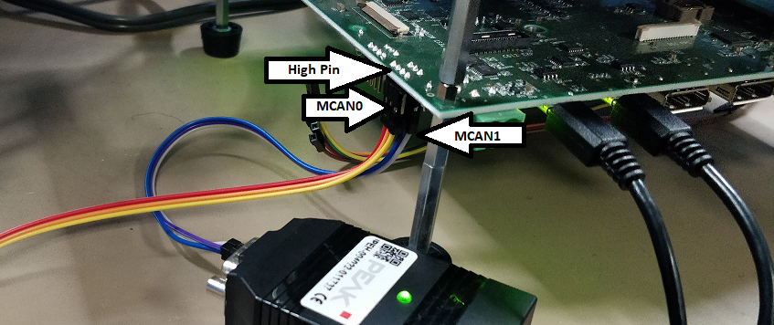
Running the demo is very simple. Connect a CAN device each to MCU MCAN0 and MCU MCAN1 ports.
Send a message with the extended CAN ID 0xD0 to MCU MCAN0 and it gets routed to MCU MCAN1 by default. The reverse is not true.
The latency is embedded in the 7th byte (counting from 1) of the payload in microsecond units.
If using the patched PCAN tool (see this), thn the average and maximum values are reported by the tool itself.
To send 10 CAN messages with the extended ID 0xD0 on say /dev/pcan32 which is connected to MCU MCAN0, use the following command:
./pcanfdtst tx --bitrate 1000000 --dbitrate 5000000 --clock 80000000 -ie 0xD0 --fd --brs -l 64 -w -n 10 /dev/pcan32
To receive a CAN messages on say /dev/pcan33 which is connected to MCU MCAN1, use this command :
./pcanfdtst NO_GUI rx --bitrate 1000000 --dbitrate 5000000 --clock 80000000 -q /dev/pcan33
When all packets have been sent, use Ctr-C to terminate the receiver application.
See picture below regarding connections. The MCU MCAN0 and MCU MCAN1 ports are the same ones which are used for OOB demo, except that they are connected to PCAN devices now.
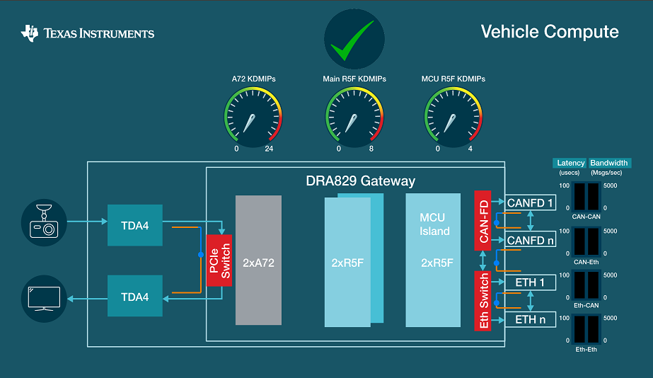
Three types of statistics are of concern to use when running gateway application.
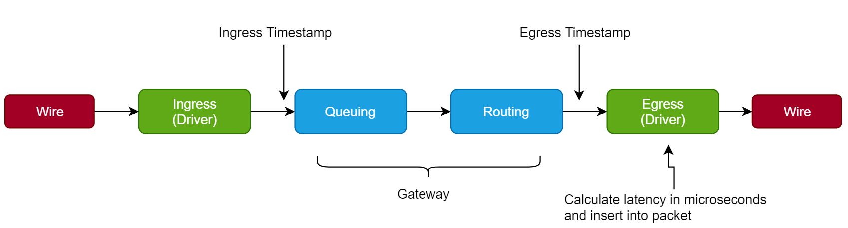
Bridge Delay or Latency : The time taken by Gateway to route a packet. This is measured internally by the gateway through timestamps, which is then inserted into the outgoing packet by the Gateway so it can be parsed by external tools. See figure below to understand more on how this is done.
Throughput : The number of packets sent/received in a given amount of time. This is calculated by external tools.
CPU Load : Gateway application measures it periodically in percentage terms and communicates this to recv_1722.out application. The tool, in turn, calculates an average and displays it along with other test results.
When a unit test is run, the test automation script automatically displays all the statistics from the test run.
index.html) at <SDK_INSTALL_PATH>/gateway-demosThe patch required for PCAN-USB tool is provided below. Use it without any modifications:
/* Copyright (C) {YEAR} Texas Instruments Incorporated - https://www.ti.com/
*  This program has been modified by Texas Instruments and those modifications are licensed as follows.
*
* This program is free software; you can redistribute it and/or
* modify it under the terms of the GNU General Public License as
* published by the Free Software Foundation version 2.
*
* This program is distributed "as is" WITHOUT ANY WARRANTY of any
* kind, whether express or implied; without even the implied warranty
* of MERCHANTABILITY or FITNESS FOR A PARTICULAR PURPOSE.  See the
* GNU General Public License for more details.
*/

--- pcanfdtst_orig.c	2019-10-29 16:12:45.000000000 +0530
+++ pcanfdtst.c	2020-01-22 18:06:37.318143383 +0530
@@ -126,6 +126,10 @@
/* number max of /dev/pcan interfaces tested at the same time */
#define TST_DEV_PCAN_MAX	8

+/*Scaling factors for GUI*/
+#define LATENCY_SCALING_FACTOR      500
+#define BW_SCALING_FACTOR   5000
+
enum tst_status { NOK, OK, END };
enum tst_seq_mode { FIXD, RAND, INCR };

@@ -231,6 +235,41 @@

static int exit_status = 0;

+#define CAN_ONLY        0xAA
+#define ETH_ONLY        0xBB
+#define ETH_AND_CAN     0xCC
+
+static int route = 0;
+/*Decides the route that CAN frames will take in gateway*/
+static int pipes_enabled = 1;
+/*Enable pipes in application. Enabled by default*/
+
+/*Variables to track CAN 2 CAN bridge delay*/
+static int min_can_2_can_bridge_delay = 0xffffffff;
+static int max_can_2_can_bridge_delay = 0;
+static int avg_can_2_can_bridge_delay = 0;
+
+/*Variables to track Eth 2 CAN bridge delay*/
+static int min_eth_2_can_bridge_delay = 0xffffffff;
+static int max_eth_2_can_bridge_delay = 0;
+static int avg_eth_2_can_bridge_delay = 0;
+
+/*Counters to calculate throughput*/
+static int can_2_can_counter = 0;
+struct timeval start_of_can_2_can;
+struct timeval end_of_can_2_can;
+
+static int eth_2_can_counter = 0;
+struct timeval start_of_eth_2_can;
+struct timeval end_of_eth_2_can;
+
+/*Named FIFO descriptors*/
+int fd_can_2_can_latency = 0;  //For CAN 2 CAN latency values
+int fd_can_2_can_bw = 0;       //For CAN 2 CAN Bandwidth
+
+int fd_eth_2_can_latency = 0;  //For Eth 2 CAN latency values
+int fd_eth_2_can_bw = 0;       //For Eth 2 CAN Bandwidth
+
#ifdef ONE_TASK_PER_DEVICE

/* if defined sem_wait() is used instead of sem_trywait() */
@@ -803,6 +842,7 @@
static int exit_application(int err)
{
    close_application();
+    double time_diff_usec = 0;

    if (pcan_device_opened > 0) {

@@ -816,6 +856,21 @@
            break;
        case TST_MODE_RX:
            lprintf(ALWAYS, "received frames: %u\n", tst_rx_count);
+            printf("Average CAN 2 CAN Delay : %d us\n", avg_can_2_can_bridge_delay);
+            printf("Max CAN 2 CAN Delay : %d us\n", max_can_2_can_bridge_delay);
+
+            printf("Average Eth 2 CAN Delay : %d us\n", avg_eth_2_can_bridge_delay);
+            printf("Max Eth 2 CAN Delay : %d us\n", max_eth_2_can_bridge_delay);
+
+            time_diff_usec = ((double)end_of_can_2_can.tv_sec * 1000000 + (double)end_of_can_2_can.tv_usec);
+            time_diff_usec -= ((double)start_of_can_2_can.tv_sec * 1000000 + (double)start_of_can_2_can.tv_usec);
+
+            printf("CAN 2 CAN test ran for : %f us \n", time_diff_usec);
+
+            time_diff_usec = ((double)end_of_eth_2_can.tv_sec * 1000000 + (double)end_of_eth_2_can.tv_usec);
+            time_diff_usec -= ((double)start_of_eth_2_can.tv_sec * 1000000 + (double)start_of_eth_2_can.tv_usec);
+
+            printf("ETH 2 CAN test ran for : %f us \n", time_diff_usec);
            break;
        default:
            break;
@@ -1720,6 +1775,13 @@
            lprintf(DEBUG,
                "CAN_Write(%p) returns %d\n", dev->handle, err);
#else
+            usleep(tst_tx_pause_us); //add delay as specified
+
+            //automation changes
+            if(route != 0)
+            {
+                pcan_msg->data[0] = route;
+            }
            err = pcanfd_send_msg(dev->fd, pcan_msg);
            lprintf(DEBUG, "pcanfd_send_msg(%d, "
                "msg id=%xh flags=%08xh len=%u) returns %d\n",
@@ -1931,7 +1993,19 @@
{
    struct pcanfd_msg *pcan_msg = dev->can_rx_msgs->list;
    enum tst_status tst_status = OK;
-	int m, err;
+	int m, err, bridge_delay;
+
+    double current_time_in_sec = 0;
+    int    num_packets_sent_in_window = 0;
+
+    static int    last_num_packets_count_can = 0;
+    static double last_updated_time_in_sec_can = 0;
+
+    static int    last_num_packets_count_eth = 0;
+    static double last_updated_time_in_sec_eth = 0;
+
+    //For writing to named pipe
+    char string_buf[20];

    /* be sure to multi read *ONLY* when in RX mode (in TX mode, a single
    * read MUST be used because this function is called when at least ONE
@@ -1941,14 +2015,12 @@
        dev->can_rx_msgs->count = dev->msgs_count;

        err = pcanfd_recv_msgs(dev->fd, dev->can_rx_msgs);
-
        lprintf(DEBUG, "pcanfd_recv_msgs(%d, %u) returns %d "
            "(msgs count=%u)\n",
            dev->fd, dev->msgs_count, err,
            dev->can_rx_msgs->count);
#else
        dev->can_rx_msgs->count = 0;
-
        err = pcanfd_recv_msgs_list(dev->fd,
                    dev->msgs_count,
                    dev->can_rx_msgs->list);
@@ -1971,8 +2043,110 @@
                dev->handle, err);
        pcanmsg_to_fd(pcan_msg, &msgv1);
#else
+        //Test automation changes
        err = pcanfd_recv_msg(dev->fd, pcan_msg);
-
+        if(pcan_msg->data_len != 0)
+        {
+            //Get the min, max and average bridge delay from payload
+            memcpy(&bridge_delay, &(pcan_msg->data[7]), 4);
+
+            /*Calculate for CAN 2 CAN*/
+            if(pcan_msg->data[6] == 0)
+            {
+                if(bridge_delay < min_can_2_can_bridge_delay) {
+                    min_can_2_can_bridge_delay = bridge_delay;
+                }
+
+                if(bridge_delay > max_can_2_can_bridge_delay) {
+                    max_can_2_can_bridge_delay = bridge_delay;
+                }
+
+                avg_can_2_can_bridge_delay = (8 * avg_can_2_can_bridge_delay + 2 * bridge_delay) / 10;
+
+                if(can_2_can_counter++ == 0)
+                {
+                    /*Get the start time*/
+                    gettimeofday (&start_of_can_2_can, NULL);
+                }
+
+                /*Get the end time*/
+                gettimeofday (&end_of_can_2_can, NULL);
+
+                current_time_in_sec = (double)end_of_can_2_can.tv_sec;
+                if((current_time_in_sec - last_updated_time_in_sec_can) >= 1)
+                {
+                    last_updated_time_in_sec_can = current_time_in_sec;
+                    /*1 second has elapsed. Get number of packets sent in this window*/
+                    num_packets_sent_in_window = can_2_can_counter - last_num_packets_count_can;
+                    last_num_packets_count_can = can_2_can_counter;
+
+                    /*Write CAN 2 CAN BW to pipe*/
+                    if(fd_can_2_can_bw)
+                    {
+                        float value = (float)num_packets_sent_in_window/(float)BW_SCALING_FACTOR;
+                        sprintf(string_buf, "%0.3f\n", value);
+                        write(fd_can_2_can_bw, string_buf, strlen(string_buf) + 1);
+                    }
+
+                }
+                //write latency to PIPE
+                if(fd_can_2_can_latency && ((can_2_can_counter % 200) == 0))
+                {
+                    float value = (float)avg_can_2_can_bridge_delay/(float)LATENCY_SCALING_FACTOR;
+                    sprintf(string_buf, "%0.3f\n", value);
+                    write(fd_can_2_can_latency, string_buf, strlen(string_buf) + 1);
+                }
+
+            }
+
+            /*Calculate for ETH 2 CAN*/
+            if(pcan_msg->data[6] == 1)
+            {
+                if(bridge_delay < min_eth_2_can_bridge_delay) {
+                    min_eth_2_can_bridge_delay = bridge_delay;
+                }
+
+                if(bridge_delay > max_eth_2_can_bridge_delay) {
+                    max_eth_2_can_bridge_delay = bridge_delay;
+                }
+
+                avg_eth_2_can_bridge_delay = (8 * avg_eth_2_can_bridge_delay + 2 * bridge_delay) / 10;
+
+                if(eth_2_can_counter++ == 0)
+                {
+                    /*Get the start time*/
+                    gettimeofday (&start_of_eth_2_can, NULL);
+                }
+
+                /*Get the end time*/
+                gettimeofday (&end_of_eth_2_can, NULL);
+                current_time_in_sec = (double)end_of_eth_2_can.tv_sec;
+                if((current_time_in_sec - last_updated_time_in_sec_eth) >= 1)
+                {
+                    last_updated_time_in_sec_eth = current_time_in_sec;
+                    /*1 second has elapsed. Get number of packets sent in this window*/
+                    num_packets_sent_in_window = eth_2_can_counter - last_num_packets_count_eth;
+                    last_num_packets_count_eth = eth_2_can_counter;
+
+                    /*Write ETH 2 CAN BW to pipe*/
+                    if(fd_eth_2_can_bw)
+                    {
+                        float value = (float)num_packets_sent_in_window/(float)BW_SCALING_FACTOR;
+                        sprintf(string_buf, "%0.3f\n", value);
+                        write(fd_eth_2_can_bw, string_buf, strlen(string_buf) + 1);
+                    }
+                }
+
+                //write latency to PIPE
+                if(fd_eth_2_can_latency && ((eth_2_can_counter % 200) == 0))
+                {
+                    float value = (float)avg_eth_2_can_bridge_delay/(float)LATENCY_SCALING_FACTOR;
+                    sprintf(string_buf, "%0.3f\n", value);
+                    write(fd_eth_2_can_latency, string_buf, strlen(string_buf) + 1);
+                }
+            }
+
+        }
        lprintf(DEBUG, "pcanfd_recv_msg(%d) returns %d\n",
                dev->fd, err);
#endif
@@ -2189,9 +2363,9 @@
    if (tst_mode == TST_MODE_TX)
        tst = handle_tx_tst(pdev);

-	if (pdev->pause_us)
-		if (usleep(pdev->pause_us))
-			tst = handle_errno(errno, pdev);
+	//if (pdev->pause_us)
+	//	if (usleep(pdev->pause_us))
+	//		tst = handle_errno(errno, pdev);

    return tst;
}
@@ -2997,7 +3171,15 @@
            tst_mode = TST_MODE_REC;
        } else if (!strncmp(argv[i], "none", 4)) {
            tst_mode = TST_MODE_NONE;
-		} else if (pcan_device_count < TST_DEV_PCAN_MAX) {
+        } else if (!strcmp(argv[i], "CAN_ONLY")) {
+            route = CAN_ONLY;
+        } else if (!strcmp(argv[i], "ETH_ONLY")) {
+            route = ETH_ONLY;
+		} else if (!strcmp(argv[i], "ETH_AND_CAN")) {
+            route = ETH_AND_CAN;
+        } else if (!strcmp(argv[i], "NO_GUI")) {
+            pipes_enabled = 0;  /*Disable pipes if no GUI*/
+        } else if (pcan_device_count < TST_DEV_PCAN_MAX) {
            memset(pdev, '\0', sizeof(*pdev));

            pdev->name = argv[i];
@@ -3070,7 +3252,55 @@
#endif
#endif /* RT */

-	run_application();
+    //GUI automation code
+    //Open pipes to send data
+
+    if(tst_mode == TST_MODE_RX && pipes_enabled)
+    {
+        if((fd_can_2_can_latency = open("/tmp/can-latency-pipe", O_WRONLY)) < 0)
+        {
+            printf("Could not open can 2 can latency FIFO \n");
+        }
+
+        if((fd_can_2_can_bw = open("/tmp/can-bw-pipe", O_WRONLY)) < 0)
+        {
+            printf("Could not open can 2 can BW FIFO \n");
+        }
+
+        if((fd_eth_2_can_latency = open("/tmp/e2c-latency-pipe", O_WRONLY)) < 0)
+        {
+            printf("Could not open eth 2 can latency FIFO \n");
+        }
+
+        if((fd_eth_2_can_bw = open("/tmp/e2c-bw-pipe", O_WRONLY)) < 0)
+        {
+            printf("Could not open eth 2 can BW FIFO \n");
+        }
+    }
+
+    run_application();
+
+    //Close the named pipes
+
+    if(fd_can_2_can_latency)
+    {
+        close(fd_can_2_can_latency);
+    }
+
+    if(fd_can_2_can_bw)
+    {
+        close(fd_can_2_can_bw);
+    }
+
+    if(fd_eth_2_can_latency)
+    {
+        close(fd_eth_2_can_latency);
+    }
+
+    if(fd_eth_2_can_bw)
+    {
+        close(fd_eth_2_can_bw);
+    }

    return exit_application(exit_status);
}