3.2.2.10. CPSW2g Ethernet
- Introduction
- Driver Configuration
- Device tree bindings
- MAC mode
- Errata: i2329 MDIO interface corruption (CPSW and PRUSS)
3.2.2.10.1. Introduction
The TI J721E SoC Gigabit Ethernet Switch subsystem (CPSW NUSS) has two ports and provides Ethernet packet communication for the device. It supports MII interfaces the Reduced Gigabit Media Independent Interface (RGMII), Reduced Media Independent Interface (RMII), and the Management Data Input/Output (MDIO) interface for physical layer device (PHY) management.
The TI J721E SoC has integrated two-port Gigabit Ethernet Switch subsystem into device MCU domain named MCU_CPSW0 and has only one external Ethernet port (port 1) with selectable RGMII and RMII interfaces and an internal Communications Port Programming Interface (CPPI) port (Host port 0). Host Port 0 CPPI Packet Streaming Interface interface supports 8 TX channels and one RX channel operating by TI J721E NAVSS Unified DMA Peripheral Root Complex (UDMA-P) controller.
The driver follows the standard Linux network interface architecture and supports the following features:
- 10/100/1000 Mbps mode of operation.
- Auto negotiation.
- Linux NAPI support
- VLAN filtering
- Ethertool
- CPTS/PTP as per 802.1AS-2011 (TSN)
- EST/TAS offload as per 802.1Q-2018 (TSN)
- IET/preemption offload as per 802.1Q-2018 (TSN)
- Forwarding and Queuing Enhancements for Time-Sensitive Streams (FQTSS) as per 802.1Q-2018 previously referred to as CBS or 802.1Qav
Not supported:
- Interrupt Pacing is not supported by HW. NAPI is used by driver.
3.2.2.10.2. Driver Configuration
The TI Processor SDK has J721E MCU CPSW2g driver enabled by default. In case of custom builds, please ensure following configs are enabled.
CONFIG_TI_DAVINCI_MDIO
CONFIG_TI_CPSW_ALE
CONFIG_TI_AM65_CPSW_NUSS
CONFIG_TI_AM65_CPTS
CONFIG_TI_AM65_CPSW_TAS
CONFIG_PHY_TI_GMII_SEL
Module Build
Module build for the cpsw driver is supported. To do this, use option ‘m’ for above configs, where applicable.
3.2.2.10.3. Device tree bindings
The DT bindings description can be found at:
3.2.2.10.4. MAC mode
Bringing Up interface
The network interface can be configured automatically depending on root file system or configured manually. Manual configuration:
ip addr add 192.168.1.1/24 dev eth0
ip link set dev eth0 up

< or >

ifconfig eth0 <ip> netmask <mask> up
Get driver information
The MCU_CPSW0 interface can be identified by using ethtool -i|--driver command.
It also provides some information about supported features.
# ethtool -i <dev>
driver: am65-cpsw-nuss
version: 0.1
firmware-version:
expansion-rom-version:
bus-info: 46000000.ethernet
supports-statistics: yes
supports-test: no
supports-eeprom-access: no
supports-register-dump: yes
supports-priv-flags: yes
ethtool - Display standard information about device/link
   # ethtool eth0
Supported ports: [ TP MII ]
Supported link modes:   10baseT/Half 10baseT/Full
                        100baseT/Half 100baseT/Full
                        1000baseT/Half 1000baseT/Full
Supported pause frame use: Symmetric Receive-only
Supports auto-negotiation: Yes
Supported FEC modes: Not reported
Advertised link modes:  10baseT/Half 10baseT/Full
                        100baseT/Half 100baseT/Full
                        1000baseT/Half 1000baseT/Full
Advertised pause frame use: No
Advertised auto-negotiation: Yes
Advertised FEC modes: Not reported
Link partner advertised link modes:  10baseT/Half 10baseT/Full
                                     100baseT/Half 100baseT/Full
Link partner advertised pause frame use: Symmetric
Link partner advertised auto-negotiation: Yes
Link partner advertised FEC modes: Not reported
Speed: 100Mb/s
Duplex: Full
Port: MII
PHYAD: 0
Transceiver: internal
Auto-negotiation: on
Supports Wake-on: d
Wake-on: d
Current message level: 0x00000000 (0)

Link detected: yes
RX checksum offload
The Driver enables RX checksum offload by default. It can be disabled/enabled by using ethtool -K command:
# ethtool -k <dev>
....
rx-checksumming: on
ethtool -K <dev> rx-checksum on|off
VLAN Config
VLAN can be added/deleted using ip or vconfig utility.
VLAN Add
ip link add link eth0 name eth0.5 type vlan id 5

< or >

vconfig add eth0 5
VLAN del
ip link del eth0.5

< or >

vconfig rem eth0 5
VLAN IP assigning
IP address can be assigned to the VLAN interface either via udhcpc
when a VLAN aware dhcp server is present or via static ip assigning
using ip or ifconfig.
Once VLAN is added, it will create a new entry in Ethernet interfaces like eth0.5, below is an example how it check the vlan interface
ip addr add 192.168.1.1/24 dev eth0.5

< or >

ifconfig eth0.5
....
eth0.5    Link encap:Ethernet  HWaddr 20:CD:39:2B:C7:BE
          inet addr:192.168.10.5  Bcast:192.168.10.255  Mask:255.255.255.0
          UP BROADCAST RUNNING MULTICAST  MTU:1500  Metric:1
          RX packets:0 errors:0 dropped:0 overruns:0 frame:0
          TX packets:0 errors:0 dropped:0 overruns:0 carrier:0
          collisions:0 txqueuelen:0
          RX bytes:0 (0.0 B)  TX bytes:0 (0.0 B)
VLAN Packet Send/Receive
To Send or receive packets with the VLAN tag, bind the socket to the proper Ethernet interface shown above and can send/receive via that socket-fd.
Multicast Add/Delete
Multicast MAC address can be added/deleted using ip maddr commands or Linux socket ioctl SIOCADDMULTI/SIOCDELMULTI.
Show muliticast address
# ip maddr show dev <dev>
2:      eth0
    link  01:00:5e:00:00:01
    link  01:80:c2:00:00:00
    link  01:80:c2:00:00:03
    link  01:80:c2:00:00:0e
    link  01:00:5e:00:00:fc
    inet  224.0.0.252
    inet  224.0.0.1
Add muliticast address
# ip maddr add 01:00:5e:00:00:05 dev eth0
# ip maddr show dev eth0
2:      eth0
    link  01:00:5e:00:00:01
    link  01:80:c2:00:00:00
    link  01:80:c2:00:00:03
    link  01:80:c2:00:00:0e
    link  01:00:5e:00:00:fc
    link  01:00:5e:00:00:05 static
    inet  224.0.0.252
    inet  224.0.0.1
Delete muliticast address
# ip maddr del 01:00:5e:00:00:05 dev eth0
ethtool -P|--show-permaddr DEVNAME Show permanent hardware
address
# ethtool -P eth0
Permanent address: a0:f6:fd:a6:46:6e"
ethtool -s|--change DEVNAME Change generic options
Below commands will be redirected to the phy driver:
# ethtool -s <dev>
[ speed %d ]
[ duplex half|full ]
[ autoneg on|off ]
[ wol p|u|m|b|a|g|s|d... ]
[ sopass %x:%x:%x:%x:%x:%x ]
Note
CPSW driver do not perform any kind of WOL specific actions or configurations.
#ethtool -s eth0 duplex half speed 100
[ 3550.892112] cpsw 48484000.ethernet eth0: Link is Down
[ 3556.088704] cpsw 48484000.ethernet eth0: Link is Up - 100Mbps/Half - flow control off
Sets the driver message type flags by name or number
[ msglvl %d | msglvl type on|off ... ]
# ethtool -s eth0 msglvl drv off
# ethtool -s eth0 msglvl ifdown off
# ethtool -s eth0 msglvl ifup off
# ethtool eth0
Current message level: 0x00000031 (49)
                       drv ifdown ifup
ethtool -r|--negotiate DEVNAME Restart N-WAY negotiation
# ethtool -r eth0
[ 4338.167685] cpsw 48484000.ethernet eth0: Link is Down
[ 4341.288695] cpsw 48484000.ethernet eth0: Link is Up - 1Gbps/Full - flow control rx/tx"
ethtool -a|--show-pause DEVNAME Show pause options
# ethtool -a eth0
Pause parameters for eth0:
Autonegotiate:  off
RX:             off
TX:             off
ethtool -A|--pause DEVNAME Set pause options
# ethtool -A eth0 rx on tx on
cpsw 48484000.ethernet eth0: Link is Up - 1Gbps/Full - flow control rx/tx
# ethtool -a eth0
Pause parameters for eth0:
Autonegotiate:  off
RX:             on
TX:             on
ethtool -g|--show-ring DEVNAME Query RX/TX ring parameters
# ethtool -g eth0
Ring parameters for eth0:
Pre-set maximums:
RX:             0
RX Mini:        0
RX Jumbo:       0
TX:             0
Current hardware settings:
RX:             500
RX Mini:        0
RX Jumbo:       0
TX:             512
ethtool-l|--show-channels DEVNAME Query Channels
# ethtool -l eth0
Channel parameters for eth0:
Pre-set maximums:
RX:             1
TX:             8
Other:          0
Combined:       0
Current hardware settings:
RX:             1
TX:             8
Other:          0
Combined:       0
ethtool -L\|--set-channels DEVNAME Set Channels.
Allows to control number of TX channels driver is allowed to work with at DMA level. The maximum number of TX channels is 8.
Supported options [ tx N ]:
# ethtool -L eth0 tx 3
ethtool --show-priv-flags/--set-priv-flags DEVNAME Show/Set private flags
Allows to control private flags supported by driver.
| Flag | |
|---|---|
| p0-rx-ptype-rrobin | Controls TX DMA channels processing mode: round-robin or priority mode. In case priority mode is enabled, the high number channel will have higher priority: TX 7 - prio 7 … TX 0 - prio 0. |
| iet-frame-preemption | Enables support for Interspersed Express Traffic (IET) IEEE 802.3br (frame preemption). |
| iet-mac-verify | Enables Interspersed Express Traffic (IET) MAC verification procedure on link up event. |
# ethtool --show-priv-flags eth0
Private flags for eth0:
p0-rx-ptype-rrobin  : on
iet-frame-preemption: off
iet-mac-verify      : off

# ethtool --set-priv-flags eth0 p0-rx-ptype-rrobin off
Note
The network interface have to be down for private flags configuration.
ethtool -S|--statistics DEVNAME Show adapter statistics
“ethtool -S” command displays statistic for both external Port 1 and Host port 0. Host port 0 statistics prefixed with p0_.
 # ethtool -S eth0
NIC statistics:
     p0_rx_good_frames: 347
     p0_rx_broadcast_frames: 4
     p0_rx_multicast_frames: 264
     p0_rx_crc_errors: 0
     p0_rx_oversized_frames: 0
     p0_rx_undersized_frames: 0
     p0_ale_drop: 0
     p0_ale_overrun_drop: 0
     p0_rx_octets: 25756
     p0_tx_good_frames: 4816
     p0_tx_broadcast_frames: 3629
     p0_tx_multicast_frames: 1120
     p0_tx_octets: 878055
     p0_tx_64B_frames: 735
     p0_tx_65_to_127B_frames: 1023
     ...
     rx_good_frames: 4816
     rx_broadcast_frames: 3629
     rx_multicast_frames: 1120
     rx_pause_frames: 0
     rx_crc_errors: 0
     rx_align_code_errors: 0
     rx_oversized_frames: 0
     rx_jabber_frames: 0
     rx_undersized_frames: 0
     rx_fragments: 0
     ale_drop: 0
     ale_overrun_drop: 0
     rx_octets: 878055
     tx_good_frames: 347
     tx_broadcast_frames: 4
     tx_multicast_frames: 264
     tx_pause_frames: 0
     tx_deferred_frames: 0
     tx_collision_frames: 0
     tx_single_coll_frames: 0
     tx_mult_coll_frames: 0
     tx_excessive_collisions: 0
     tx_late_collisions: 0
     ...
ethtool -T|--show-time-stamping DEVNAME Show time stamping
capabilities.
Accessible when CPTS is enabled.
  # ethtool -T eth0
Time stamping parameters for eth0:
Capabilities:
        hardware-transmit     (SOF_TIMESTAMPING_TX_HARDWARE)
        software-transmit     (SOF_TIMESTAMPING_TX_SOFTWARE)
        hardware-receive      (SOF_TIMESTAMPING_RX_HARDWARE)
        software-receive      (SOF_TIMESTAMPING_RX_SOFTWARE)
        software-system-clock (SOF_TIMESTAMPING_SOFTWARE)
        hardware-raw-clock    (SOF_TIMESTAMPING_RAW_HARDWARE)
PTP Hardware Clock: 1
Hardware Transmit Timestamp Modes:
        off                   (HWTSTAMP_TX_OFF)
        on                    (HWTSTAMP_TX_ON)
Hardware Receive Filter Modes:
        none                  (HWTSTAMP_FILTER_NONE)
        all                   (HWTSTAMP_FILTER_ALL)
ethtool --show-eee DEVNAME Show EEE settings
#ethtool --show-eee eth0
EEE Settings for eth0:
        EEE status: not supported
ethtool --set-eee DEVNAME Set EEE settings.
Note
Full EEE is not supported in driver, but it enables reading and writing of EEE advertising settings in Ethernet PHY. This way one can disable advertising EEE for certain speeds.
ethtool -d|--register-dump DEVNAME Do a register dump
This command dumps all CPSW MMIO regions in the below format. The TI switch-config tool can be used for CPSW NUSS register dump parsing.
| MMIO region header (8 Bytes) | |
|---|---|
| module_id (u32) | MMIO region id NUSS = 1, RGMII_STATUS = 2, MDIO = 3, CPSW = 4, CPSW_P0 = 5, CPSW_P1 = 6, CPSW_CPTS = 7, CPSW_ALE = 8, CPSW_ALE_TBL = 9 |
| len (u32) | MMIO region dump length, including header |
| MMIO region registers dump (num_regs * 8 Bytes) | |
| reg_offset (u32) | register offset from the start of MCU NAVSS MMIO space |
| reg_value (u32) | MMIO region dump length, including header |
Exception: ALE table dumped as raw array of ALE records (3 * u32 per record).
# ethtool -d eth0
Offset          Values
------          ------
0x0000:         01 00 00 00 48 00 00 00 00 00 00 00 00 71 a0 6b
0x0010:         04 00 00 00 00 00 00 00 08 00 00 00 00 00 00 00
0x0020:         0c 00 00 00 00 00 00 00 10 00 00 00 01 00 00 00
0x0030:         14 00 00 00 00 00 00 00 18 00 00 00 00 00 00 00
0x0040:         1c 00 00 00 00 00 00 00 02 00 00 00 48 00 00 00
0x0050:         30 00 00 00 0b 00 00 00 34 00 00 00 00 00 00 00
0x0060:         38 00 00 00 00 00 00 00 3c 00 00 00 00 00 00 00
...
3.2.2.10.4.1. Interrupt pacing
The Interrupt pacing (IRQ coalescing) based on hrtimers for RX/TX data path separately can be enabled by following ethtool commands (min value is 20us).
The RX data path - only one queue:
# ethtool -C ethX rx-usecs N
The TX data path - any of enabed TX queue (up to 8):
- by default enables coalesing for TX0
  # ethtool -C ethX tx-usecs N

- configure TX0
  # ethtool -Q ethX queue_mask 1 --coalesce tx-usecs N

- configure TX1
  # ethtool -Q ethX queue_mask 2 --coalesce tx-usecs N

- configure TX0 and TX1
  # ethtool -Q ethX queue_mask 3 --coalesce tx-usecs N --coalesce tx-usecs N
The Interrupt pacing (IRQ coalescing) configuration can be retrieved by commands:
  # ethtool -c ethX

- show configuration for TX0 and TX1:
  # ethtool -Q eth0 queue_mask 3 --show-coalesce
It is also possible to use standard Linux Net core hard irqs deferral feature which can be enabled by configuring:
/sys/class/net/ethX/
 gro_flush_timeout (in ns)
 napi_defer_hard_irqs (number of retries)
Enabling of hard IRQ will be deferred napi_defer_hard_irqs times with gro_flush_timeout timeout.
The main difference of the hard irqs deferral feature from ethtool interrupt pacing (IRQ coalescing) is that it affects on both RX/TX data path and all TX/RX queues simultaneously.
3.2.2.10.4.2. Common Platform Time Sync (CPTS) module
The Common Platform Time Sync (CPTS) module is used to facilitate host control of time sync operations. It enables compliance with the IEEE 1588-2008 standard for a precision clock synchronization protocol.
The support for CPTS module can be enabled by Kconfig option CONFIG_TI_AM65_CPTS or through menuconfig tool. The PTP packet timestamping can be enabled only for one CPSW port.
When CPTS module is enabled it will exports a kernel interface for specific clock drivers and a PTP clock API user space interface and enable support for SIOCSHWTSTAMP and SIOCGHWTSTAMP socket ioctls. The PTP exposes the PHC as a character device with standardized ioctls which usually can be found at path:
/dev/ptpN
Supported PTP hardware clock functionality:
Basic clock operations
   - Set time
   - Get time
   - Shift the clock by a given offset atomically
   - Adjust clock frequency
Ancillary clock features
   - Time stamp external events
   - Periodic output signals configurable from user space
   - Synchronization of the Linux system time via the PPS subsystem
Supported parameters for SIOCSHWTSTAMP and SIOCGHWTSTAMP:
SIOCSHWTSTAMP
   hwtstamp_config.flags = 0
   hwtstamp_config.tx_type
       HWTSTAMP_TX_ON - enables hardware time stamping for outgoing packets
       HWTSTAMP_TX_OFF - no outgoing packet will need hardware time stamping
   hwtstamp_config.rx_filter
       HWTSTAMP_FILTER_NONE - time stamp no incoming packet at all
       HWTSTAMP_FILTER_ALL - time stamp any incoming packet
CPTS PTP packet timestamping default configuration when enabled (SIOCSHWTSTAMP):
CPSW_PN_TS_CTL_REG
   TS_MSG_TYPE_EN = 0xF (Sync, Delay_Req, Pdelay_Req, and Pdelay_Resp.)
   TS_TX_ANNEX_F_EN = 1
   TS_TX_ANNEX_E_EN = 1
   TS_TX_ANNEX_D_EN = 1
   TS_TX_VLAN_LTYPE1_E = 1
CPSW_PN_TS_CTL_LTYPE2_REG
   TS_TTL_NONZERO = 1
   TS_320 = 1
   TS_319 = 1
   TS_132 = 1
   TS_131 = 1
   TS_130 = 1
   TS_129 = 1
   TS_107 = 1
   TS_LTYPE1 = 0x88F7 (ETH_P_1588)
CPSW_PN_TS_SEQ_LTYPE_REG
   TS_SEQ_ID_OFFSET = 0x1e
   TS_LTYPE1 = 0x88F7 (ETH_P_1588)
CPSW_PN_TS_VLAN_LTYPE_REG
   TS_VLAN_LTYPE1 =  0x8100 (ETH_P_8021Q)
For more information about PTP clock API and Network timestamping see Linux kernel documentation
For additional information regarding TSN testing, refer TSN with CPSW
Testing using ptp4l tool from linuxptp project
To check the ptp clock adjustment with PTP protocol, a PTP slave (client) and a PTP master (server) applications are needed to run on separate devices (EVM or PC). Open source application package linuxptp can be used as slave and as well as master. Hence TX timestamp generation can be delayed (especially with low speed links) the ptp4l “tx_timestamp_timeout” parameter need to be set for ptp4l to work.
- create file ptp.cfg with content as below:
[global]
tx_timestamp_timeout     400
- pass configuration file to ptp4l using “-f” option:
ptp4l -E -2 -H -i eth0 -l 6 -m -q -p /dev/ptpN -f ptp.cfg
- Slave Side Examples
The following command can be used to run a ptp-over-L4 client on the evm in slave mode
./ptp4l -E -4 -H -i eth0 -s -l 7 -m -q -p /dev/ptpN
For ptp-over-L2 client, use the command
./ptp4l -E -2 -H -i eth0 -s -l 7 -m -q -p /dev/ptpN
- Master Side Examples
ptp4l can also be run in master mode. For example, the following command starts a ptp4l-over-L2 master on an EVM using hardware timestamping,
./ptp4l -E -2 -H -i eth0 -l 7 -m -q -p /dev/ptpN
On a Linux PC which does not support hardware timestamping, the following command starts a ptp4l-over-L2 master using software timestamping.
./ptp4l -E -2 -S -i eth0 -l 7 -m -q
Testing using testptp tool from Linux kernel
- get the ptp clock time
# testptp -d /dev/ptpN -g
clock time: 1493255613.608918429 or Thu Apr 27 01:13:33 2017
- query the ptp clock’s capabilities
# testptp -d /dev/ptpN -c
capabilities:
  10000000 maximum frequency adjustment (ppb)
  0 programmable alarms
  4 external time stamp channels
  2 programmable periodic signals
  1 pulse per second
  0 programmable pins
  0 cross timestamping
- Sanity testing of cpts ref frequency
Time difference between to testptp -g calls should be equal sleep time
# testptp -g -d /dev/ptpN && sleep 5 && testptp -g -d /dev/ptpN
clock time: 1493255884.565859901 or Thu Apr 27 01:18:04 2017
clock time: 1493255889.611065421 or Thu Apr 27 01:18:09 2017
- shift the ptp clock time by ‘val’ seconds
# testptp -g -d /dev/ptpN && testptp -t 100 && testptp -g -d /dev/ptpN
clock time: 1493256107.640649117 or Thu Apr 27 01:21:47 2017
time shift okay
clock time: 1493256207.678819093 or Thu Apr 27 01:23:27 2017
- set the ptp clock time to ‘val’ seconds
# testptp -g -d /dev/ptpN && testptp -T 1000000 && testptp -g -d /dev/ptpN
clock time: 1493256277.568238925 or Thu Apr 27 01:24:37 2017
set time okay
clock time: 100.018944504 or Thu Jan  1 00:01:40 1970
- adjust the ptp clock frequency by ‘val’ ppb
# testptp -g -d /dev/ptpN && testptp -f 1000000 && testptp -g -d /dev/ptpN
clock time: 151.347795184 or Thu Jan  1 00:02:31 1970
frequency adjustment okay
clock time: 151.386187454 or Thu Jan  1 00:02:31 1970
Example of using Time stamp external events
Timestamping of external events can be tested using testptp tool. Before testing the proper CPTS signal routing has to be done by using timesync router in DT.
For example, output of GENF0 can be routed to HW3_TS_PUSH_EN input. It’s required to rebuild kernel with below changes first
#define TS_OFFSET(pa, val) (0x4+(pa)*4) (0x80000000 | val)
×ync_router {
pinctrl-names = "default";
pinctrl-0 = <&mcu_cpts>;
/* Example of the timesync routing */
mcu_cpts: mcu_cpts {
pinctrl-single,pins = <
/* pps [cpts genf0] in12 -> out24 [cpts hw4_push] */
TS_OFFSET(24, 12)
>;
};
};
Then execute:
# testptp -d /dev/ptpN -p 500000000 -i 0
# testptp -d /dev/ptpN -e 100 -i 2
event index 2 at 384.250000025
event index 2 at 384.750000025
event index 2 at 385.250000025
event index 2 at 385.750000025
PPS Pulse Per Second support
The default PPS support for J721E depends on TI SCI system firmware configuration which may put timesync_router IO space under firewall in which case the Linux can not configure timesync_router. In such case, the timesync_router has to be configured from Core for which timesync_router IO space access is allowed and Linux DT should provide CPTS “ti,pps” property configuration.
The PPS support for J721E can be enabled by adding below changes to the board DT file to route CPSWxG CPTS GENF1 output to HW3_TS_PUSH_EN input, for example:
k3-am654-base-board.dts
#define TS_OFFSET(pa, val) (0x4+(pa)*4) (0x80000000 | val)
×ync_router {
pinctrl-names = "default";
pinctrl-0 = <&mcu_cpts>;
/* Example of the timesync routing */
mcu_cpts: mcu_cpts {
pinctrl-single,pins = <
/* pps [cpts genf1] in13 -> out25 [cpts hw4_push] */
TS_OFFSET(25, 13)
>;
};
};
&mcu_cpsw {
...
cpts {
ti,pps = <3 1>;
};
};
Once enabled, PPS can be tested using testptp and ppstest tools:
# ./testptp -d /dev/ptp1 -P 1
pps for system time request okay
# ./ppstest /dev/pps0
trying PPS source "/dev/pps0"
found PPS source "/dev/pps0"
ok, found 1 source(s), now start fetching data...
source 0 - assert 198.000000700, sequence: 7 - clear  0.000000000, sequence: 0
source 0 - assert 199.000000700, sequence: 8 - clear  0.000000000, sequence: 0
TI AM65x switch-config tool
The TI Processor SDK includes precompiled correct version of Jacinto 7 switch-config tool.
The TI Jacinto 7 switch-config tool sources for J721E SoC can be found at:
git@git.ti.com:switch-config/switch-config.git
branch:
origin/am65x-v1.0
Usage:
# switch-config -h
Switch configuration commands.....
switch-config -I,--ndev <dev> <command>

commands:
switch-config -d,--dump-ale :dump ALE table
switch-config -D,--dump=<0..9> :dump registers (0 - all)
switch-config -v,--version

dump values:
 :1 - cpsw-nuss regs
 :2 - cpsw-nuss-rgmii-status regs
 :3 - cpsw-nuss-mdio regs
 :4 - cpsw-nu regs
 :5 - cpsw-nu-p0 regs
 :6 - cpsw-nu-p1 regs
 :7 - cpsw-nu-cpts regs
 :8 - cpsw-nu-ale regs
 :9 - cpsw-nu-ale-tbl regs
Example, ALE table dump:
# switch-config -d
K3 cpsw dump version (1) len(6328)
ALE table dump ents(64):
0   : type: vlan , vid = 0, untag_force = 0x3, reg_mcast = 0x0, unreg_mcast = 0x0, member_list = 0x3
1   : type: ucast, addr = f4:84:4c:eb:a0:00, ucast_type = persistant, port_num = 0x0, Secure
2   : type: mcast, addr = ff:ff:ff:ff:ff:ff, mcast_state = f, no super, port_mask = 0x3
3   : type: mcast, addr = 01:00:5e:00:00:01, mcast_state = f, no super, port_mask = 0x3
4   : type: mcast, addr = 01:80:c2:00:00:00, mcast_state = f, no super, port_mask = 0x3
5   : type: mcast, addr = 01:80:c2:00:00:03, mcast_state = f, no super, port_mask = 0x3
6   : type: mcast, addr = 01:80:c2:00:00:0e, mcast_state = f, no super, port_mask = 0x3
8   : type: mcast, addr = 01:00:5e:00:00:fc, mcast_state = f, no super, port_mask = 0x3
9   : type: ucast, vid = 0, addr = 9c:b6:d0:89:0d:85, ucast_type = touched   , port_num = 0x1
26  : type: ucast, vid = 0, addr = c4:71:54:a9:6e:b4, ucast_type = touched   , port_num = 0x1
27  : type: ucast, vid = 0, addr = 00:25:22:a9:4c:b3, ucast_type = touched   , port_num = 0x1
Example, CPTS registers dump:
switch-config -D7
K3 cpsw dump version (1) len(6328)
cpsw-nu-cpts regdump: num_regs(38)
0003d000:reg(4E8A2109)
0003d004:reg(00000C21)
0003d008:reg(00000000)
0003d00c:reg(00000000)
0003d010:reg(7EA3BA9B)
0003d014:reg(00000000)
0003d018:reg(00000000)
0003d01c:reg(00000000)
0003d020:reg(00000000)
0003d024:reg(00000000)
0003d028:reg(00000001)
0003d02c:reg(00000000)
0003d030:reg(00000000)
0003d034:reg(C7298A99)
0003d038:reg(03300000)
0003d03c:reg(00000000)
0003d040:reg(0000028E)
0003d044:reg(00000000)
0003d048:reg(00000000)
3.2.2.10.4.3. Enhancements for Scheduled Traffic (EST) Offload
IEEE 802.1Qbv/D2.2 Enhancements for Scheduled Traffic (EST), Formerly known as Time Aware Shaper (TAS), is an enhancement to Transmission Selection algorithm defined in 802.1Q standard. It became formally part of 802.1Q-2018 edition of the standard. As per standard, a Bridge or an end station may support enhancements that allow transmission from each queue to be scheduled relative to a known timescale. In order to achieve this, a transmission gate is associated with each queue; the state of the transmission gate determines whether or not queued frames can be selected for transmission. For a given queue, the transmission gate can be in one of two states:
- Open: Queued frames are selected for transmission, in accordance with the definition of the transmission selection algorithm associated with the queue.
- Closed: Queued frames are not selected for transmission.
In Linux, EST/TAS offload to hardware is implemented using taprio offload. Time Aware Priority Shaper (TAPRIO) TAPRIO, is a qdisc that implements a simplified version of the scheduling state machine defined by IEEE 802.1Q-2018 Section 8.6.9, which allows configuration of a sequence of gate states, where each gate state allows outgoing traffic for a subset (potentially empty) of traffic classes. EST is configured using tc command. Please refer the manual page TAPRIO for more details on command syntax and description
CPSW2g h/w supports EST configuration or offload. EST is configured through tc command as described in the above manual page. User indicate “flag 2” in the command which is then parsed by taprio scheduler in net core and indicate that the command is to be offloaded to h/w. taprio then offloads the command to the driver by calling ndo_setup_tc() ndo ops.
Currently driver supports only SetGateStates operation. EST operates on a repeating time interval generated by the CPTS EST function generator. Each Ethernet port has a global EST fetch RAM that can be configured as 2 buffers, each of 64 locations or one large buffer of 128 location. In 2 buffer configuration, a ping pong mechanism is used to hold the active schedule (oper) in one buffer and new (admin) command in the other. Each 22-bit fetch command consists of a 14-bit fetch count (14 MSB’s) and an 8-bit priority fetch allow (8 LSB’s) that will be applied for the fetch count time in wireside clocks. Driver process each of the sched-entry in the offload command and update the fetch RAM. Driver configures duration in sched-entry into the fetch count and Gate mask into the priority fetch bits of the RAM. Then configures the CPTS EST function generator to activate the schedule. Since driver uses 2 buffer configuration for fetch ram, this results in a max cycle time of ~8 msec (64 * 128 usec).
CPSW2g supports a configurable number of priority queues (up to 8) and needs to be switched to this mode from the default round robin mode before EST can be configured. User configures these through ethtool commands:- -L for changing number of queues and –set-priv-flags to disable round robin mode. Driver doesn’t enable EST if pf_p0_rx_ptype_rrobin privat flag is set. The flag is common for all ports, and so can’t be just overridden by taprio configuration w/o user involvement. Command fails if pf_p0_rx_ptype_rrobin is already set in the driver. Also note that –set-priv-flags ethtool can be execute only when the Ethernet interface is down. So execute ifconfig down or equivalent command before execute the ethtool command.
Schedule (commands) configuration depends on interface speed so driver translates the duration to the fetch count based on link speed. Each schedule can be constructed with several command entries in fetch RAM depending on interval. For example if each schedule has timer interval < ~128us on 1G link then each sched consumes one command and have 1:1 mapping. When Ethernet link goes down, driver purge the configuration if link is down for more than 1 second.
example schedule
- An example configuration with 3 schedule entries given below:-
- Uses 3 Queues (Q0-Q2). Each Q has a Gate associated in h/w. Maximum 8 Queues/Gates supported
- 2 higher priority Gates open for 125usec (Q1 and Q2) each about 10 packets
- Q7 is the highest priority Queue and Q0 is the lowest priority
- 1 lower priority (Q0) opens remaining gates for 250 usec
Here are the steps to configure this schedule.
#Setup interface and queue configuration
       ip link set dev eth0 down
       ethtool -L eth0 tx 3

#disable rrobin
ethtool --set-priv-flags eth0 p0-rx-ptype-rrobin off

#bring up eth0 interface
ip link set dev eth0 up
#Setup EST schedule with 3 Gates (Q0-Q2). For description of Command parameters, see manual page for taprio.
#TC0 <-> Q0, TC1 <-> Q1, and TC2 <-> Q2
tc qdisc replace dev eth0 parent root handle 100 taprio \
   num_tc 3 \
   map 0 0 1 2 0 0 0 0 0 0 0 0 0 0 0 0 \
   queues 1@0 1@1 1@2 \
   base-time 0000 \
   sched-entry S 4 125000 \
   sched-entry S 2 125000 \
   sched-entry S 1 250000 \
   flags 2

#Where num_tc is same as number of queues = 3, map, maps 16 priorities to one of 3 TCs, queues specify the
#Queue associated with each TC, TC0 - One queue @0, TC1 - One queue @1 and TC2 - One queue @2
# sched-entry S 4 125000
#  S - SetGateStates operation
#  4 - Bit mask showing bit 2 set (Q2/TC2)
#  125000 - 125000 nsecs (125 usecs ) duration of Gate open
#  The cycle-time is 500 msec

#enable classifier. Classifier is used to mark the packet based on packet meta data. For example UDP port
#number
tc qdisc add dev eth0 clsact

#Using tc filter command edit the SKB priority based on udp port number. i.e Udp port 5003 -> prio 3 (TC2/Q2), port 5002 -> prio 2 (TC1/Q1),  5001 -> prio 1( TC0/Q0)
tc filter add dev eth0 egress protocol ip prio 1 u32 match ip dport 5003 0xffff action skbedit priority 3
tc filter add dev eth0 egress protocol ip prio 1 u32 match ip dport 5002 0xffff action skbedit priority 2
tc filter add dev eth0 egress protocol ip prio 1 u32 match ip dport 5001 0xffff action skbedit priority 1

#Network core and Driver uses the skb priority to deliver frames to specific h/w queues. In the above case,
#priority 3 SKB (packet) goes to Q2 (4th entry in map in the tc qdisc command), priority 2 SKB goes to Q1
#(3rd entry in map) and priority 1 SKB goes to Q0 (2nd entry in map)

#Run 3 iperf sessions, each with udp port 5001, 5002 and 5003 as
#Remote PC connected to eth0 with IP address 192.168.2.10
iperf3 -s -i30 -p5001&
iperf3 -s -i30 -p5002&
iperf3 -s -i30 -p5003&

#At DUT, start trasmission of stream using iperf3
ip addr add 192.168.2.20/24 dev eth0
ip link set dev eth0 up
iperf3 -c 192.168.2.10 -u -b100M  -p 5003 -l1472 -t10 -i5&
iperf3 -c 192.168.2.10 -u -b100M  -p 5002 -l1472 -t10 -i5&
iperf3 -c 192.168.2.10 -u -b100M  -p 5001 -l1472 -t10 -i5&

#Capture frame using wireshark at the PC to see how EST work. The frames will be on the wire only at
#scheduled time and a periodic burst of frames will be seen every 500 milli seconds.
A sample wireshark capture for the example above is shown below
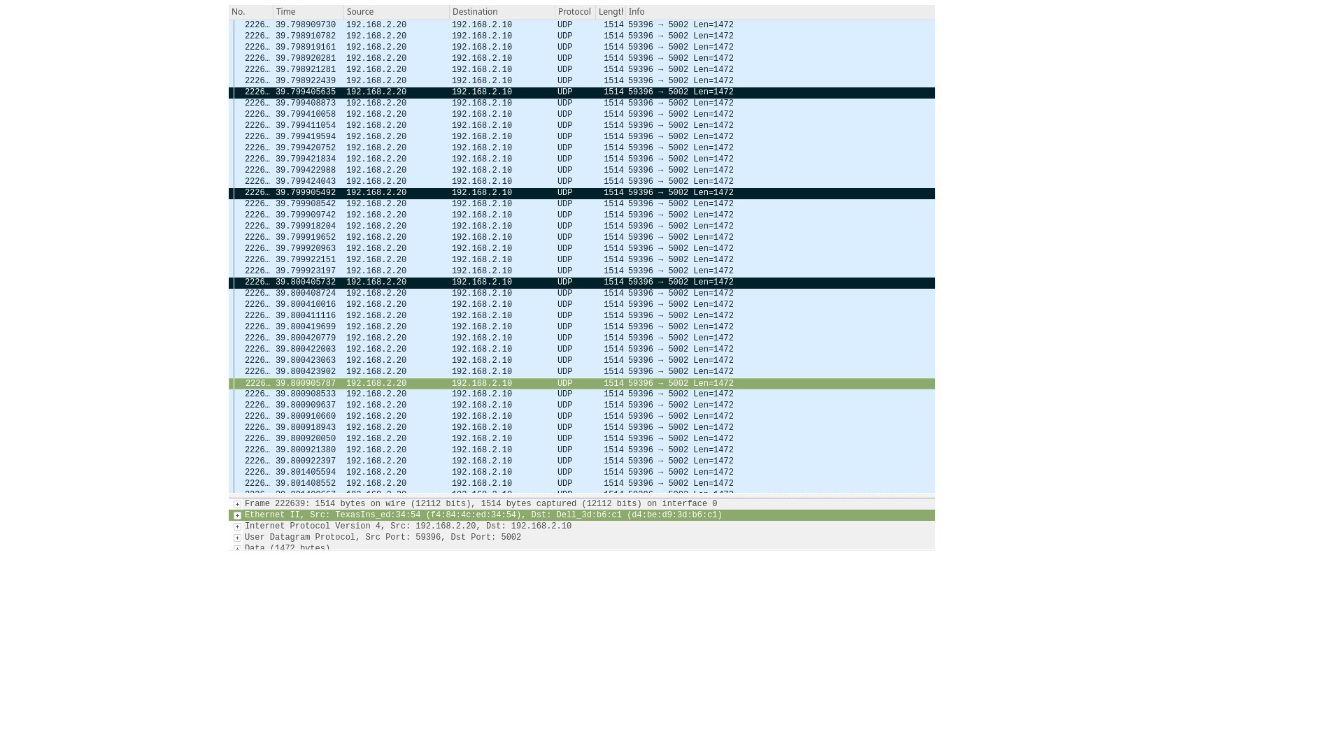
Packet highlighted are the first packet transmitted during Gate open of Q2/TC2 and are spaced apart by about 500 msec which is the cycle-time of the TAS schedule. Also there are about 9 packets transmitted during the window which is about 12 * 9 = 108 usec within the Gate open interval of 125 usec.
Guard band
CPSW2g EST H/W will transmit the frame during Gate open. If a frame happens to arrive at the h/w queue just before the Gate closes, it gets spilled over to the next schedule window. If this is not desirable, user may add a guard band between schedule window, duration of which should equal to the transmission time of a MTU frame (1518 * 8 = 12144 nsec) + 2336 nsec (TRM describes this as 292 wire clocks = 292 * 8 = 2336). This ensures that frames don’t spill over to the next sched window. For example, for the example schedule described above, to ensure no spill over, guard bands may be introduced as follows:-
tc qdisc replace dev eth0 parent root handle 100 taprio \
   num_tc 3 \
   map 0 0 1 2 0 0 0 0 0 0 0 0 0 0 0 0 \
   queues 1@0 1@1 1@2 \
   base-time 0000 \
   sched-entry S 4 110520 \
   sched-entry S 0 14480  \
   sched-entry S 2 110520 \
   sched-entry S 0 14480  \
   sched-entry S 1 235520 \
   sched-entry S 0 14480  \
   flags 2
The above schedule still have a cycle-time of 500 msec, however there are guard bands inserted between Gate Close/Open and uses 0 Gate mask during the period of 12144 usec.
cycle-time
In the example schedule described earlier, there are 3 schedule windows described by sched-entry, first 2 being each of 125 usec and a third of 250 usec. So the schedule has a cycle-time of 500 msec which is the sum of the intervals of individual schedule. tc command also allow user to specify cycle-time as part of the command which can be used to truncate or stretch an entry. For example in the typical schedule, if user specify cycle-time of 600000
tc qdisc replace dev eth0 parent root handle 100 taprio \
   num_tc 3 \
   map 0 0 1 2 0 0 0 0 0 0 0 0 0 0 0 0 \
   queues 1@0 1@1 1@2 \
   base-time 0000 \
   sched-entry S 4 110520 \
   sched-entry S 0 14480  \
   sched-entry S 2 110520 \
   sched-entry S 0 14480  \
   sched-entry S 1 235520 \
   sched-entry S 0 14480  \
   cycle-time 600000 \
   flags 2
In the above example, the last window gets stretched for a total of 350 usec instead of 250 usec resulting in a cycle-time of 600 usec. Similarly if the cycle-time is less than the sum of individual sched-entry, then schedule would get truncated.
tc qdisc replace dev eth0 parent root handle 100 taprio \
   num_tc 3 \
   map 0 0 1 2 0 0 0 0 0 0 0 0 0 0 0 0 \
   queues 1@0 1@1 1@2 \
   base-time 0000 \
   sched-entry S 4 110520 \
   sched-entry S 0 14480  \
   sched-entry S 2 110520 \
   sched-entry S 0 14480  \
   sched-entry S 1 235520 \
   sched-entry S 0 14480  \
   cycle-time 400000 \
   flags 2
In the above case, last sched-entry will become truncated to 150 usec resulting in a cycle-time of 400 usec. Also it takes about 16 wireside clock cycles (128 nsec) to fetch the sched-entry from the fetch ram. So that determines the minimum value of sched-entry interval. If it is less than this, packet spills over to the next window.
Admin command
- 802.1Q standard describes admin as a way for operator to switch to a new schedule while there is an existing (oper) schedule running. In Linux this is done by sending another tc command while one is running. A limited admin command support is provided by driver with following constraints:-
- cycle-time of the new schedule must match that of the existing schedule
- start-time must be in the past
Not supported features
- Admin command with cycle-time different from oper schedule
- Admin command at a future time
- AdminCycleTimeExtension/OperCycleTimeExtension
- Configuring of queueMaxSDUTable
- Configuring of ConfigChange
- Show ConfigPending status (tc command shows Oper and Admin schedule. So if admin schedule shows up, user application may consider this as ConfigPending)
- Show ConfigChangeError
- Show SupportedListMax - Maximum supported is 64 sched-entries if interval is < 128 usec)
3.2.2.10.4.4. Intersperse Express Traffic (IET) Frame Preemption offload
Caution
The IET configuration interface could be changed significantly in the future depending on Linux Kernel mainline development.
CPSW2g h/w support Intersperse Express Traffic (IET, defined in P802.3br/D2.0 spec which later is included in IEEE 802.3 2018) Frame preemption (FPE) feature and also to allow MAC layer to Verify if the peer supports IET MAC merge layer or not. MAC merge layer is responsible for preempting the transmission of frame from a preemptible queue if there is frame waiting for transmission at a higher priority Express queue. The h/w sends an initial segment of the frame satisfying min fragment size requirement and then schedule frame from the Express queue for transmission. Finally when no more frames available at the Express queue, it will resume transmission of remaining segments of the frame of the preemptible queue which was preempted. At the peer end, the segments are re-assembled and delivered to the MAC interface.
IET FPE feature is configured for a port through ethtool –set-priv-flags command. Note that this is a temporary interface to allow configure IET FPE in CPSW2g driver and is not approved by netdev subsystem maintainers in Linux Kernel Mailing List (LKML) and may change in the future. Driver configures IET FPE for a port when network device is opened (ndo_open()) if user has turned ON the iet-frame-preemption priv flag. Note that since IET is a common feature applicable to all slave ports, this has to be done before the network ports of the CPSW2g are brought up. The user may also turn ON the iec-mac-verify flag if the peer device connected to CPSW2g port is also capable of verifying MAC merge/FPE capability. For this, driver schedules a worker thread to do the MAC/Verify process as soon as the Link is up and iec-mac-verify priv flag is set. It resets the LINKFAIL bit and check if the Verify succeeds or not. On failure, the MAC Verify state machine is reset by toggling LINKFAIL bit and process repeats for 20 times before bailing out. If iec-mac-verify priv flag is not set, driver assumes that peer is capable of supporting FPE, but not able to do MAC Verify. So it configures the device into force mode. User needs to verify that peer device is capable of supporting IET FPE to use force mode.
Driver assumes highest priority h/w Queue as the express Queue and configures lower queues (Q0-QN-2, where N is the maximum number of queues configured) as preemptible queues by programming the PN_REG_IET_CTRL register if the MAC Verify succeeds or if the force mode is enabled. p0-rx-ptype-rrobin flag should be turned off before using IET feature. i.e CPSW2g h/w should be programmed into strict priority mode for IET to work.
To enable IET FPE with MAC Verify, do
ethtool --set-priv-flags eth0 p0-rx-ptype-rrobin off
ethtool --set-priv-flags eth0 iet-frame-preemption on
ethtool --set-priv-flags eth0 iet-mac-verify on
To enable IET FPE with no MAC Verify (Force mode)
ethtool --set-priv-flags eth0 p0-rx-ptype-rrobin off
ethtool --set-priv-flags eth0 iet-frame-preemption on
To disable IET FPE and restore rrobin mode
ethtool --set-priv-flags eth0 iet-frame-preemption off
ethtool --set-priv-flags eth0 iet-mac-verify off
ethtool --set-priv-flags eth0 p0-rx-ptype-rrobin on
Example session to enable IET FPE with MAC Verify.
Assume 2 AM65x IDKs are connected back to back over MCU Ethernet port (typically eth0 interface. Example assumes 2 h/w queues configured. Q1 will be express queue and Q0 the preemption queue in this configuration.
root@am65xx-evm:~# ip link set dev eth0 down
[  169.798571] am65-cpsw-nuss 46000000.ethernet eth0: Link is Down
root@am65xx-evm:~# ethtool -L eth0 tx 2
root@am65xx-evm:~# ethtool -l eth0
Channel parameters for eth0:
Pre-set maximums:
RX:             1
TX:             8
Other:          0
Combined:       0
Current hardware settings:
RX:             1
TX:             2
Other:          0
Combined:       0
@am65xx-evm:~# ethtool --set-priv-flags eth0 p0-rx-ptype-rrobin off
root@am65xx-evm:~# ethtool --set-priv-flags eth0 iet-frame-preemption on
root@am65xx-evm:~# ethtool --show-priv-flags eth0
Private flags for eth0:
p0-rx-ptype-rrobin  : off
iet-frame-preemption: on
iet-mac-verify      : off
root@am65xx-evm:~# ethtool --set-priv-flags eth0 iet-mac-verify on
root@am65xx-evm:~# ethtool --show-priv-flags eth0
Private flags for eth0:
p0-rx-ptype-rrobin  : off
iet-frame-preemption: on
iet-mac-verify      : on
root@am65xx-evm:~# ip link set dev eth0 up
root@am65xx-evm:~#
root@am65xx-evm:~# [  267.393967] IPv6: ADDRCONF(NETDEV_CHANGE): eth0: link becomes ready
[  267.400353] am65-cpsw-nuss 46000000.ethernet eth0: Starting IET/FPE MAC Verify
[  267.465086] am65-cpsw-nuss 46000000.ethernet eth0: IET/FPE MAC Verify Success
[  267.472276] am65-cpsw-nuss 46000000.ethernet eth0: Link is Up - 1Gbps/Full - flow control off
Example session to enable IET FPE with no MAC Verify (Force mode)
root@am65xx-evm:~# ip link set dev eth0 down
[  394.590576] am65-cpsw-nuss 46000000.ethernet eth0: Link is Down
root@am65xx-evm:~# ethtool --set-priv-flags eth0 iet-frame-preemption on
#if iet-mac-verify was enabled before, turn it off
root@am65xx-evm:~# ethtool --set-priv-flags eth0 iet-mac-verify off
root@am65xx-evm:~# ethtool --show-priv-flags eth0
Private flags for eth0:
p0-rx-ptype-rrobin  : off
iet-frame-preemption: on
iet-mac-verify      : off
root@am65xx-evm:~#
root@am65xx-evm:~# ip link set dev eth0 up
root@am65xx-evm:~# ip addr add 192.168.100.20/24 dev eth0
[  500.502660] TI DP83867 46000f00.mdio:00: attached PHY driver [TI DP83867] (mii_bus:phy_addr=46000f00.mdio:00, irq=POLL)
root@am65xx-evm:~# [  500.516232] am65-cpsw-nuss 46000000.ethernet eth0: Link is Down
root@am65xx-evm:~# [  552.738077] am65-cpsw-nuss 46000000.ethernet eth0: IET Enable Force mode
[  552.744839] am65-cpsw-nuss 46000000.ethernet eth0: Link is Up - 1Gbps/Full - flow control off
[  552.753434] IPv6: ADDRCONF(NETDEV_CHANGE): eth0: link becomes ready
IET FPE example
Highest priority Queue is Express queue. I.e if there are 8 queues configured through ethtool -L command, Q7 will be express and Q0-Q6 will be preemptible. Similarly if 4 queues are configured then Q3 will be express queue and Q0-Q2 will be preemptible queues. See below an example on how to verify preemption is happening in the hardware. Setup requires 2 IDKs (Example AM65x) connected over MCU Ethernet/CPSW2g port. Assume that IET is enabled on both IDKs as in previous sections and either Force mode or MAC Verify mode is enabled. As soon as the Link comes up, the IET FPE gets enabled. The test requires MQPRIO qdisc to be configured at the Talker DUT’s eth0 port and enable classifier to map UDP frames with specific port to be to a given traffic class. Traffic class is used as the index to direct traffic to the specific h/w queue. CPSW2g stats module provide a statistics counter for following that can be used to verify the IET FPE is functional:-
- iet_rx_assembly_ok - Increments at the receiver if re-assembly of MAC fragments are successful.
- iet_rx_frag - Incremenets at the receiver if MAC fragments are received due to preemption
- iet_tx_frag - Increments at the sender side if fragments are created due to frame preemption.
So to test, need to have traffic at the preemption queue as well as at the express queue and use the above statistics counters to verify if fragmentation happens at the sender side and re-assembly at the receiver side. Below logs provide some example usage.
# At the Talker side
# Set up mqprio qdisc at eth0 - 2 Queues configured. Q0 - preemption queue and Q1 express queue
root@am65xx-evm:~# tc qdisc replace dev eth0 handle 100: parent root mqprio num_tc 2  map 0 0 0 1 0 0 0 0 0 0 0 0 0 0 0 0 queues 1@0
1@1 hw 0
root@am65xx-evm:~# tc -g class show dev eth0
+---(100:ffe1) mqprio
|    +---(100:2) mqprio
|
+---(100:ffe0) mqprio
    +---(100:1) mqprio
# Enable classifier at net core
root@am65xx-evm:~# tc qdisc add dev eth0 clsact
# Add tc filter rule to mark packet priority based on destination UDP port number - Port 5002 mapped to prio 2
# From above mqprio settings, TC at index 2 is 0. So this TC packets go to Q0
root@am65xx-evm:~# tc filter add dev eth0 egress protocol ip prio 1 u32 match ip dport 5002 0xffff action skbedit priority 2
[  285.576105] u32 classifier
[  285.578910]     input device check on
[  285.582640]     Actions configured
# Add tc filter rule to map packets with UDP port number - Port 5003 to prio 3
# From above mqprio settings, TC at index 3 is 1. So this TC packets go to Q1
root@am65xx-evm:~# tc filter add dev eth0 egress protocol ip prio 1 u32 match ip dport 5003 0xffff action skbedit priority 3
root@am65xx-evm:~#
root@am65xx-evm:~# ip addr add 192.168.100.20/24 dev eth0

# At the Listener DUT, setup ip address and run iperf3 server session listening to port 5002 and 5003.
# ip addr add 192.168.100.30/24 dev eth0
root@am65xx-evm:~# iperf3 -s -i30 -p5002&
[1] 1224
root@am65xx-evm:~# iperf3 -s -i30 -p5003&
-----------------------------------------------------------
Server listening on 5002
-----------------------------------------------------------
[2] 1225
-----------------------------------------------------------
Server listening on 5003
-----------------------------------------------------------
root@am65xx-evm:~#
# At Listener DUT start iperf3 client session to port 5002 and 5003
root@am65xx-evm:~# iperf3 -c 192.168.100.30 -u -b200M -l1472 -u -t30 -i30 -p5002&
[1] 1050
root@am65xx-evm:~# iperf3 -c 192.168.100.30 -u -b50M -l1472 -u -t30 -i30 -p5003&
[2] 1051
root@am65xx-evm:~#
root@am65xx-evm:~# warning: UDP block size 1472 exceeds TCP MSS 1448, may result in fragmentation / drops
warning: UDP block size 1472 exceeds TCP MSS 1448, may result in fragmentation / drops
Connecting to host 192.168.100.30, port 5003
Connecting to host 192.168.100.30, port 5002
[  5] local 192.168.100.20 port 60646 connected to 192.168.100.30 port 5003
[  5] local 192.168.100.20 port 39515 connected to 192.168.100.30 port 5002

# Now at the Talker DUT, dump statistics counter for Q0 and Q1 as well as IET statistics
root@am65xx-evm:~# ethtool -S eth0 | grep 'tx_pri1'
    p0_tx_pri1: 0
    p0_tx_pri1_bcnt: 0
    p0_tx_pri1_drop: 0
    p0_tx_pri1_drop_bcnt: 0
    tx_pri1: 24869
    tx_pri1_bcnt: 37722660
    tx_pri1_drop: 0
    tx_pri1_drop_bcnt: 0
root@am65xx-evm:~# ethtool -S eth0 | grep 'tx_pri0'
    p0_tx_pri0: 0
    p0_tx_pri0_bcnt: 0
    p0_tx_pri0_drop: 0
    p0_tx_pri0_drop_bcnt: 0
    tx_pri0: 100271
    tx_pri0_bcnt: 152067960
    tx_pri0_drop: 0
    tx_pri0_drop_bcnt: 0
root@am65xx-evm:~# ethtool -S eth0 | grep iet
    iet_rx_assembly_err: 0
    iet_rx_assembly_ok: 0
    iet_rx_smd_err: 0
    iet_rx_frag: 0
    iet_tx_hold: 0
    iet_tx_frag: 159
root@am65xx-evm:~# ethtool -S eth0 | grep 'tx_pri1'
    p0_tx_pri1: 0
    p0_tx_pri1_bcnt: 0
    p0_tx_pri1_drop: 0
    p0_tx_pri1_drop_bcnt: 0
    tx_pri1: 27718
    tx_pri1_bcnt: 42047442
    tx_pri1_drop: 0
    tx_pri1_drop_bcnt: 0
root@am65xx-evm:~# ethtool -S eth0 | grep 'tx_pri0'
    p0_tx_pri0: 0
    p0_tx_pri0_bcnt: 0
    p0_tx_pri0_drop: 0
    p0_tx_pri0_drop_bcnt: 0
    tx_pri0: 111637
    tx_pri0_bcnt: 169320030
    tx_pri0_drop: 0
    tx_pri0_drop_bcnt: 0
root@am65xx-evm:~# ethtool -S eth0 | grep iet
    iet_rx_assembly_err: 0
    iet_rx_assembly_ok: 0
    iet_rx_smd_err: 0
    iet_rx_frag: 0
    iet_tx_hold: 0
    iet_tx_frag: 175

# As seen, iet_tx_frag statistics counter increments at the Talker showing fragmentation at the Talker
# Also dump the statistics at the listener DUT
ethtool -S eth0 | grep iet
    iet_rx_assembly_err: 0
    iet_rx_assembly_ok: 248
    iet_rx_smd_err: 0
    iet_rx_frag: 248
    iet_tx_hold: 0
    iet_tx_frag: 0
root@am65xx-evm:~# ethtool -S eth0 | grep iet
    iet_rx_assembly_err: 0
    iet_rx_assembly_ok: 252
    iet_rx_smd_err: 0
    iet_rx_frag: 252
    iet_tx_hold: 0
    iet_tx_frag: 0
root@am65xx-evm:~# ethtool -S eth0 | grep iet
    iet_rx_assembly_err: 0
    iet_rx_assembly_ok: 252
    iet_rx_smd_err: 0
    iet_rx_frag: 252
    iet_tx_hold: 0
    iet_tx_frag: 0
# As seen, iet_rx_frag and iet_rx_assembly_ok statistics counter increments at the Listener showing re-assembly at the Listener
Using IET together with EST
Express and preemption queues/Gates may be used as part of the EST schedule. If only Preemption queues are in a schedule entry, preceding an entry with Express queue, the guard band requirement reduces to 2048 nsec (0x100 = 256 * 8) so that packets don’t spill over to the next sched-entry. Otherwise, the guard band required is as explained in the EST section.
3.2.2.10.4.5. Forwarding and Queuing Enhancements for Time-Sensitive Streams (FQTSS, 802.1Qav)
The K3 CPSW HW supports 2 level of traffic 802.1Qav shapers which are bound to TX CPPI channels on Host P0 (CPPI Receive thread) and External Ports FIFOs which represent HW traffic classes. The HW shapers allows to configure Committed Information Rate (guaranteed) and Excess Information Rate (non guaranteed) per TX CPPI channels or External Ports Fifos.
The CPSWxG driver allows to perform Traffic Rate Limiting/shaping at:
- Host port ingress, CPPI Port Receive Rate Limiting, by configuring per TX CPPI channels shaper. Only committed information rate is supported.
- Switch egress, Ethernet Port Transmit Rate Limiting, by configuring per TX FIFO shaper. Both committed and excess information rate is supported.
The number Host port TX CPPI channels is configurable (up to 8) through ethtool commands:- -L. The Host port TX CPPI channels processing mode has to be switched in Fixed priority mode through ethtool commands: –set-priv-flags. Also note that –set-priv-flags and -L ethtool commands can be execute only when all Ethernet interfaces are down.
The Linux TC MQPRIO Qdisc can be used for mapping of packet priorities to traffic classes and routing packets to dedicated TX CPPI channels or External Ports FIFOs.
3.2.2.10.4.5.1. Host port ingress, CPPI Port Receive Rate Limiting offload
The netdev sysfs tx_maxrate parameter can be used to configure rate limit in Mbit/s per TX CPPI channel. The rate for shapers has to be set a little bit more then potential incoming rate, and real rates can differ, due to discreetness.
echo 100 > /sys/class/net/eth2/queues/tx-7/tx_maxrate
Host port ingress, CPPI Port Receive Rate Limiting offload example
In this example Rate Limiting is enabled only for Host port TX channels.
- tc filters are used to assign pri for iperf3 traffic using port as filter value
- pri7 traffic routed to TX CPPI channel 7, rate limit 100Mbit
- pri6 traffic routed to TX CPPI channel 6, rate limit 200Mbit
- pri0-5 traffic routed to TX CPPI channel 0
ip link set dev eth0 down
ethtool -L eth0 tx 8
ip link set dev eth0 up

tc qdisc replace dev eth0 handle 100: parent root mqprio num_tc 3 \
map 0 0 0 0 0 0 1 2 0 0 0 0 0 0 0 0 queues 1@0 1@6 1@7 hw 0

echo 106 > /sys/class/net/eth0/queues/tx-7/tx_maxrate
echo 212 > /sys/class/net/eth0/queues/tx-6/tx_maxrate

tc qdisc add dev eth0 clsact
tc filter add dev eth0 egress protocol ip prio 1 u32 match ip dport 5001 0xffff action skbedit priority 7
tc filter add dev eth0 egress protocol ip prio 1 u32 match ip dport 5002 0xffff action skbedit priority 6

iperf3 -c 192.168.1.2 -t10 -p5001 -Tpri7 & \
iperf3 -c 192.168.1.2 -t10 -p5002 -Tpri6 & \
iperf3 -c 192.168.1.2 -t10 -p5003 -Tpri0

#result
pri0:  - - - - - - - - - - - - - - - - - - - - - - - - -
pri0:  [ ID] Interval           Transfer     Bitrate         Retr
pri0:  [  5]   0.00-10.00  sec   767 MBytes   644 Mbits/sec    0             sender
pri0:  [  5]   0.00-10.00  sec   766 MBytes   642 Mbits/sec                  receiver

pri6:  - - - - - - - - - - - - - - - - - - - - - - - - -
pri6:  [ ID] Interval           Transfer     Bitrate         Retr
pri6:  [  5]   0.00-10.00  sec   238 MBytes   200 Mbits/sec    0             sender
pri6:  [  5]   0.00-10.01  sec   238 MBytes   199 Mbits/sec                  receiver

pri7:  - - - - - - - - - - - - - - - - - - - - - - - - -
pri7:  [ ID] Interval           Transfer     Bitrate         Retr
pri7:  [  5]   0.00-10.00  sec   120 MBytes   101 Mbits/sec    0             sender
pri7:  [  5]   0.00-10.01  sec   119 MBytes  99.9 Mbits/sec                  receiver

#statistic
tx_pri0: 2819633
tx_pri1: 2
tx_pri2: 0
tx_pri3: 102
tx_pri4: 26
tx_pri5: 0
tx_pri6: 847449
tx_pri7: 1237148
3.2.2.10.4.5.2. Switch egress, Ethernet Port Transmit Rate Limiting offload
The Linux MQPRIO Qdisc in channel offload mode can be used for mapping of packet priorities to traffic classes and configuring rate limit in Mbit/s per External Ports FIFOs. The MQPRIO Qdisc shaper bw_rlimit min_rate and max_rate parameters can be used to configure External Ports FIFO shapers.
- the traffic class (TC) in terms of MQPRIO Qdisc is mapped 1:1 to External Ports FIFO. TC0 is lowest priority.
- MQPRIO Qdisk offload is expected to work with VALN/priority tagged traffic first of all and untagged traffic has to be mapped only to TC0.
- to handle properly untagged traffic from Host Port the 1:1 mapping has to be preserved between packet priority and Host TX CPPI channel used to send packet
- VALN/priority tagged packets mapped to TC0 will exit switch with VALN tag.
- if Host sends traffic to the same, rate limited External Ports FIFO then corresponding Host TX CPPI channel shapers has to be enabled and its rate has to be set equal or less than External Ports FIFO rate
- the rate for shapers has to be set a little bit more then potential incoming rate, and real rates can differ, due to discreetness.
tc qdisc add dev eth0 parent root handle 100: mqprio num_tc 3 \
map 0 0 0 0 0 0 1 2 0 0 0 0 0 0 0 0 \
queues 1@0 1@6 1@7 hw 1 mode channel \
shaper bw_rlimit min_rate 0 212mbit 106mbit max_rate 0 250mbit 150mbit
Switch egress, Ethernet Port Transmit Rate Limiting example
In this example Rate Limiting is enabled for Host port TX channels and External Ports FIFO.
- tc filters are used to assign pri for iperf3 traffic using port as filter value
- untagged traffic
- pri7 traffic routed to TX CPPI channel 7, rate limit 100Mbit
- pri6 traffic routed to TX CPPI channel 6, rate limit 200Mbit
- pri0-5 traffic routed to TX CPPI channel 0
- pri7 traffic mapped to TC2, External Ports FIFO2, cir=100Mbit, eir=150Mbit
- pri6 traffic mapped to TC1, External Ports FIFO1, cir=200Mbit, eir=250Mbit
- pri0-5 traffic mapped to TC1, External Ports FIFO0
ip link set dev eth0 down
ethtool -L eth0 tx 8
ip link set dev eth0 up

tc qdisc add dev eth0 parent root handle 100: mqprio num_tc 3 \
map 0 0 0 0 0 0 1 2 0 0 0 0 0 0 0 0 \
queues 1@0 1@6 1@7 hw 1 mode channel \
shaper bw_rlimit min_rate 0 212mbit 106mbit max_rate 0 250mbit 150mbit

echo 106 > /sys/class/net/eth0/queues/tx-7/tx_maxrate
echo 212 > /sys/class/net/eth0/queues/tx-6/tx_maxrate

tc qdisc add dev eth0 clsact
tc filter add dev eth0 egress protocol ip prio 1 u32 match ip dport 5001 0xffff action skbedit priority 7
tc filter add dev eth0 egress protocol ip prio 1 u32 match ip dport 5002 0xffff action skbedit priority 6

iperf3 -c 192.168.1.2 -t10 -p5001 -Tpri7 & \
iperf3 -c 192.168.1.2 -t10 -p5002 -Tpri6 & \
iperf3 -c 192.168.1.2 -t10 -p5003 -Tpri0

#result
pri7:  - - - - - - - - - - - - - - - - - - - - - - - - -
pri7:  [ ID] Interval           Transfer     Bitrate         Retr
pri7:  [  5]   0.00-10.00  sec   120 MBytes   100 Mbits/sec    0             sender
pri7:  [  5]   0.00-10.00  sec   119 MBytes  99.9 Mbits/sec                  receiver

pri6:  - - - - - - - - - - - - - - - - - - - - - - - - -
pri6:  [ ID] Interval           Transfer     Bitrate         Retr
pri6:  [  5]   0.00-10.00  sec   238 MBytes   200 Mbits/sec    0             sender
pri6:  [  5]   0.00-10.00  sec   238 MBytes   199 Mbits/sec                  receiver

pri0:  - - - - - - - - - - - - - - - - - - - - - - - - -
pri0:  [ ID] Interval           Transfer     Bitrate         Retr
pri0:  [  5]   0.00-10.00  sec   767 MBytes   643 Mbits/sec    0             sender
pri0:  [  5]   0.00-10.00  sec   766 MBytes   642 Mbits/sec                  receiver

#statistic
tx_pri0: 2012441
tx_pri1: 172147
tx_pri2: 259038
tx_pri3: 0
tx_pri4: 2
tx_pri5: 9
tx_pri6: 0
tx_pri7: 0
3.2.2.10.5. Errata: i2329 MDIO interface corruption (CPSW and PRUSS)
3.2.2.10.5.1. Description
It is possible that the MDIO interface of all instances of CPSW and PRUSS peripherals (if present) returns corrupt read data on MDIO reads (e.g. returning stale or previous data), or sends incorrect data on MDIO writes. It is also possible that the MDIO interface becomes unavailable until the next peripheral reset (either by LPSC reset or global device reset with reset isolation disabled in case of CPSW).
Possible system level manifestations of this issue could be (1) erroneous ethernet PHY link down status (2) inability to properly configure an ethernet PHY over MDIO (3) incorrect PHY detection (e.g. wrong address) (4) read or write timeouts when attempting to configure PHY over MDIO.
The most common issue with Linux is observation of following prints in the kernel log
am65-cpsw-nuss 46000000.ethernet eth0: Link is Down
am65-cpsw-nuss 46000000.ethernet eth0: Link is Down
am65-cpsw-nuss 46000000.ethernet eth0: Link is Up - 100Mbps/Full - flow control off
am65-cpsw-nuss 46000000.ethernet eth0: Link is Down
am65-cpsw-nuss 46000000.ethernet eth0: Link is Up - 100Mbps/Full - flow control off
am65-cpsw-nuss 46000000.ethernet eth0: Link is Down
am65-cpsw-nuss 46000000.ethernet eth0: Link is Up - 100Mbps/Full - flow control off
am65-cpsw-nuss 46000000.ethernet eth0: Link is Down
am65-cpsw-nuss 46000000.ethernet eth0: Link is Up - 100Mbps/Full - flow control off
am65-cpsw-nuss 46000000.ethernet eth0: Link is Down
am65-cpsw-nuss 46000000.ethernet eth0: Link is Up - 100Mbps/Full - flow control off
am65-cpsw-nuss 46000000.ethernet eth0: Link is Down
am65-cpsw-nuss 46000000.ethernet eth0: Link is Up - 100Mbps/Full - flow control off
am65-cpsw-nuss 46000000.ethernet eth0: Link is Down
am65-cpsw-nuss 46000000.ethernet eth0: Link is Up - 100Mbps/Full - flow control off
am65-cpsw-nuss 46000000.ethernet eth0: Link is Down
am65-cpsw-nuss 46000000.ethernet eth0: Link is Up - 100Mbps/Full - flow control off
am65-cpsw-nuss 46000000.ethernet eth0: Link is Down
am65-cpsw-nuss 46000000.ethernet eth0: Link is Up - 100Mbps/Full - flow control off
am65-cpsw-nuss 46000000.ethernet eth0: Link is Down
am65-cpsw-nuss 46000000.ethernet eth0: Link is Up - 100Mbps/Full - flow control off
am65-cpsw-nuss 46000000.ethernet eth0: Link is Down
am65-cpsw-nuss 46000000.ethernet eth0: Link is Up - 100Mbps/Full - flow control off
am65-cpsw-nuss 46000000.ethernet eth0: Link is Down
am65-cpsw-nuss 46000000.ethernet eth0: Link is Up - 100Mbps/Full - flow control off
am65-cpsw-nuss 46000000.ethernet eth0: Link is Down
am65-cpsw-nuss 46000000.ethernet eth0: Link is Up - 100Mbps/Full - flow control off
am65-cpsw-nuss 46000000.ethernet eth0: Link is Down
am65-cpsw-nuss 46000000.ethernet eth0: Link is Up - 100Mbps/Full - flow control off
am65-cpsw-nuss 46000000.ethernet eth0: Link is Down
am65-cpsw-nuss 46000000.ethernet eth0: Link is Up - 100Mbps/Full - flow control off
am65-cpsw-nuss 46000000.ethernet eth0: Link is Down
am65-cpsw-nuss 46000000.ethernet eth0: Link is Up - 100Mbps/Full - flow control off
am65-cpsw-nuss 46000000.ethernet eth0: Link is Down
am65-cpsw-nuss 46000000.ethernet eth0: Link is Up - 100Mbps/Full - flow control off
am65-cpsw-nuss 46000000.ethernet eth0: Link is Down
am65-cpsw-nuss 46000000.ethernet eth0: Link is Up - 100Mbps/Full - flow control off
3.2.2.10.5.2. Workaround for TI SDK Version > 8.4
MDIO protocol can be emulated by reading and writing to the appropriate bits within the MDIO_MANUAL_IF_REG register of the MDIO peripheral to directly manipulate the MDIO clock and data pins. Refer to TRM for full details of manual mode register bits and their function.
In this case the device pin multiplexing should be configured to allow the IO to be controlled by the CPSW or PRUSS peripherals (same as in normal intended operation), but the MDIO state machine must be disabled by ensuring MDIO_CONTROL_REG.ENABLE bit is 0 in the MDIO_CONTROL_REG and enable manual mode by setting MDIO_POLL_REG.MANUALMODE bit to 1.
The implementation of the above workaround is available from Processor SDK v8.5.