2. Getting started
2.1. Hardware setup
2.1.1. AM68A EVM
AM68A EVM is a low cost, small form factor board designed to bring smart cameras, robots and intelligent machines to life. For more information related to the board, full list of peripherals supported, pin settings for boot modes and more visit AM68A EVM User guide
To run the demos on AM68A EVM you will require,
AM68A EVM
Minimum 16GB high performance SD card
External Power Supply or Power Accessory Requirements
USB 2.0 mouse
Full-HD (1080p) HDMI display
Optional 100Base-T Ethernet cable connected to internet
Optional UART cable
Optional USB camera (Any V4L2 compliant 1MP/2MP camera, Eg. Logitech C270/C920/C922)
Nominal Output Voltage: 5-20VDC
Maximum Output Current: 5000 mA
Refer to AM68A EVM User guide for more details.
Connect the components to the EVM as shown in the image.
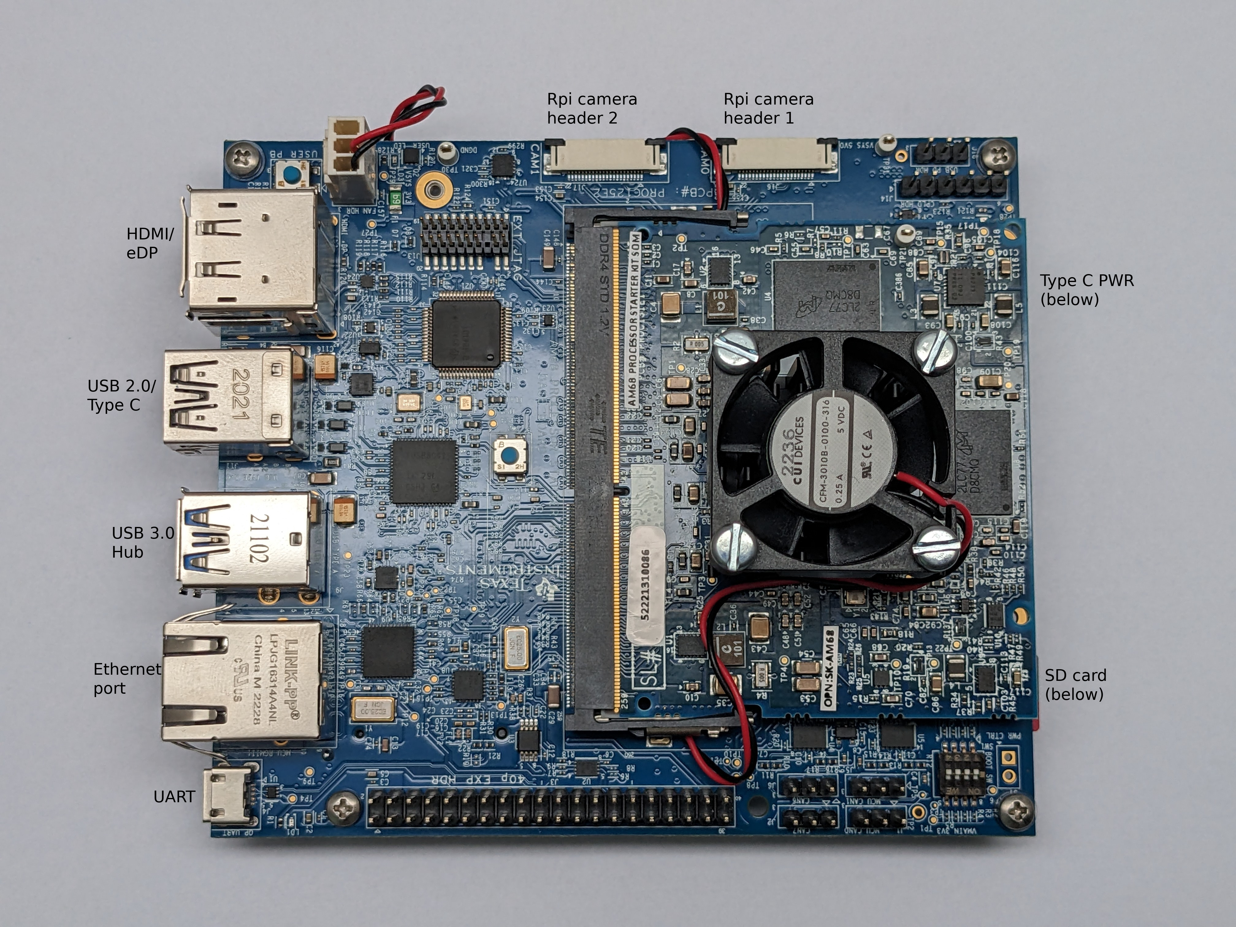
Fig. 2.1 AM68A EVM connections
Set the boot pins to SD boot mode as shown in the following image.
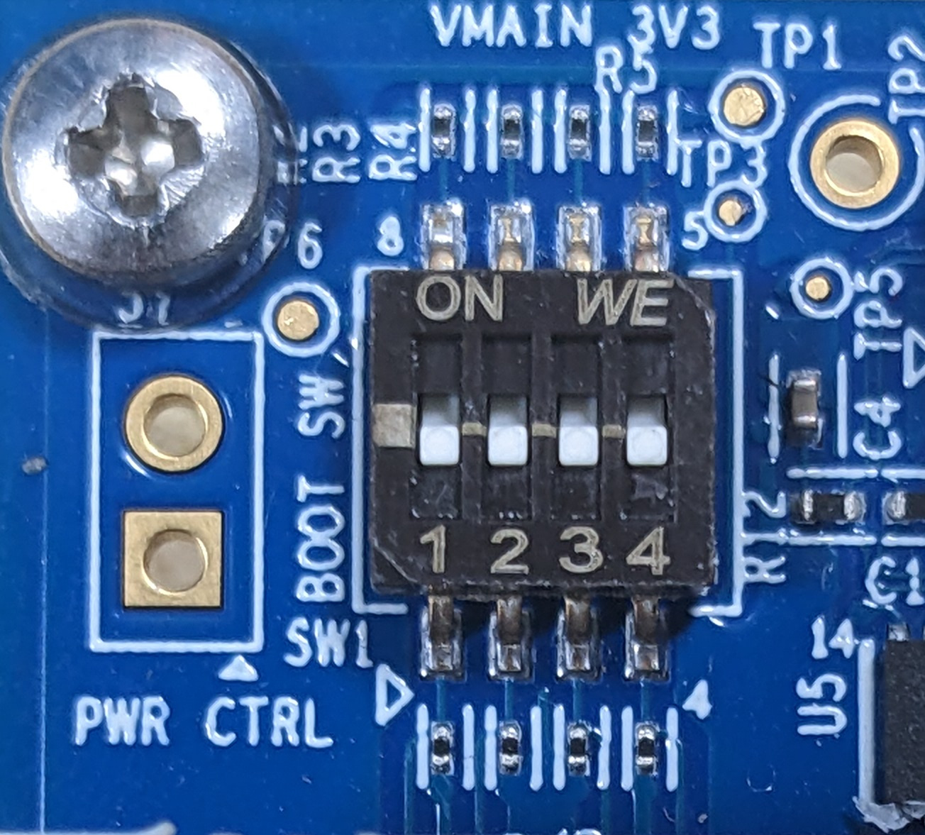
Fig. 2.2 AM68A EVM boot pins
2.1.2. USB Camera
UVC (USB video class) compliant USB cameras are supported by AM68A EVM. The driver for the same is enabled in SDK. The SDK has been tested with C270/C920/C922 versions of Logitech USB cameras. Please refer to Getting Error when trying to capture from multiple USB cameras simultaneously to stream from multiple USB cameras simultaneously.
2.1.3. RPiV2(IMX219) Raw sensor
RPiV2 camera module is supported by AM68A EVM. It is a 8MP sensor with no ISP, which can transmit raw SRGGB8 frames over CSI lanes at 1080p resolution at 30 fps.
For more details visit Rpi camera module v2
Note
For trying different resolutions of the same sensor we would also require different DCC binary files to work with tiovxisp and tiovxldc plugins.
Below is a patch posted upstream to enable other higher fps with lower resolution modes https://patchwork.linuxtv.org/project/linux-media/patch/20210115185233.333407-1-angelogioacchino.delregno@somainline.org/
The camera can be connected to the RPi header as shown below on AM68A. Note that the headers have to be lifted up to connect the cameras and put back firmly to keep the connector cable in place.
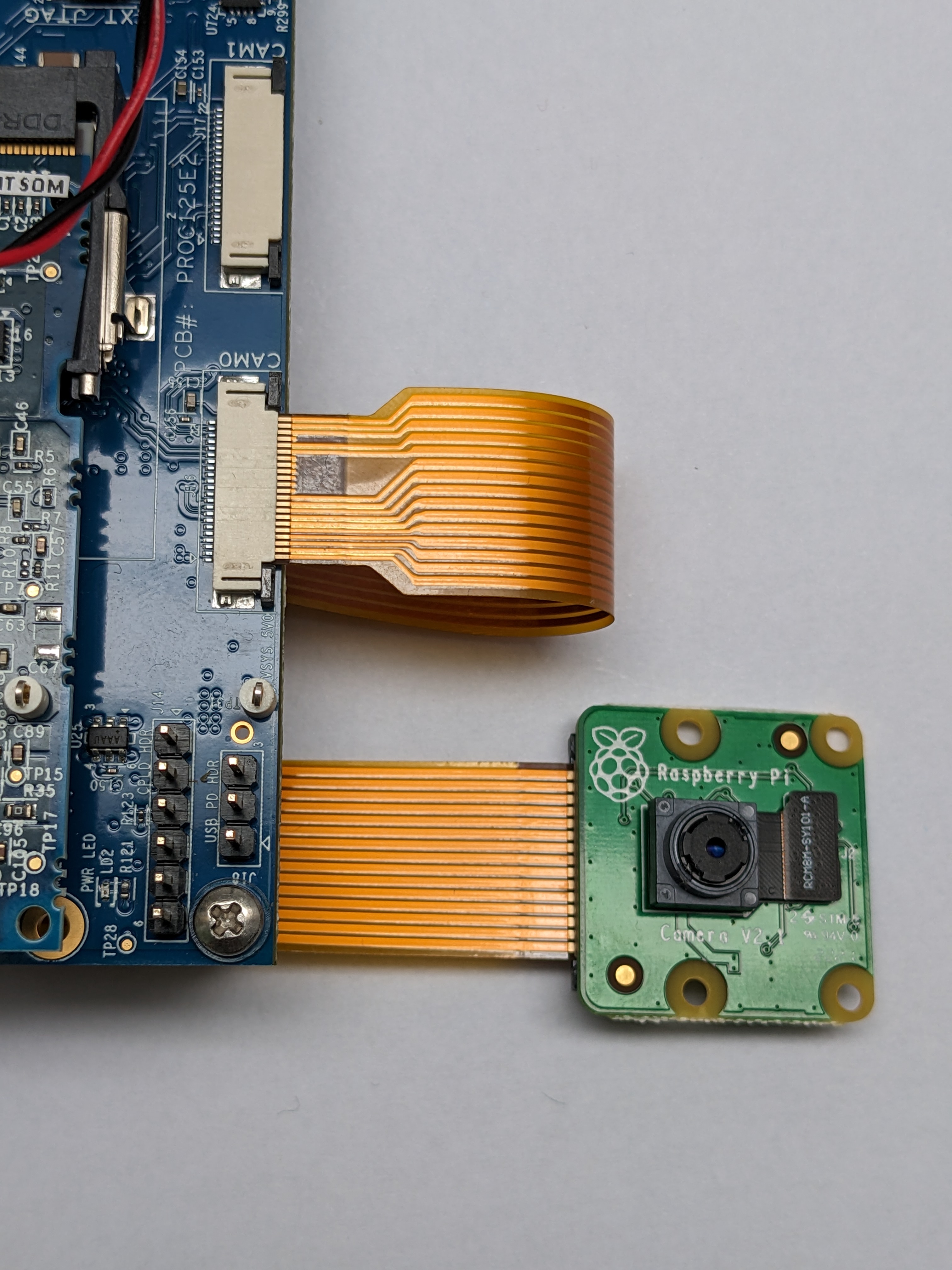
Fig. 2.3 IMX219 CSI sensor connection with AM68A EVM
Note
By default IMX219 is disabled. After connecting the camera you can enable it
by specifying the dtb overlay file in
/run/media/mmcblk1p1/uEnv.txt as below,
name_overlays=k3-j721s2-edgeai-apps.dtbo k3-am68-sk-bb-rpi-cam-imx219.dtbo
Reboot the board after editing and saving the file.Dtb files can be found under /boot.
Please refer Camera sources (v4l2) to know how to list all the cameras connected and select which one to use for the demo.
By default IMX219 will be configured to capture at 8 bit, but it also supports 10 bit capture in 16 bit container. To use it in 10 bit mode, below steps are required:
Modify the
/opt/edgeai-gst-apps/scripts/setup_cameras.shto set the format to 10 bit like belowCSI_CAM_0_FMT='[fmt:SRGGB8_1X10/1920x1080]' CSI_CAM_1_FMT='[fmt:SRGGB8_1X10/1920x1080]'
Change the imaging binaries to use 10 bit versions
mv /opt/imaging/imx219/dcc_2a.bin /opt/imaging/imx219/dcc_2a_8b.bin
mv /opt/imaging/imx219/dcc_viss.bin /opt/imaging/imx219/dcc_viss_8b.bin
mv /opt/imaging/imx219/dcc_2a_10b.bin /opt/imaging/imx219/dcc_2a.bin
mv /opt/imaging/imx219/dcc_viss_10b.bin /opt/imaging/imx219/dcc_viss.bin
Set the input format in the
/opt/edgeai-gst-apps/configs/rpiV2_cam_example.yamlasrggb10
2.2. Software setup
2.2.1. Preparing SD card image
Download the latest SD card .wic image and flash it to SD card using Balena etcher tool available at:
Note
We have tested with Balena Etcher version 1.7.0 which can be found here, https://github.com/balena-io/etcher/releases/tag/v1.7.0
There seem to be a known-issue with latest 1.7.2 version of Balena Etcher https://forums.balena.io/t/etcher-error-message-cannot-read-property-message-of-null/350471
The tool can be installed either on Windows/Linux. Just download the etcher image and follow the instructions to prepare the SD card.
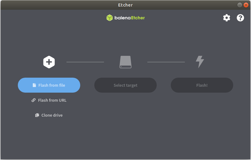
Fig. 2.4 Balena Etcher tool to flash SD card with Processor SDK Linux for AM68A
The etcher image is created for 16 GB SD cards, if you are using larger SD card, it is possible to expand the root filesystem to use the full SD card capacity using below steps on a Linux PC
#find the SD card device entry using lsblk (Eg: /dev/sdc)
#use the following commands to expand the filesystem
#Make sure you have write permission to SD card or run the commands as root

#Unmount the BOOT and rootfs partition before using parted tool
umount /dev/sdX1
umount /dev/sdX2

#Use parted tool to resize the rootfs partition to use
#the entire remaining space on the SD card
#You might require sudo permissions to execute these steps
parted -s /dev/sdX resizepart 2 '100%'
e2fsck -f /dev/sdX2
resize2fs /dev/sdX2

#replace /dev/sdX in above commands with SD card device entry
2.2.2. Power ON and Boot
Ensure that the power supply is disconnected before inserting the SD card. Once the SD card is firmly inserted in its slot and the board is powered ON, the board will take less than 20sec to boot and start running the Edge AI Gallery Application as shown
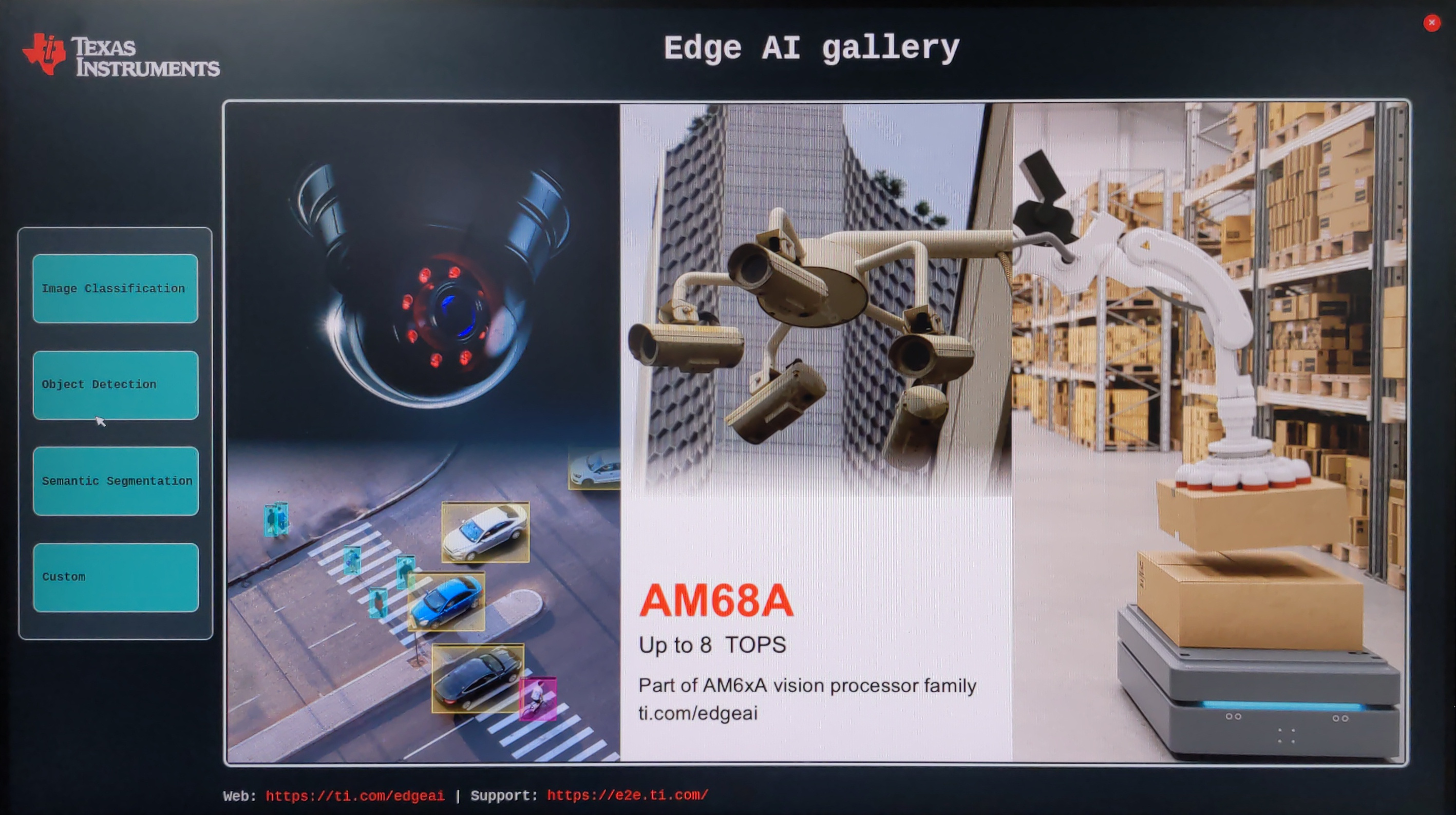
Fig. 2.5 AM68A EVM out-of-box UI demo showing wallpaper
You can also view the boot log by connecting the UART cable to your PC and use a serial port communications program. 4 serial ports will come up on your PC, you should connect to port 2 to get the boot logs
For Linux OS minicom** works well. Please refer to the below documentation on ‘minicom’ for more details.
https://help.ubuntu.com/community/Minicom
When starting minicom, turn on the colors options like below:
sudo minicom -D /dev/ttyUSB2 -c on
For Windows OS Tera Term works well. Please refer to the below documentation on ‘TeraTerm’ for more details
https://learn.sparkfun.com/tutorials/terminal-basics/tera-term-windows
Note
If using a Windows computer, the user may need to install additional drivers for ports to show up: https://www.silabs.com/developers/usb-to-uart-bridge-vcp-drivers
Note
Baud rate should be configured to 115200 bps in serial port communication program. You may not see any log in the UART console if you connect to it after the booting is complete or login prompt may get lost in between boot logs, press ENTER to get login prompt
As part of the linux systemd /opt/edgeai-gst-apps/init_script.sh is executed
which does the below,
This sets up necessary environment variables.
If any camera is connected to the board, the script sets it up and prints its device id and other information.
Once Linux boots login as root user with no password.
2.2.3. Connect remotely
If you don’t prefer the UART console, you can also access the device with the IP address that is shown on the display. With the IP address one can ssh directly to the board, view the contents and run the demos. For best experience we recommend using VSCode which can be downloaded from here,
https://code.visualstudio.com/download
You also require the “Remote development extension pack” installed in VSCode as mentioned here:
https://code.visualstudio.com/docs/remote/ssh
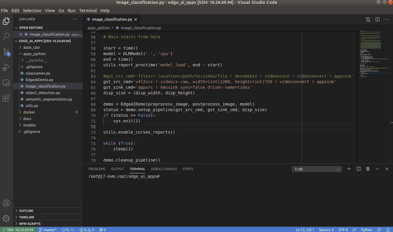
Fig. 2.6 Microsoft Visual Studio Code for connecting to AM68A EVM via SSH
If you are using Ubuntu 22.04 , add the following to ~/.ssh/config
# Add to ~/.ssh/config. Absolute IP or range of IP can be defined using *
Host 10.24.*
    HostKeyAlgorithms=+ssh-rsa
You can now SSH using terminal.
$ ssh root@10.24.69.123