Note
4.1. Introduction to AUTOSAR
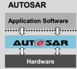
AUTOSAR (AUTomotive Open System ARchitecture) is an open and standardized automotive software architecture jointly developed by automobile manufacturers, suppliers, and tool developers. AUTOSAR focuses on main strategic targets as modularity, configurability and transferability of software modules, and the standardization of their interfaces to accomplish the project objectives.
AUTOSAR is based on the concept of separation between infrastructure and application. AUTOSAR software component implementation is independent from the infrastructure.
- Infrastructure: services providing an execution environment to abstract hardware details.
- Application: vehicle functions of interest. Consists of interconnected software components.
4.2. Overview of AUTOSAR and MCAL
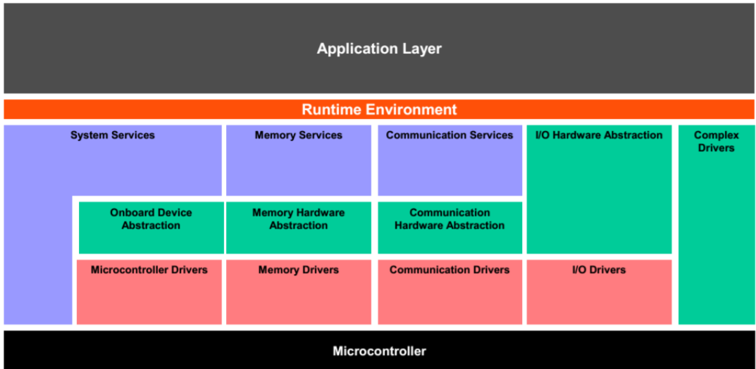
AutoSAR infrastructure consists of the following layers in the architecture:
- Runtime Environment(RTE): Middleware layer which provides communication services for the application software and makes the components independent of a specific MCU.
- Basic Software(BSW) Layer: Software layer with basic services and drivers to leverage features of the underlying hardware, and enabling interface to application and RTE layer.
- Services Layer: Offers basic services, Memory Services, Diagnostic Services, state management for components in the basic layer.
- ECU Abstraction Layer: Interfaces the drivers of MCAL and makes higher software layers independent of hardware layout and offers access to I/O signals.
- Microcontroller Abstraction Layer (MCAL): Microcontroller Abstraction Layer which is the lowest software layer designed to make higher level software independent of a microcontroller.
- Complex driver: Collection of complex sensor and actuator control or non-standardized drivers that may need migration.
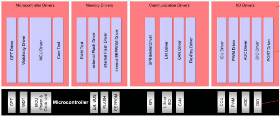
4.2.1. Overview for MCAL
MicroController Abstraction Layer (MCAL) is a software module that enables direct access to on-chip MCU peripheral modules and makes the upper software layer independent of the MCU. MCAL software modules for Hercules Safety MCUs are shown below.
4.3. Engagement Model and Software Release Process
TI does not charge for the Hercules MCAL releases. Given that the MCAL needs to be integrated with higher level AutoSAR stack, there are currently two methods in the release process.
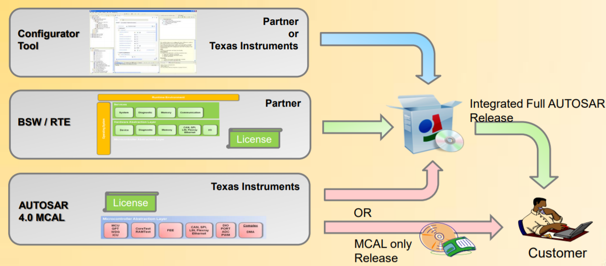
Third Party AutoSAR Provider Release (Recommended) TI works with several 3rd party partners who provide AUTOSAR packages for Hercules devices. Generally, TI released MCAL is provided to them and they produce the integrated final product that includes the BSW/RTE layers together with the TMS570 MCAL. The TMS570 MCAL is available to customers on an as-needed evaluation license on request. The primary 3rd parties we have worked with are Vector, Elektrobit, and ETAS. TI does not recommend any one supplier over another. Due to the integrated solution, this is the preferred method for customers to obtain TI MCAL with AutoSAR on Hercules.
The list of third parties is available in the section Third Party Solution for Hercules MCU on ti.com
Standalone MCAL Release (available upon request) TI can provide standalone MCAL for Hercules MCUs upon request. Please reach out to your local TI contact or post on TI E2E Forums to request standalone MCAL. Also, if there is a different AUTOSAR vendor not mentioned above that a user would prefer to use, they can post on the TI E2E to check into the plausibility of providing the MCAL to them in the same way.
4.4. Downloads and Documentation
4.4.1. Software Download
Please request access to the MCAL package for the Hercules Safety MCU that is provided through the secure software portal through TI local contact/FAE or TI E2E forums.
| Software Package | TI.com Link |
|---|---|
| AUTOSAR-MCAL-TMS570LS3X2X | Download MCAL Package for TMS570LS3X (Login Required) |
| AUTOSAR-MCAL-TMS570LS1X | Download MCAL Package for TMS570LS1X (Login Required) |
| AUTOSAR-MCAL-TMS570LS09X07X | Download MCAL Package for TMS570LS09X(Login Required) |
4.4.1.1. Modules and User Guides
| Module Category | Module | User Guide Location |
| Microcontroller Driver | GPT Driver General Purpose Timer Driver |
AUTOSAR_MCAL_<DEVICE>/GPT_TI_<DEVICE>/docs/GPT_Driver_userguide.pdf |
MCU Driver Micro Controller Unit Driver |
AUTOSAR_MCAL_<DEVICE>/MCU_TI_<DEVICE>/docs/MCU_Driver_userguide.pdf | |
WDG Driver Watch Dog Timer driver |
AUTOSAR_MCAL_<DEVICE>/WDG_TI_<DEVICE>/docs/WDG_Driver_userguide.pdf | |
| Memory Driver | FEE Driver Flash Execution Environment Driver |
AUTOSAR_MCAL_<DEVICE>/FEE_TI_<DEVICE>/docs/FEE_Driver_userguide.pdf |
| Communication Driver | SPI Driver Serial Peripheral Interface Driver | AUTOSAR_MCAL_<DEVICE>/SPI_TI_<DEVICE>/docs/SPI_Driver_userguide.pdf |
| LIN Driver Local Interconnect Network Driver | AUTOSAR_MCAL_<DEVICE>/LIN_TI_<DEVICE>/docs/LIN_Driver_userguide.pdf | |
| CAN Driver Control Area Network Driver | AUTOSAR_MCAL_<DEVICE>/CAN_TI_<DEVICE>/docs/CAN_Driver_userguide.pdf | |
| PWM Driver Micro Controller Unit Driver | AUTOSAR_MCAL_<DEVICE>/PWM_TI_<DEVICE>/docs/PWM_Driver_userguide.pdf | |
| ICU Driver Input Capture Unit Driver | AUTOSAR_MCAL_<DEVICE>/ICU_TI_<DEVICE>/docs/ICU_Driver_userguide.pdf | |
| IO Driver | ADC Driver Device Driver for onchip ADC | AUTOSAR_MCAL_<DEVICE>/ADC_TI_<DEVICE>/docs/ADC_Driver_userguide.pdf |
| DIO Driver Digital IO Driver | AUTOSAR_MCAL_<DEVICE>/DIO_TI_<DEVICE>/docs/DIO_Driver_userguide.pdf | |
| PORT Driver Port and Pin Driver | AUTOSAR_MCAL_<DEVICE>/PORT_TI_<DEVICE>/docs/PORT_Driver_userguide.pdf | |
| WDG Driver Watch Dog Timer Driver | AUTOSAR_MCAL_<DEVICE>/WDG_TI_<DEVICE>/docs/WDG_Driver_userguide.pdf |
4.5. Getting Started
Step 1: Download the AUTOSAR specification locked for the project from the AUTOSAR website.
Step 2: Get comfortable with the Software Requirement Specification (SRS) and Software Specification (SWS) for each MCAL module and derive requirements. The software requirement document must contain all requirements in SWS.
Step 3: Install the EB tresos
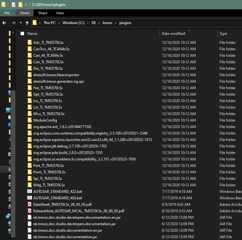
Step 4: Download MCAL6 and Install MCAL driver to EBtresosplugins
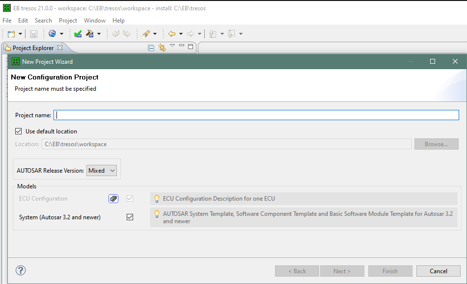
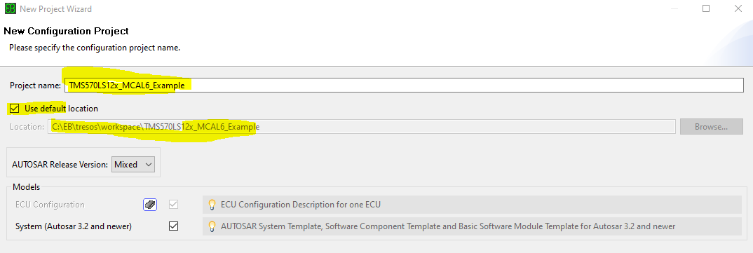
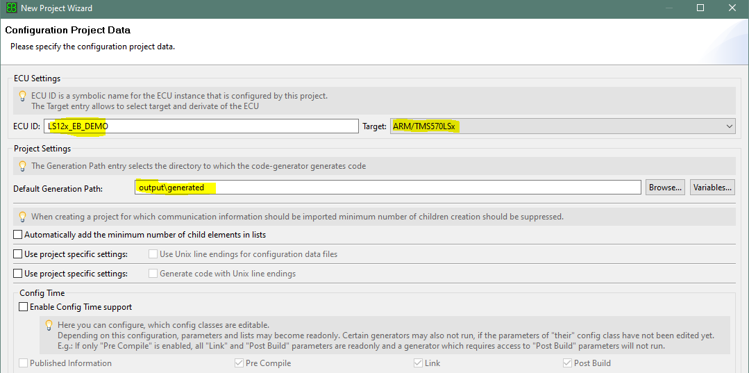
Step 5: Create a new EBresos project for TMS570
EBTresos->File->New->Configuration Project
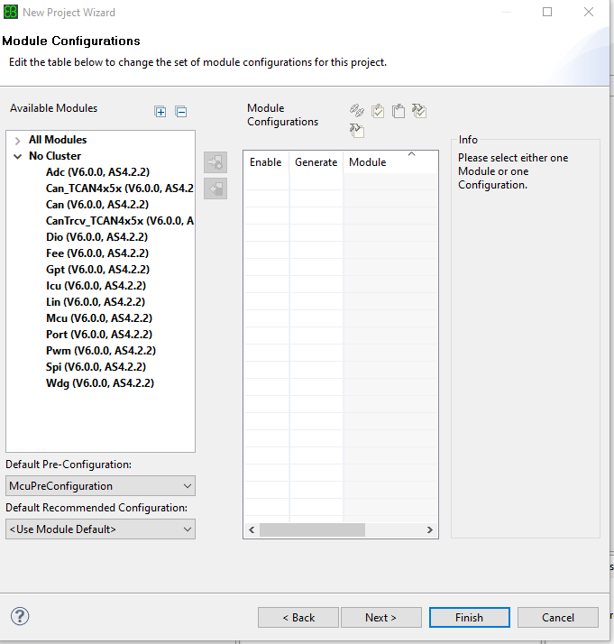
Select the modules for the project:
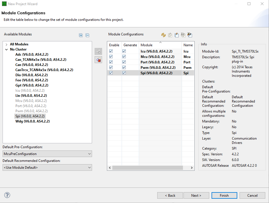
Then click “Finish”
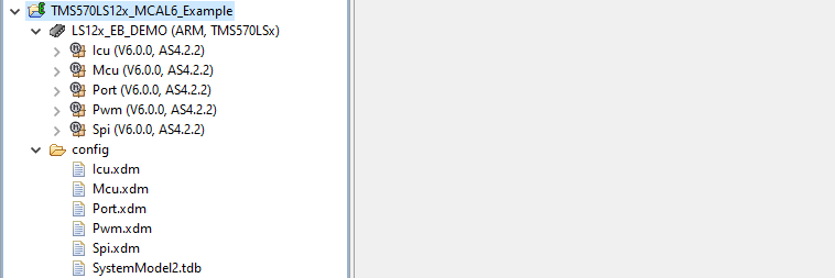
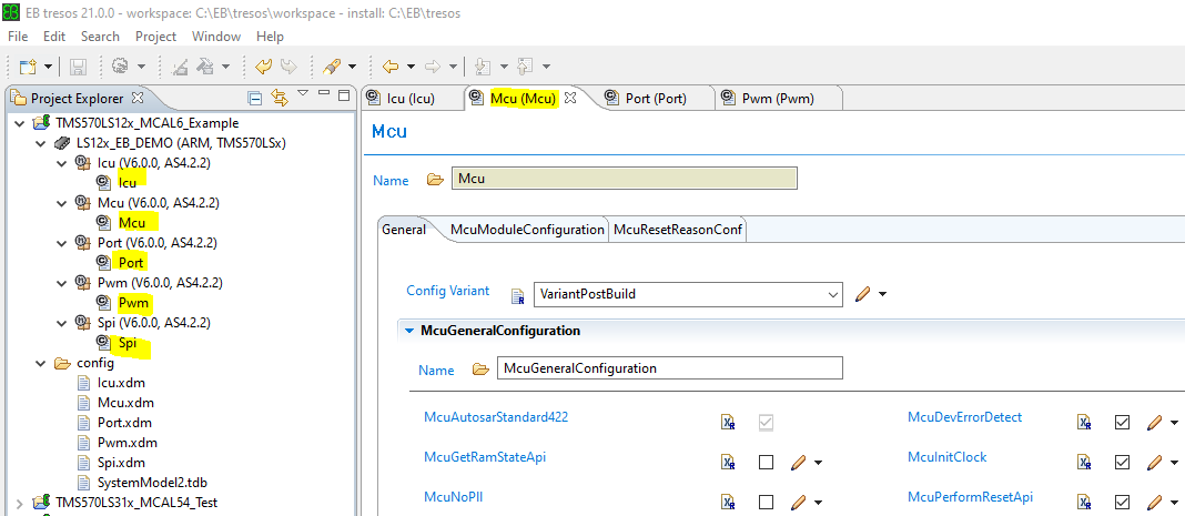
Double click the module name to configure the module
After completion of modules’ configuration, click right mouse button, select “Generate Project” to generate configuration files:
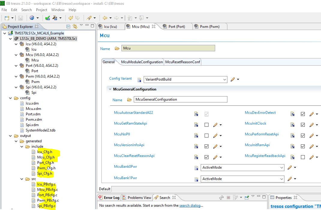
Import EB configuration files and MCAL driver to CCS project Use HALCoGen to generate the peripheral drivers Create a folder “MCAL” under CCS project folder. Then copy EB configuration files, MCAL driver etc to MCAL folder
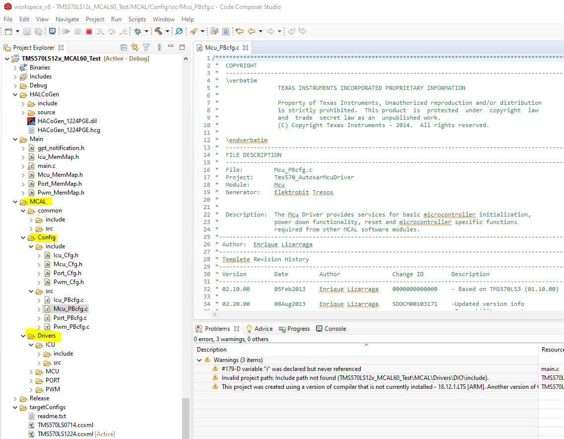
Define the Include search pathes:

Write code to call MCAL APIs:
int main(void)
{
   /* General Device Initializations */
   /* enable irq interrupt in Cortex R4 */
   _enable_interrupt_();

   setupFlash();

   /* Testing PORT MCAL */
   /* Initialize Port module for all Pin Mux related setting */
   Port_Init(&PortConfigSet_0);

   sciInit();
   sciSend(UARTPORT, 17,(uint8 *) "The test Begins");

   /* Testing PWM MCAL */
   Icu_Init(&IcuConfigSet_0);
   Pwm_Init(&PwmChannelConfigSet_0);

   while(1){
      Icu_StartSignalMeasurement(0);
      Icu_StopSignalMeasurement(0);
      Icu_GetDutyCycleValues(0, &QJ_DutyCycle0);
      duty0 = QJ_DutyCycle0.ActiveTime *100/QJ_DutyCycle0.PeriodTime;
      period0 = (QJ_DutyCycle0.PeriodTime * 128 * 12.5F) / (1000000.00F);
      Icu_StartSignalMeasurement(1);
   }
}
4.6. MCAL Modules Configuration in EB Tresos
ICU
1.1 Introduction
TMS570LS12xx have a programmable timer sub system which enables the input capturing unit (ICU). This document gives a head start into developing an ICU application using TI’s MCAL. It provides the necessary steps to configure the module in Eb tresos tool and then write an application to measure the frequency and duty cycle of an input wave.
In this note, we are using the NHET timer peripheral on the microcontroller to capture the signal. The NHET1_18 pin is selected for the input. For testing purpose, we can take the 1Khz reference signal from the oscilloscope and feed it to the NHET1_18 pin of the controller.
1.2 Configuration in Eb tool
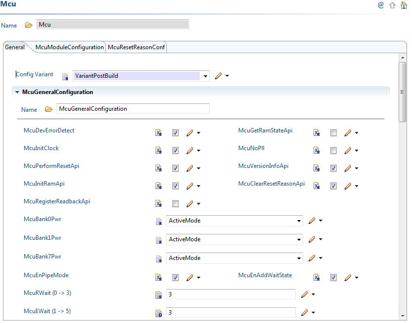
1.2.1 MCU
MCU module should be properly configured before using any peripheral.

1.2.2 PORT
The PORT module does two things. One is functionality selection and the other is pin muxing. For the ICU, we need not do any functionality selection. Only pin muxing should be taken care.
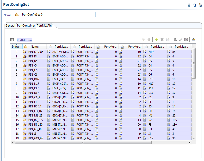
1.2.3 Pin muxing
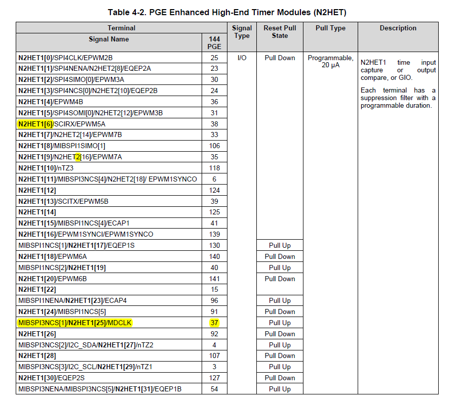
The pins used for this application are from NHET peripheral. We have selected NHET1_18 pin for the ICU input waveform. We can see from the datasheet that N2HET1_18 is the default functionality for the pin 140 of PGE package. So, we are not changing the pin muxing default.

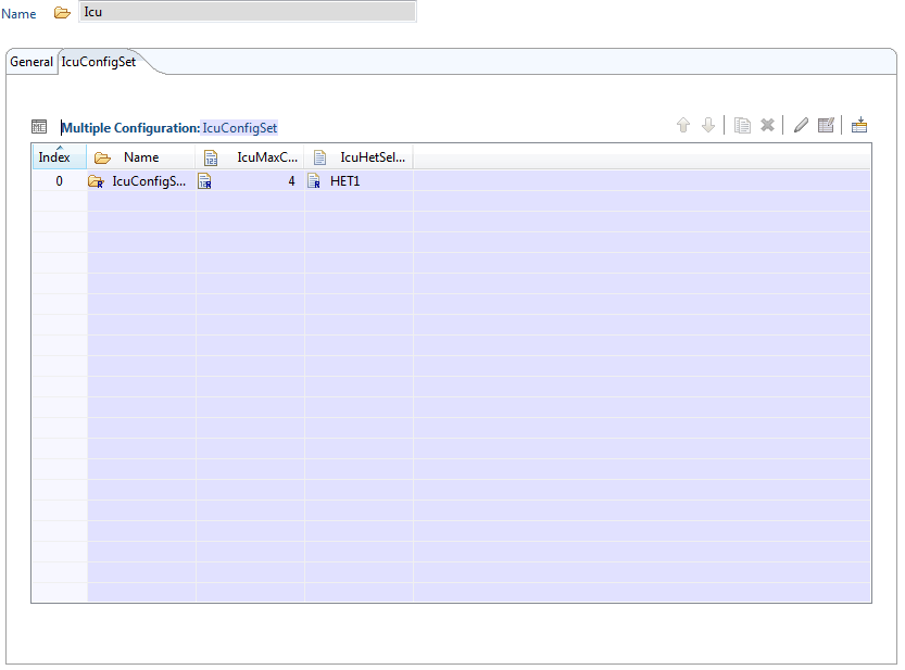
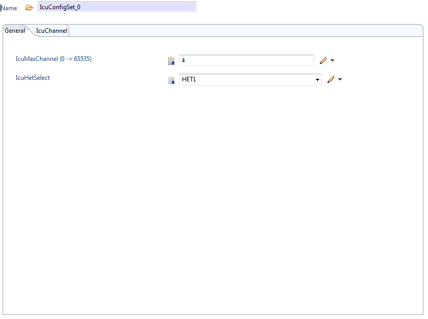
1.2.4 ICU
Configure the ICU module for capturing the frequency and dutycycle of an input wave.
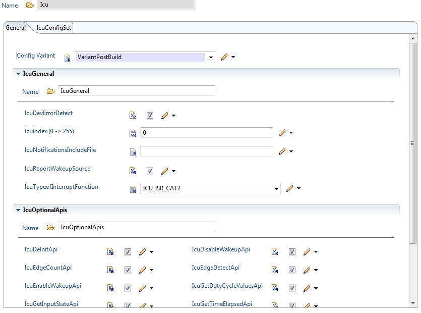
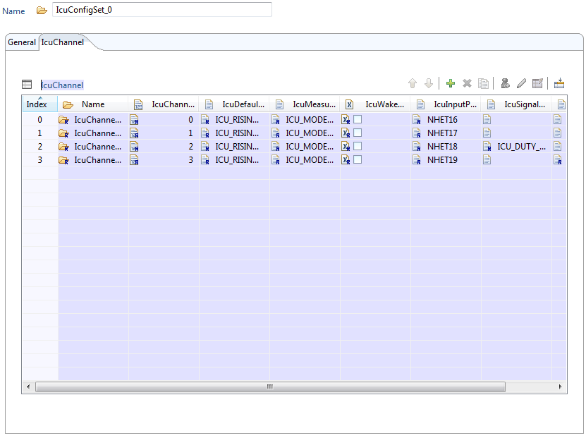
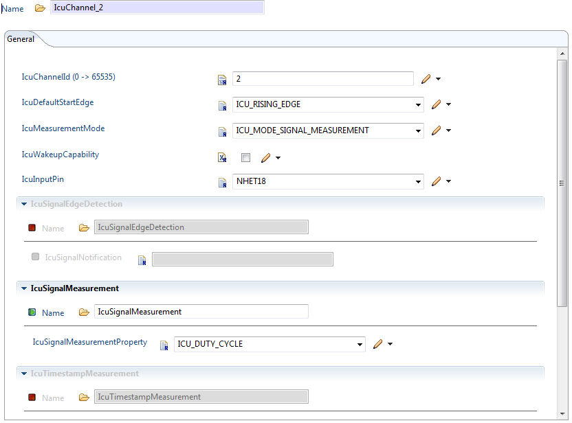
As shown in the figure, select the ICUMeasurementMode as ICU_MODE_SIGNAL_MEASUREMENT, IcuInputPin as NHET18.
1.3. Application
In this example, we are measuring the frequency and dutycycle of the input wave. The value we obtain in the ICU_DP structure has to be multiplied by the Loop resolution period (LRP) in order to get the time in seconds/ms/us.
The LRP is given by the following formula.
LRP = (hr*lr)/VCLK2
Ex: If VCLK2 is 80MHz, hr =1, lr =128
LRP = (1 * 128)/80MHz = 1.6us
#include "Mcu.h"
#include "Port.h"
#include "Pwm.h"
#include "Icu.h"

int main(void)
{
   int i;
   Icu_DutyCycleType ICU_DP;
   Mcu_Init(&McuModuleConfiguration_0);
   Port_Init(&Port_Runtime);
   Pwm_Init(&PwmChannelConfigSet_0);
   Icu_Init(&IcuConfigSet_0);
   Icu_StartSignalMeasurement(IcuChannel_2);
   while(1){
     for (i = 0; i < 100000; i++) {
        ;
     }
     Icu_GetDutyCycleValues(IcuChannel_2, &ICU_DP);
   }
   return 0;
}
PWM
2.1 Introduction
The TMS570LS12xx has a programmable timer sub system which enables Pulse width modulation (PWM). This document gives a head start into developing a PWM application using TI’s MCAL. It provides the necessary steps to configure the module in Eb tresos tool and then write an application to generate a PWM waveform.
In this section, we are using the NHET timer peripheral on the microcontroller to generate the PWM waveform. The NHET1_6 pin is selected for the output.
2.2 Configuration in Eb tresos tool
2.2.1 MCU
MCU module should be properly configured before using any peripheral.

2.2.2 PORT
The PORT module does two things. One is functionality selection and the other is pin muxing. For the PWM, we need not do any functionality selection. Only pin muxing should be taken care.

2.2.3 Pin muxing
The pins used for this application are from NHET peripheral. We have selected NHET1_6 pin for the PWM output waveform. We can see from the datasheet that N2HET1_6 is the default functionality for the pin 38 of PGE package. So, we are not changing the pin muxing default.
2.2.4 PWM
Configure the PWM module for generating a waveform with a period of 1s and 60% dutycycle.
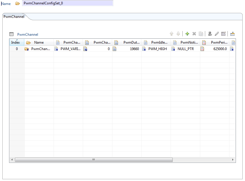
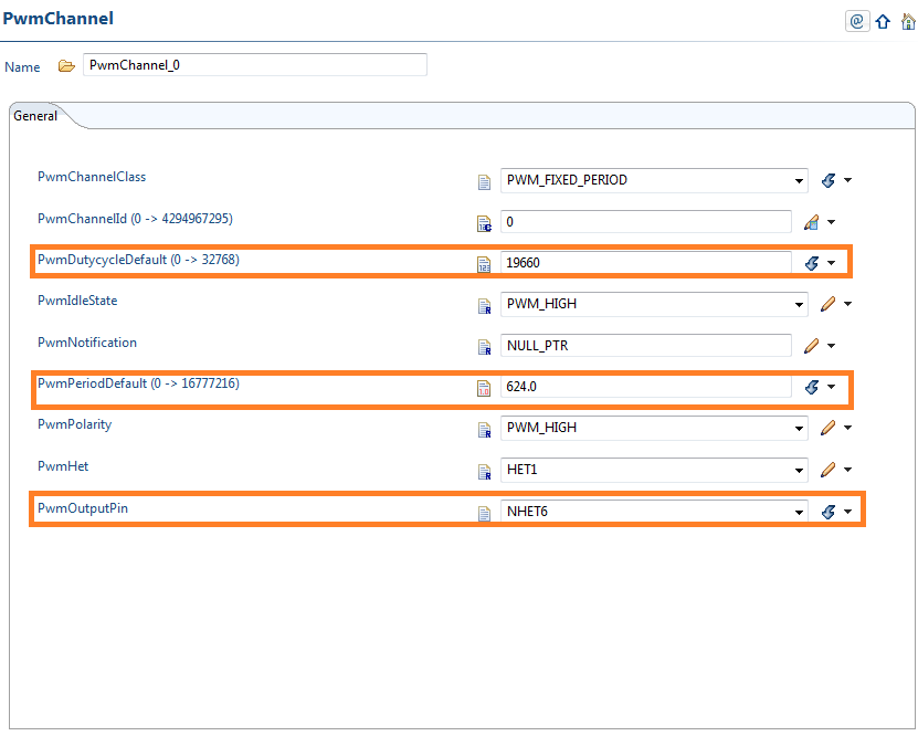
Inside the PwmChannel_0 configuration, select the output pin as NHET6 and the Pwmhet as HET1. The PwmPeriodDefault parameter has to be calculated from loop resolution period (LRP).
PwmPeriodDefault = (Signal Period/LRP) - 1
LRP = (hr * lr)/VCLK2
Ex: If VCLK2 is 80MHz, hr =1, lr =128 and signal period needed = 1ms,
LRP = (1 * 128)/80MHz = 1.6us
PwmPeriodDefault = (1ms/1.6us) – 1 = 624
The PwmDutyCycleDefault value is calculated as below,
PwmDutyCycleDefault = (DutyCycle% * 0X8000) or (DutyCycle% * 32768)
In our example, for 60% dutycycle, the value is 19660
2.3 Application
In this application, we are generating a PWM waveform on the NHET1_6 pin with 1ms period and 60% dutycycle as configured in the Eb tool.
#include  "Mcu.h"
#include  "Port.h"
#include  "Pwm.h"

int  main  (void)
{
  Mcu_Init(&McuModuleConfiguration_0);
  Port_Init(&Port_Runtime);
  Pwm_Init(&PwmChannelConfigSet_0);
  while (1){
  }

  return 0;
}
SPI
3.1 Introduction
The TMS570LS12xx has configurable serial peripheral interface (SPI). This document gives a head start into developing an SPI application using TI’s MCAL. It provides the necessary steps on how to configure the module in Eb tresos tool and then write an application to send/receive data through the SPI peripheral.
In this note, we are using TMS570LS1224 microcontroller’s SPI peripheral.
3.2 Configuration in Eb tresos tool
3.2.1 MCU
MCU module should be properly configured for the microcontroller before using any other module.
3.2.2 PORT
The PORT module does two things.
3.2.2.1 Functionality selection
SPI pins can be used for SPI functionality or General purpose input/output also. The selection of pins for SPI functionality has to be done here in the PORT module. For all the pins, proper direction also should be selected.
We will configure SPI1 for the TMS570LS1224 microcontroller.

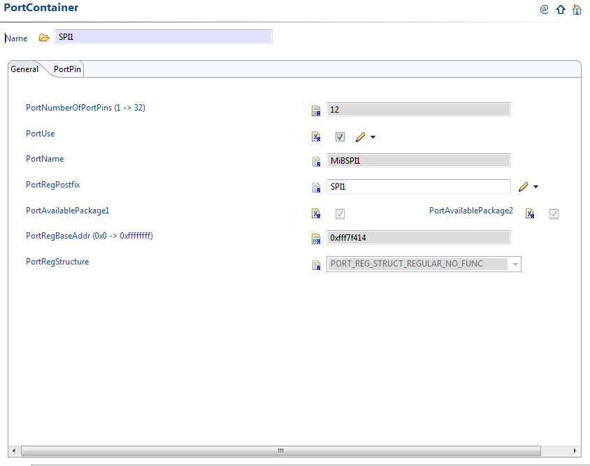
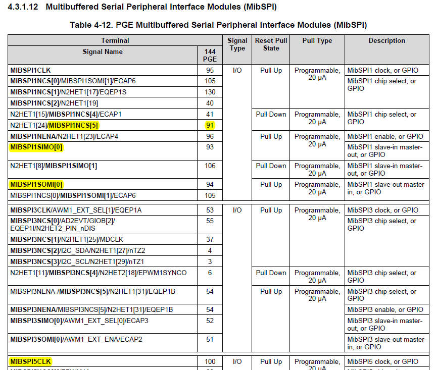
The Multi-buffered Serial peripheral interface (MiBSPI) of TMS570LS1224 has 12 pins which can be used for SPI or GIO.
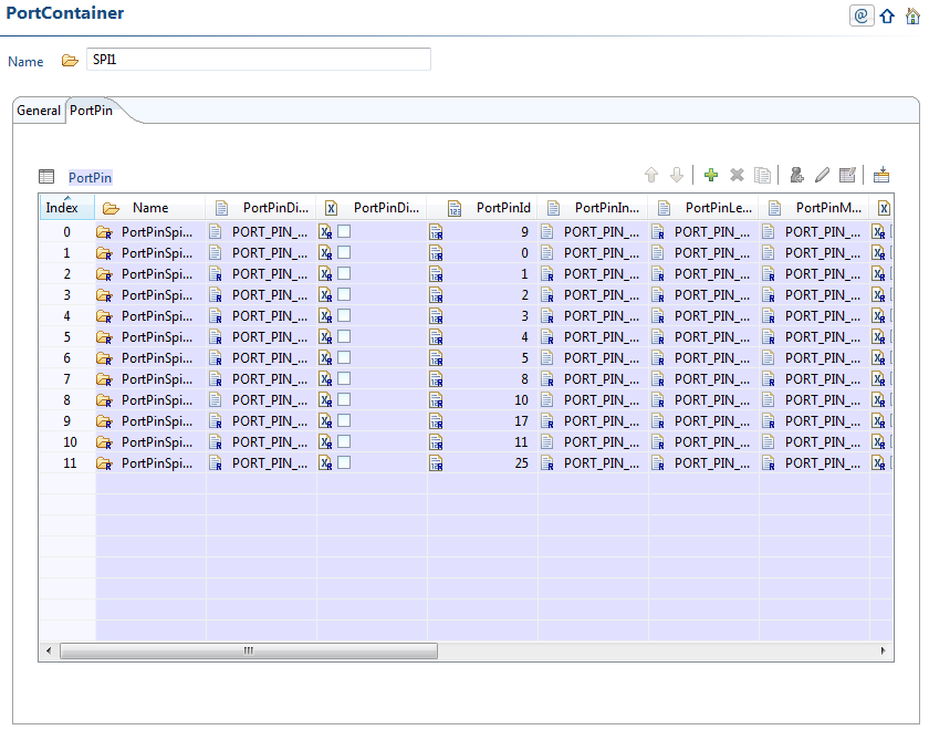

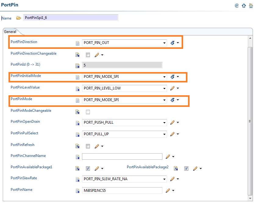
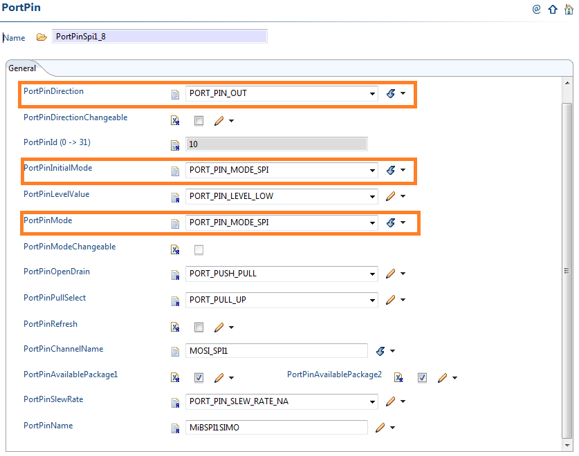
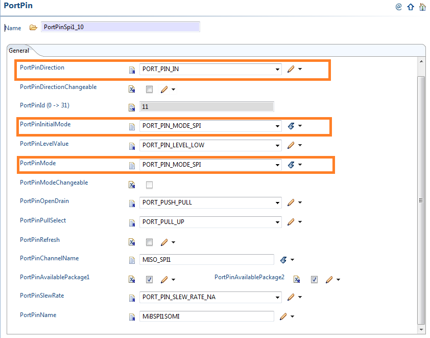
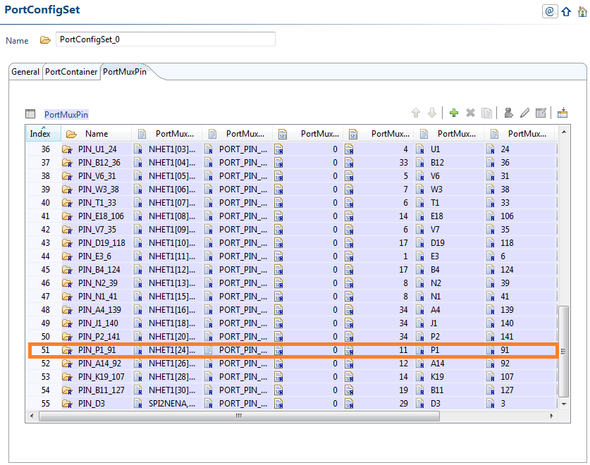
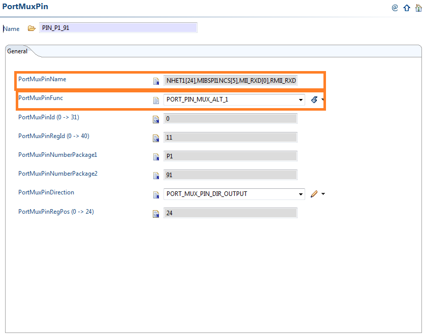
3.2.2.2 Pin Muxing
The SPI pins used for this application are SPICLK, SPISOMI, SPISIMO and SPINCS5. Refer the datasheet of TMS570LS1224. As we can see below, out of these four pins, three pins are of default functionality. Only SPINCS5 has to be selected in alternate functionality mode. (Make sure that the pins you select here are the same pins which are brought out in your board)
3.2.3 SPI
The AUTOSAR standard specifies a hierarchical structure of sequences, jobs and channels for the SPI module. We have to configure all of them to transmit/receive SPI data.
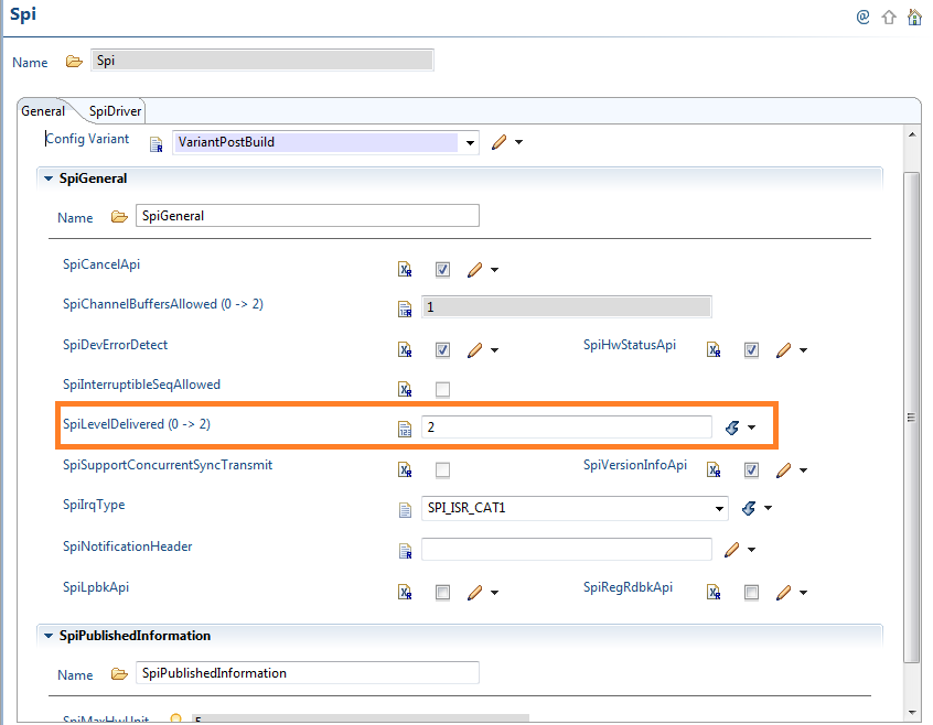
‘SpiLevelDelivered’ parameter gives the SPI Handler/Driver level of scalable functionality: SYNC ONLY(0), ASYNC ONLY(1), SYNC/ASYNC (2). We are selecting a value of 2 to support both SYNC and ASYNC transmit APIs in the driver source code.
In the example given, we are using SPI SYNC transmit API to transfer the data.

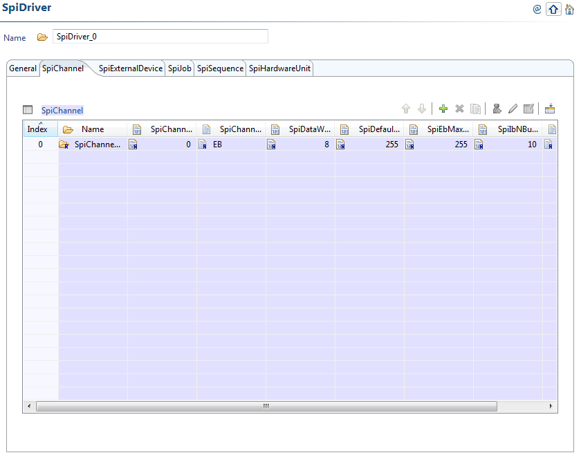
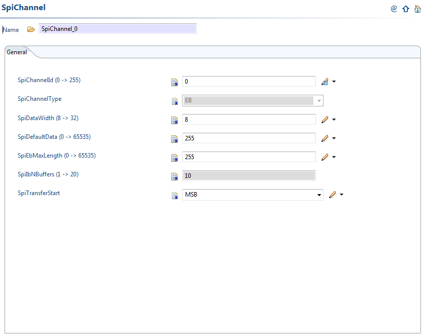
The data specific settings like data width, MSB/LSB first are selected in the SpiChannel_0 as shown below.
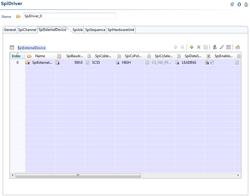
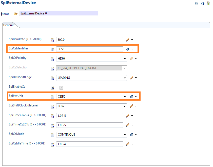
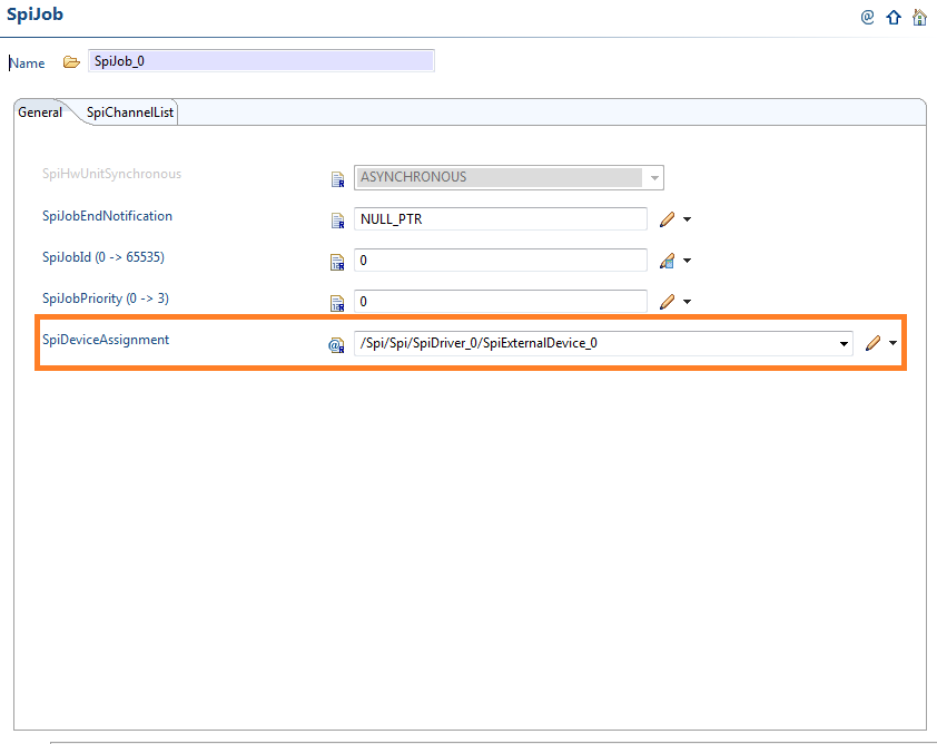
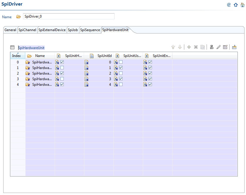
The external device specific settings like the chip select line used to communicate with the device, hardware unit used are configured in the below section. In our example, we are using SPINCS5 for the chip select and MibSPI1 (CSIB0) hardware unit.
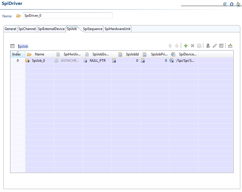
A job is a collection of channels with the same CS. Assign the external device to the job as shown below.
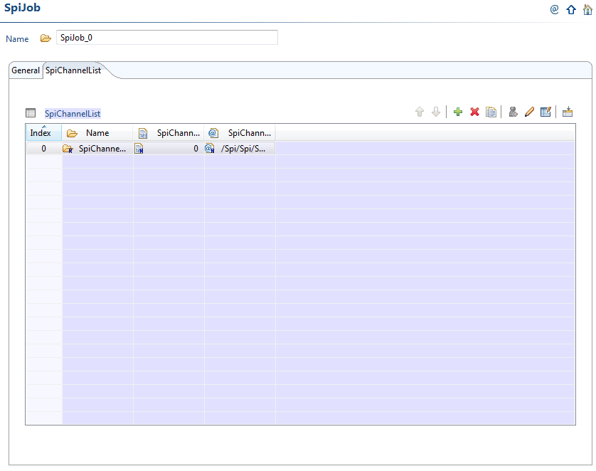
Include the channels to be used in this job.
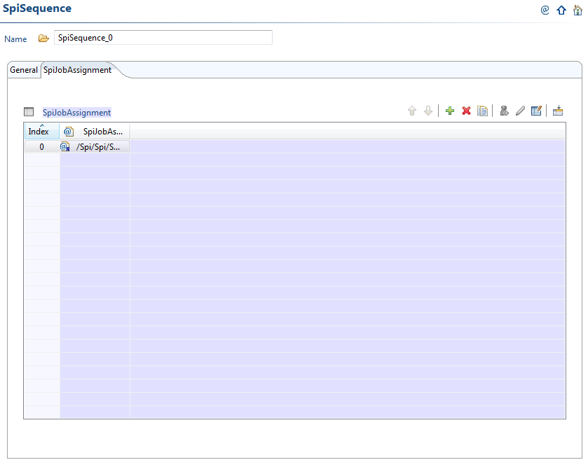
A sequence is a collection of jobs. When we transmit data in the application, a sequence is transmitted every time we call sync/async transmit API.
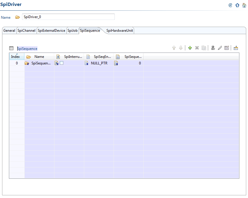
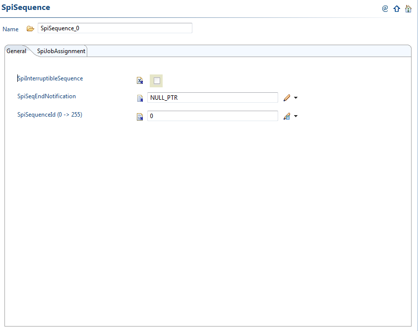
Assign the job we have configured previously to the sequence as shown below.
3.3 Application
In this example code, we are sending ten bytes through the SPI SIMO pin. We have connected the SIMO to SOMI and tested this application. The destination buffer will receive the values sent through the source buffer.
#include "Mcu.h"
#include "Port.h"
#include "Pwm.h"
#include "Spi.h"
#include "stdint.h"

uint8_t SrcBuff[10] = {1,2,3,4,5,6,7,8,9,'A'};
uint8_t DestBuff[10] = {0};

int main(void)
{
    Mcu_Init(&McuModuleConfiguration_0);
    Port_Init(&Port_Runtime);
    Spi_Init(&SpiRuntime);
    Spi_SetupEB(Spi_SpiChannel_0, SrcBuff, DestBuff, 10);
    Spi_SyncTransmit(Spi_SpiSequence_0);
    while (1){
    }
    return 0;
}
ADC
3.1 Introduction
The Texas Instruments Hercules safety microcontrollers TMS570LS12xx have configurable Analog to Digital converter (ADC) module. This document gives an example application to use the ADC module of TI MCAL for TMS570LSxx series of microcontrollers. It also gives all the necessary steps to configure the module in Eb tresos tool.
In this note, we are using TMS570LS1224 microcontroller’s ADC peripheral. This application uses two channels ADC1_5 and ADC1_6 in single shot mode which are software triggered.
3.2 Configuration in Eb tresos tool
3.2.1 MCU
MCU module should be properly configured for the microcontroller before using any other module.
3.2.2 PORT
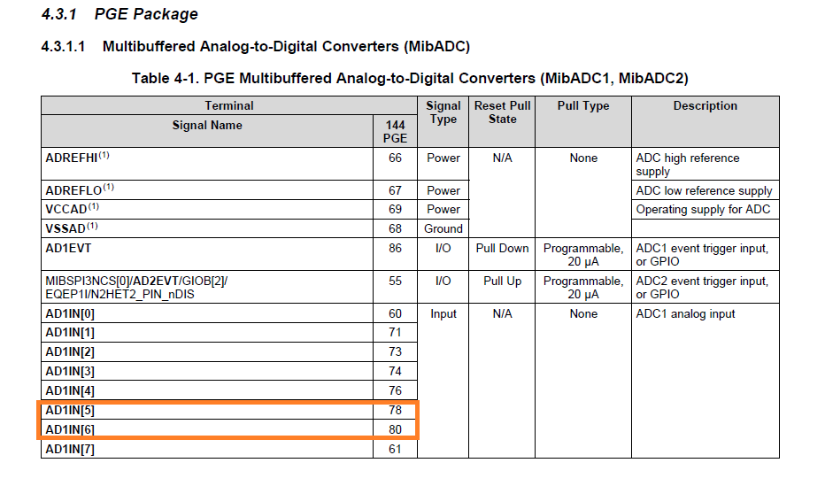
There is no need to configure functionality for the ADC pins unless we use them for GIO purpose. So, only pin muxing need to be taken care in PORT configuration. As we can see from the datasheet, there is no other functionality associated with these pins (AD1IN[5] and AD1IN[6]). So, we are not configuring anything in pin muxing part of PORT.
We will configure ADC for the TMS570LS1224 microcontroller.
3.2.3 ADC
The AUTOSAR standard specifies a configuration set containing ADC groups which in turn contain the ADC channels. There are three ADC groups which will convert all the channels assigned to them when we trigger the conversion.

The ADCHWFifo parameter which is used to calculate the number of groupends(samples) in the driver. It should be greater than the largest number of channels used in any group. ( For ex: If Ev group has 4, Group1 has 10, Group2 has 14 channels configured, then this value should be greater than or equal to 14). It should be less than or equal to the number of buffers assigned for the smallest group. (For ex: Refer Adc-cfg.h file, if Ev group has 20 buffers, Group1 has 20 buffers and Group2 has 24 buffers, it should be less than or equal to 20)
In our example, we have two channels in our group and the number of HW buffers for the group is 20. So, we are not changing the default value of 14.

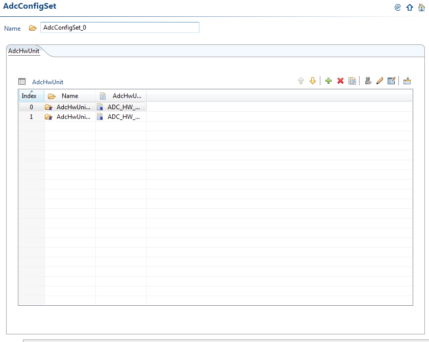
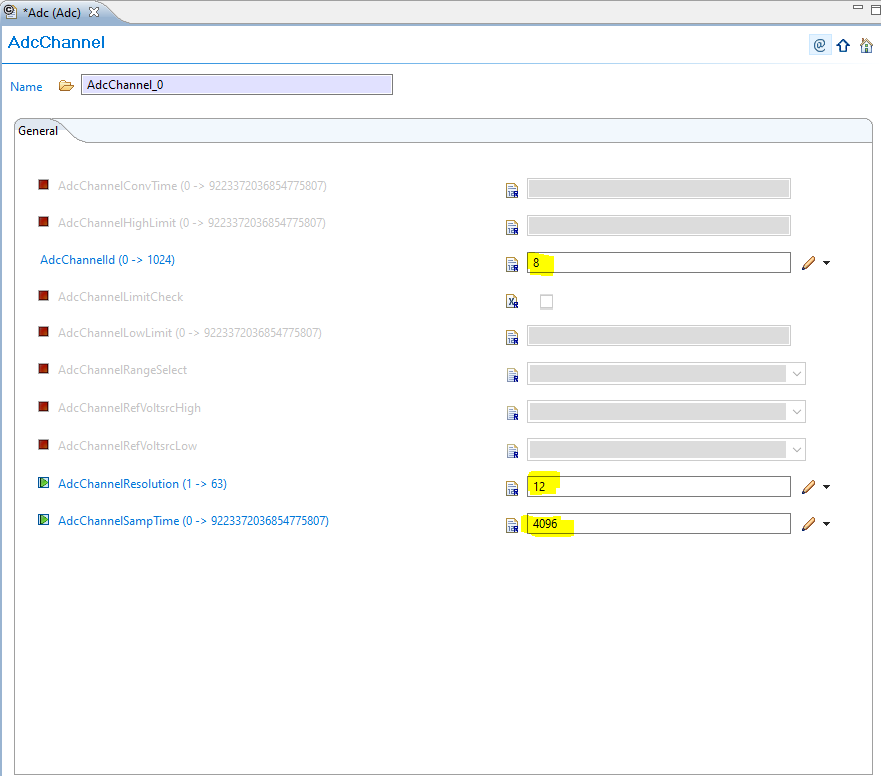
Select the ADC HwUnit 0 in this step. Go to Adc channel and change the channel id to 8, channel resolution to 12.
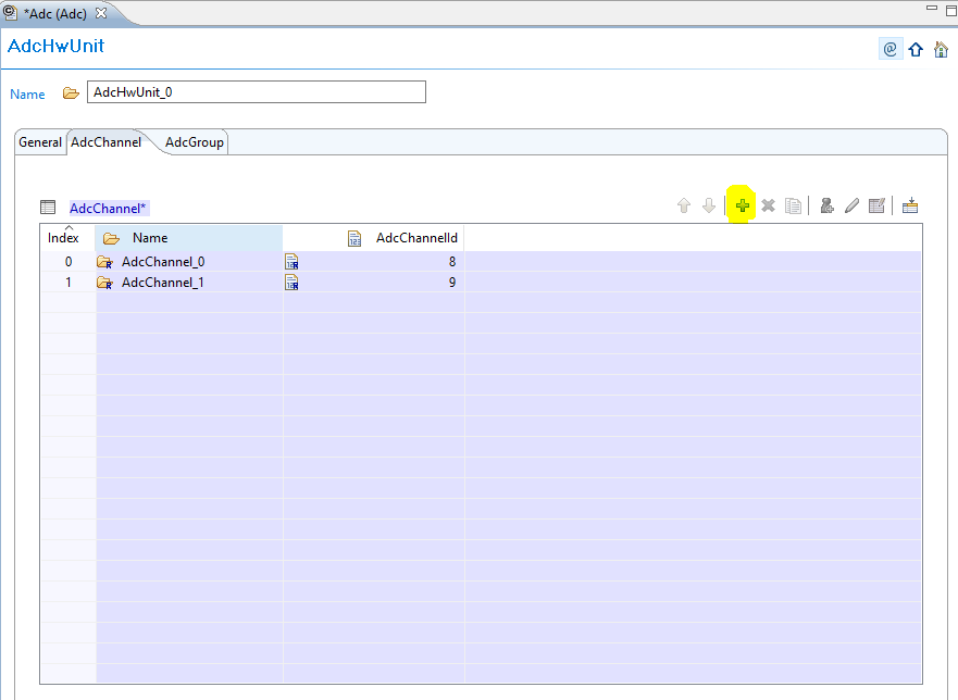
Click on the next channel and configure the channel id as 9.

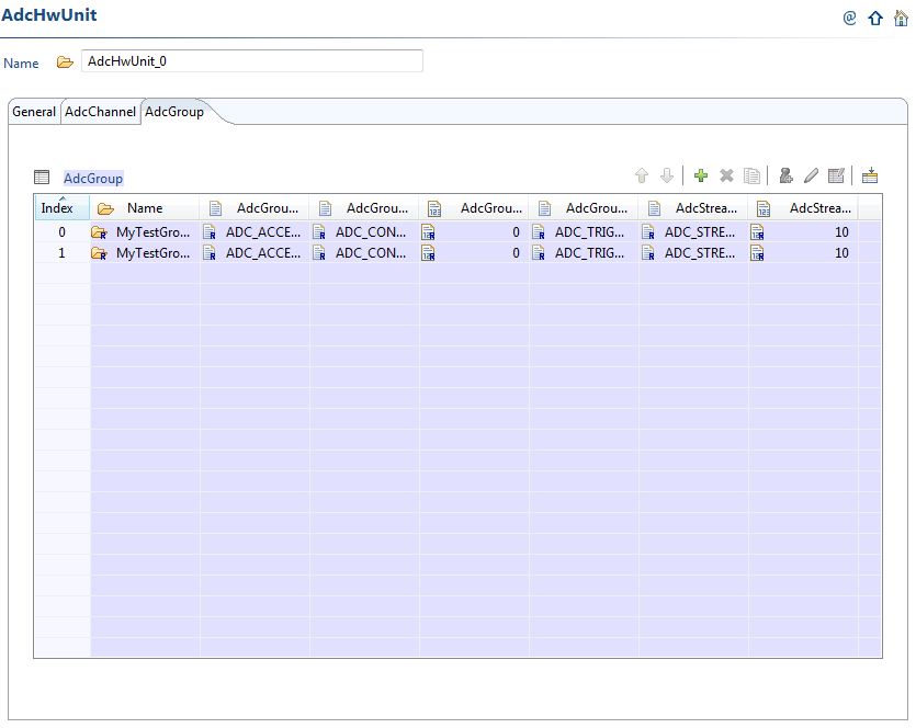
Go to the Group specific settings. We are configuring the first option (MyTestGroup1).
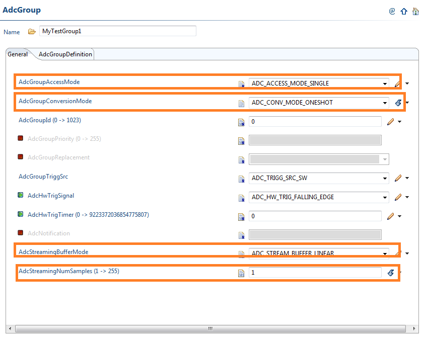
We are using the module in one shot mode and the buffer access mode is single. Select all the settings as shown.
Now, link the two channels to the group (MyTestGroup1 in our example).
3.3 Application
In the below example, we can find the results in the Adc_result_buffer1 after execution of
Adc_ReadGroup API.
#include "Mcu.h"
#include "Port.h"
#include "Adc.h"

Adc_ValueGroupRefType AdcDataBuffer;
Adc_ValueGroupType  Adc_result_buffer[40];
Adc_ValueGroupType  Adc_result_buffer1[40];

int i = 0;
int ret = 0;

int main(void)
{
    Mcu_Init(&McuModuleConfiguration_0);
    Port_Init(&Port_Runtime);
    Adc_Init(&AdcConfigSet_0);
    Adc_SetupResultBuffer(MyTestGroup1,(Adc_ValueGroupRefType)Adc_result_buffer);
    Adc_StartGroupConversion(MyTestGroup1);

    while(1){
       while (!(Adc_GetGroupStatus(MyTestGroup1) == ADC_STREAM_COMPLETED));
       ret = Adc_ReadGroup(MyTestGroup1,(Adc_ValueGroupRefType)&Adc_result_buffer1[0] ); //
       Adc_StopGroupConversion(MyTestGroup1);
       Adc_StartGroupConversion(MyTestGroup1);
    }
    return 0;
}
4.7. Frequently Asked Questions (FAQ)
How to find the version of AUTOSAR that works with a given version of MCAL Please check the release notes of the MCAL release to check for compatible AUTOSAR version. Latest MCAL 5.40 supports AUTOSAR 4.0.3.
Where can users find performance data for MCAL APIs? The memory footprint and performance of the MCAL APIs is published as part of the AUTOSAR MCAL package. Locate the file DataSheet_<DEVICE>_<VERSION>.pdf file in the root directory of the MCAL release.
Are there some modules not supported in TI MCAL? Yes, there are some modules like I2C, Ethernet and USB that are not supported in TI MCAL.
4.9. Technical Support
For technical support please post your questions and comments at http://e2e.ti.com

|
For technical support please post your questions on the Hercules safety microcontrollers forum of the TI E2E™ Support Forums. |