8.1. Loading
A program needs to be placed into the target device’s memory before it may be executed. Loading is the process of preparing a program for execution by initializing device memory with the program’s code and data. A loader might be another program on the device, an external agent (for example, a debugger), or the device might initialize itself after power-on, which is known as bootstrap loading, or bootloading.
The loader is responsible for constructing the load image in memory before the program starts. The load image is the program’s code and data in memory before execution. What exactly constitutes loading depends on the environment, such as whether an operating system is present. This section describes several loading schemes for bare-metal devices. This section is not exhaustive.
A program may be loaded in the following ways:
A debugger running on a connected host workstation. In a typical embedded development setup, the device is subordinate to a host running a debugger such as Code Composer Studio (CCS). The device is connected with a communication channel such as a JTAG interface. CCS reads the program and writes the load image directly to target memory through the communications interface.
“Burning” the load image onto an EPROM module.The hex converter (tiarmhex) can assist with this by converting the executable object file into a format suitable for input to an EPROM programmer. The EPROM is placed onto the device itself and becomes a part of the device’s memory. See Hex Conversion Utility Description for details.
Bootstrap loading from a dedicated peripheral, such as an I2C peripheral. The device may require a small program called a bootloader to perform the loading from the peripheral. The hex converter can assist in creating a bootloader.
Another program running on the device. The running program can create the load image and transfer control to the loaded program. If an operating system is present, it may have the ability to load and run programs.
8.1.1. Load and Run Addresses
Consider an embedded device for which the program’s load image is burned onto EPROM/ROM. Variable data in the program must be writable, and so must be located in writable memory, typically RAM. However, RAM is volatile, meaning it will lose its contents when the power goes out. If this data must have an initial value, that initial value must be stored somewhere else in the load image, or it would be lost when power is cycled. The initial value must be copied from the non-volatile ROM to its run-time location in RAM before it is used. See Using Linker-Generated Copy Tables for ways this is done.
The load address is the location of an object in the load image.
The run address is the location of the object as it exists during program execution.
An object is a chunk of memory. It represents a section, segment, function, or data.
The load and run addresses for an object may be the same. This is commonly the case for program code and read-only data, such as the .const section. In this case, the program can read the data directly from the load address. Sections that have no initial value, such as the .bss section, do not have load data and are considered to have load and run addresses that are the same. If you specify different load and run addresses for an uninitialized section, the linker provides a warning and ignores the load address.
The load and run addresses for an object may be different. This is commonly the case for writable data, such as the .data section. The .data section’s starting contents are placed in ROM and copied to RAM. This often occurs during program startup, but depending on the needs of the object, it may be deferred to sometime later in the program as described in Run-Time Relocation.
Symbols in assembly code and object files almost always refer to the run address. When you look at an address in the program, you are almost always looking at the run address. The load address is rarely used for anything but initialization.
The load and run addresses for a section are controlled by the linker command file and are recorded in the object file metadata.
The load address determines where a loader places the raw data for the section. Any references to the section (such as references to labels in it) refer to its run address. The application must copy the section from its load address to its run address before the first reference of the symbol is encountered at run time; this does not happen automatically simply because you specify a separate run address. For examples that specify load and run addresses, see Specifying Load and Run Addresses.
For an example that illustrates how to move a block of code at run time, see the example in Referring to the Load Address by Using the .label Directive. To create a symbol that lets you refer to the load-time address, rather than the run-time address, see the Referring to the Load Address by Using the .label Directive. To use copy tables to copy objects from load-space to run-space at boot time, see Using Linker-Generated Copy Tables.
ELF format executable object files contain segments. See Introduction to Sections for information about sections and segments.
8.1.2. Bootstrap Loading
The details of bootstrap loading (bootloading) vary a great deal between devices. Not every device supports every bootloading mode, and using the bootloader is optional. This section discusses various bootloading schemes to help you understand how they work. Refer to your device’s data sheet to see which bootloading schemes are available and how to use them.
A typical embedded system uses bootloading to initialize the device. The program code and data may be stored in ROM or FLASH memory. At power-on, an on-chip bootloader (the primary bootloader) built into the device hardware starts automatically.
Figure: Bootloading Sequence (Simplified)
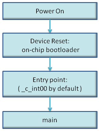
The primary bootloader is typically very small and copies a limited amount of memory from a dedicated location in ROM to a dedicated location in RAM. (Some bootloaders support copying the program from an I/O peripheral.) After the copy is completed, it transfers control to the program.
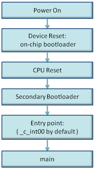
For many programs, the primary bootloader is not capable of loading the entire program, so these programs supply a more capable secondary bootloader. The primary bootloader loads the secondary bootloader and transfers control to it. Then, the secondary bootloader loads the rest of the program and transfers control to it. There can be any number of layers of bootloaders, each loading a more capable bootloader to which it transfers control.
Figure: Bootloading Sequence with Secondary Bootloader
8.1.2.1. Boot, Load, and Run Addresses
The boot address of a bootloaded object is where its raw data exists in ROM before power-on.
The boot, load, and run addresses for an object may all be the same; this is commonly the case for .const data. If they are different, the object’s contents must be copied to the correct location before the object may be used.
The boot address may be different than the load address. The bootloader is responsible for copying the raw data to the load address.
The boot address is not controlled by the linker command file or recorded in the object file; it is strictly a convention shared by the bootloader and the program.
8.1.2.2. Primary Bootloader
The detailed operation of the primary bootloader is device-specific. Some devices have complex capabilities such as booting from an I/O peripheral or configuring memory controller parameters.
8.1.2.3. Secondary Bootloader
The hex converter assumes the secondary bootloader is of a particular format. The hex converter’s model bootloader uses a boot table. You can use whatever format you want, but if you follow this model, the hex converter can create the boot table automatically.
8.1.2.4. Boot Table
The input for the model secondary bootloader is the boot table. The boot table contains records that instruct the secondary bootloader to copy blocks of data contained in the table to specified destination addresses. The hex conversion utility automatically builds the boot table for the secondary bootloader. Using the utility, you specify the sections you want to initialize, the boot table location, and the name of the section containing the secondary bootloader routine and where it should be located. The hex conversion utility builds a complete image of the table and adds it to the program.
The boot table is target-specific. For C6000, the format of the boot table is simple. A header record contains a 4-byte field that indicates where the boot loader should branch after it has completed copying data. After the header, each section that is to be included in the boot table has the following contents:
4-byte field containing the size of the section
4-byte field containing the destination address for the copy
the raw data
0 to 3 bytes of trailing padding to make the next field aligned to 4 bytes
More than one section can be entered; a termination block containing an all-zero 4-byte field follows the last section.
See The Boot Table Format for details about the boot table format.
8.1.2.5. Bootloader Routine
The bootloader routine is a normal function, except that it executes before the C environment is set up. For this reason, it can’t use the C stack, and it can’t call any functions that have yet to be loaded!
The following sample code is for C6000 and is from Creating a Second-Level Bootloader for FLASH Bootloading on TMS320C6000 Platform With Code Composer Studio (SPRA999).
Example: Sample Secondary Bootloader Routine
;  ======== boot_c671x.s62 ========

; global EMIF symbols defined for the c671x family
            .include        boot_c671x.h62
            .sect ".boot_load"
            .global _boot

_boot:
;************************************************************************
;* DEBUG LOOP − COMMENT OUT B FOR NORMAL OPERATION
;************************************************************************
zero B1
_myloop: ;  [!B1] B _myloop
            nop  5
_myloopend: nop
;************************************************************************
;* CONFIGURE EMIF
;************************************************************************
        ;****************************************************************
        ; *EMIF_GCTL = EMIF_GCTL_V;
        ;****************************************************************
            mvkl  EMIF_GCTL,A4
      ||    mvkl  EMIF_GCTL_V,B4
            mvkh  EMIF_GCTL,A4
      ||    mvkh  EMIF_GCTL_V,B4
            stw   B4,*A4
        ;****************************************************************
        ; *EMIF_CE0 = EMIF_CE0_V
        ;****************************************************************
            mvkl  EMIF_CE0,A4
      ||    mvkl  EMIF_CE0_V,B4
            mvkh  EMIF_CE0,A4
      ||    mvkh  EMIF_CE0_V,B4
            stw   B4,*A4
        ;****************************************************************
        ; *EMIF_CE1 = EMIF_CE1_V (setup for 8−bit async)
        ;****************************************************************
            mvkl  EMIF_CE1,A4
      ||    mvkl  EMIF_CE1_V,B4
            mvkh  EMIF_CE1,A4
      ||    mvkh  EMIF_CE1_V,B4
            stw   B4,*A4
        ;****************************************************************
        ; *EMIF_CE2 = EMIF_CE2_V (setup for 32−bit async)
        ;****************************************************************
            mvkl  EMIF_CE2,A4
      ||    mvkl  EMIF_CE2_V,B4
            mvkh  EMIF_CE2,A4
      ||    mvkh  EMIF_CE2_V,B4
            stw   B4,*A4
        ;****************************************************************
        ; *EMIF_CE3 = EMIF_CE3_V (setup for 32−bit async)
        ;****************************************************************
      ||    mvkl  EMIF_CE3,A4
      ||    mvkl  EMIF_CE3_V,B4      ;
            mvkh  EMIF_CE3,A4
      ||    mvkh  EMIF_CE3_V,B4
            stw   B4,*A4
        ;****************************************************************
        ; *EMIF_SDRAMCTL = EMIF_SDRAMCTL_V
        ;****************************************************************
      ||    mvkl  EMIF_SDRAMCTL,A4
      ||    mvkl  EMIF_SDRAMCTL_V,B4      ;
            mvkh  EMIF_SDRAMCTL,A4
      ||    mvkh  EMIF_SDRAMCTL_V,B4
            stw   B4,*A4
        ;****************************************************************
        ; *EMIF_SDRAMTIM = EMIF_SDRAMTIM_V
        ;****************************************************************
      ||    mvkl  EMIF_SDRAMTIM,A4
      ||    mvkl  EMIF_SDRAMTIM_V,B4      ;
            mvkh  EMIF_SDRAMTIM,A4
      ||    mvkh  EMIF_SDRAMTIM_V,B4
            stw   B4,*A4
        ;****************************************************************
        ; *EMIF_SDRAMEXT = EMIF_SDRAMEXT_V
        ;****************************************************************
      ||    mvkl  EMIF_SDRAMEXT,A4
      ||    mvkl  EMIF_SDRAMEXT_V,B4      ;
            mvkh  EMIF_SDRAMEXT,A4
      ||    mvkh  EMIF_SDRAMEXT_V,B4
            stw   B4,*A4
;****************************************************************************
; copy sections
;****************************************************************************
            mvkl  COPY_TABLE, a3 ; load table pointer
            mvkh  COPY_TABLE, a3
            ldw   *a3++, b1      ; Load entry point
copy_section_top:
            ldw   *a3++, b0      ; byte count
            ldw   *a3++, a4      ; ram start address
            nop   3
[!b0]       b copy_done          ; have we copied all sections?
            nop   5
copy_loop:
            ldb   *a3++,b5
            sub   b0,1,b0        ; decrement counter
[ b0]       b     copy_loop      ; setup branch if not done
[!b0]       b     copy_section_top
            zero  a1
[!b0]       and   3,a3,a1
            stb   b5,*a4++
[!b0]       and   −4,a3,a5       ; round address up to next multiple of 4
[ a1]       add   4,a5,a3        ; round address up to next multiple of 4
;****************************************************************************
; jump to entry point
;****************************************************************************
copy_done:
            b    .S2 b1
            nop  5