4.10. CDD ADC Module
4.10.1. Acronyms and Definitions
Abbreviation/Term |
Explanation |
|---|---|
AUTOSAR |
Automotive Open System Architecture |
ADC |
Analog to Digital Conversion |
API |
Application Programming Interface |
BSW |
Basic Software |
ECU |
Electronic Control Unit |
DET |
Default Error Tracer |
HW |
Hardware |
SW |
Software |
I/O |
Input/Output |
MCAL |
Micro Controller Abstraction Layer |
CDD |
Complex Device Driver |
OS |
Operating System |
RTE |
Runtime Environment |
SOC |
Start of Conversion |
EOC |
End of Conversion |
S&H |
Sample and Hold |
SAR |
Successive-Approximation-Register |
SYSCLK |
System Clock |
HW Unit |
Represents a microcontroller input electronic device that includes all parts necessary to perform an “analogue to digital conversion” |
ADC channel |
Represents a logical ADC entity bound to one port pin. Multiple ADC entities can be mapped to the same port pin |
ADC channel group |
A group of ADC channels linked to the same ADC hardware unit (e.g., one Sample & Hold and one A/D converter).The conversion of the whole group is triggered by one trigger source. |
ADC result buffer |
The user of the ADC Driver has to provide a buffer for every group. This buffer can hold multiple samples of the same channel group if streaming access mode is selected. If single access mode is selected one sample of each group channel is held in the buffer. |
Trigger Source |
Source event that starts a single conversion or a continuous series of conversions. |
Conversion Mode |
One-Shot:The conversion of an ADC channel group is performed once after a trigger and the result is written to the assigned buffer.A trigger can be a software API call or a hardware event. |
Sampling Time |
Time during which the analogue value is sampled (e.g. loading the capacitor, …) |
Conversion Time |
Time during which the sampled analogue value is converted into digital representation |
Acquisition Time |
Acquisition Time = Sampling Time+ Conversion Time |
GPT |
General Purpose Timer |
4.10.2. Introduction
The ADC driver is a part of complex device drivers (CDD) which converts the analog input to digital. It provides services to start and stop a group conversion respectively to enable and disable the trigger source for a conversion. Furthermore, it provides services to enable and disable a notification mechanism and routines to query the status and result of the group conversions.
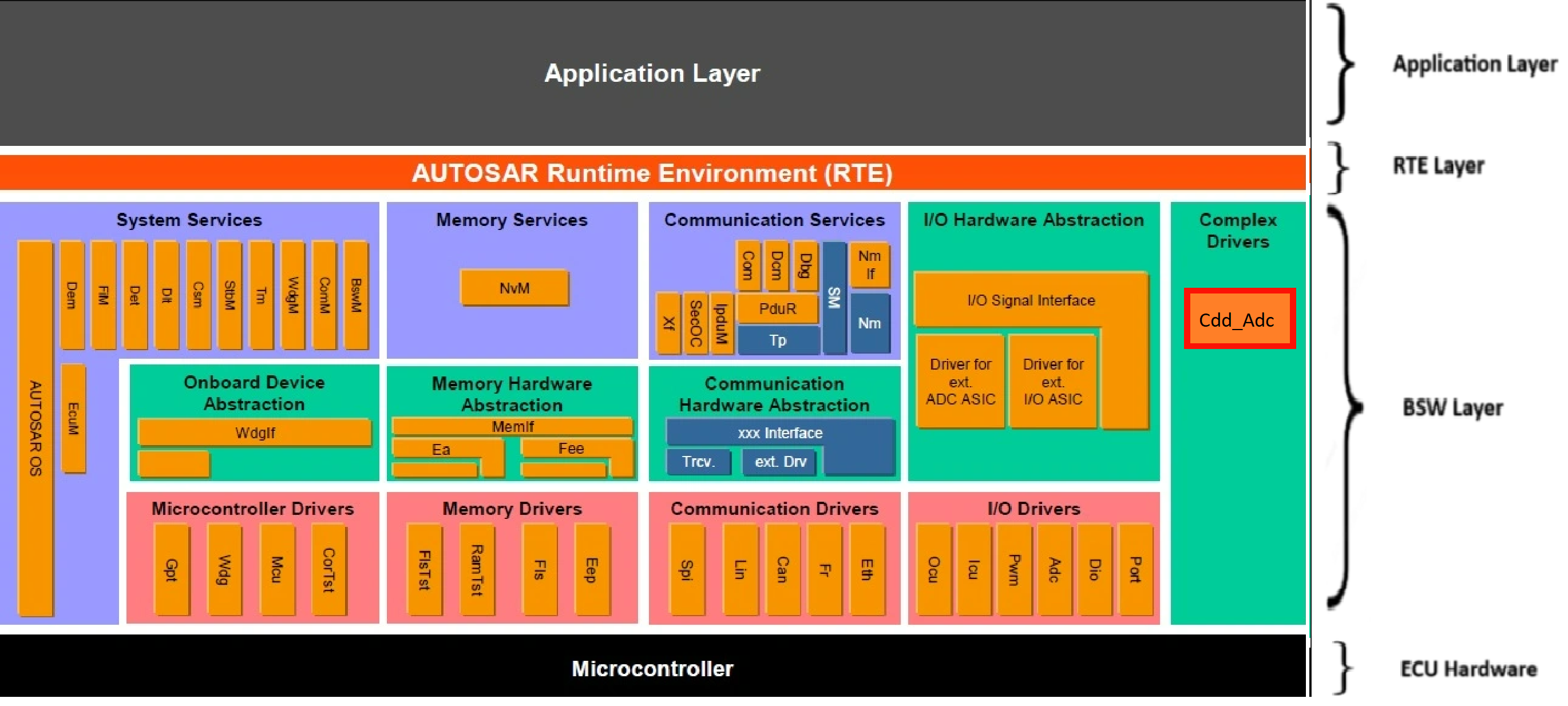
Fig. 4.37 CDD_ADC MCAL AUTOSAR
This document details AUTOSAR BSW CDD_ADC module implementation
Supported AUTOSAR Release |
4.3.1 |
|---|---|
Supported Configuration Variants |
Pre-Compile |
Vendor ID |
CDD_ADC_VENDOR_ID (44) |
Module ID |
CDD_ADC_MODULE_ID (255) |
4.10.3. Functional Overview
The ADC peripheral initializes and controls the internal Analogue Digital Converter Unit(s) of the microcontroller. The ADC peripheral in the device is Successive Approximation (SAR) type of ADC . The ADC peripherals on this device support selectable resolution of either 16 bit or 12 bit.The ADC is composed of a core and a wrapper; the core is composed of the analog circuits which include the channel select MUX, the Sample-and-Hold (S/H) circuit, the successive approximation circuits, voltage reference circuits, and other analog support circuits. The wrapper is composed of the digital circuits that configure and control the ADC. These circuits include the logic for programmable conversions, result registers, interfaces to analog circuits, interfaces to the peripheral buses,post-processing circuits, and interfaces to other on-chip peripherals.
4.10.4. Hardware Features
4.10.4.1. Hardware Features supported
The ADC module includes the following features:
Selectable resolution of 12 bits or 16 bits.
Ratiometric external reference set by VREFHI and VREFLO pins.
Selectable internal reference of 2.5V or 3.3V.
Differential signal conversions and Single-ended signal conversions.
Input multiplexer with up to 80 channels (single-ended) or 40 channels (differential).
External channel mux option to expand available ADC channels.
32 configurable SOCs.
32 individually addressable result registers.
Two trigger repeater modules, enabling customizable hardware oversampling and undersampling modes with little or no CPU overhead.
Multiple trigger sources -
S/W (with available global synchronization for multiple ADCs) - software immediate start
All ePWMs - ADCSOC A or B
GPIO XINT2
CPU Timers 0/1/2 (from each C29 core present)
ADCINT1/2
ECAP events in capture mode (CEVT1, CEVT2, CEVT3, and CEVT4) and APWM mode (period match, compare match, or both)
Four flexible PIPE interrupts
Configurable interrupt placement
Four post-processing blocks(PPB), each with:
Saturating offset calibration
Error from set-point calculation
High, low, and zero-crossing compare, with interrupt and ePWM trip capability
Trigger-to-sample delay capture
Aggregation functions: max, min, sum, and average (binary shift)
Configurable digital filter for high/low/zero-crossing compare
Absolute value function
Delta enable function
Two’s complement function
Cycle by cycle enable function
Result safety checkers to compare SOC results on same ADC or multiple ADC instances
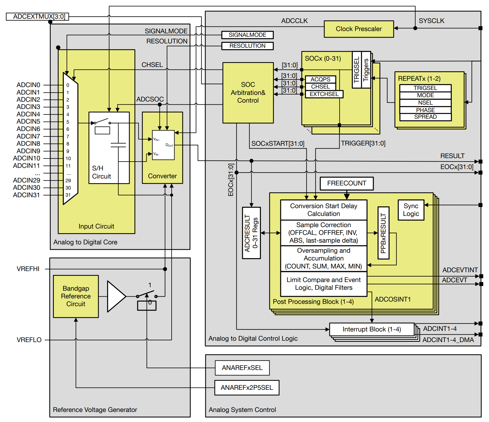
Fig. 4.38 Cdd_Adc Block Diagram
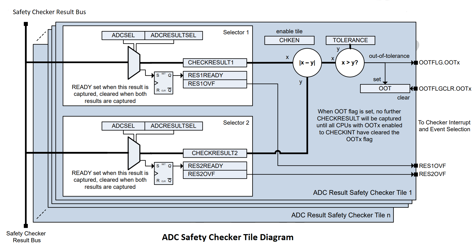
Fig. 4.39 Cdd_Adc Result Safety Checker Block Diagram
4.10.4.2. Features not supported by Hardware
The 1.65V internal reference mode is not supported when the ADC is configured for 16-bit resolution.
Temperature sensor sampled in 16-bit mode. It can cause incorrect ADC results.To sample the temperature sensor, the ADC must be in single-ended 12-bit mode.
4.10.4.3. Features Not supported by the driver
Burst mode
PPB external hardware sync input
PPB oversampling interrupt
4.10.4.4. Non compliance
None
4.10.5. Source files
📦f29h85x_mcal
┣ 📂build
┣ 📂docs
┣ 📂drivers
┃ ┣ 📂BSW_Stubs
┃ ┣ 📂Can
┃ ┣ 📂Cdd_Adc
┃ ┃ ┣ 📂include
┃ ┃ ┃ ┣ 📜Cdd_Adc.h : Contains the API declarations of the Cdd_Adc driver to be used by upper layers.
┃ ┃ ┃ ┣ 📜Cdd_Adc_Priv.h : Contains data structures and Internal function declarations.
┃ ┃ ┣ 📂src
┃ ┃ ┃ ┣ 📜Cdd_Adc.c : Contains the implementation of the API for Cdd_Adc driver.
┃ ┃ ┃ ┣ 📜Cdd_Adc_Irq.c : Contains the implementation for Cdd_Adc interrupts handlers.
┃ ┃ ┃ ┗ 📜Cdd_Adc_Priv.c : Contains Functions that support the API for Cdd_Adc driver
┃ ┃ ┗ 📜CMakeLists.txt
┃ ┣ 📂Cdd_Sent
┃ ┣ 📂Cdd_Xbar
┃ ┣ 📂Dio
┃ ┣ 📂Gpt
┃ ┣ 📂hw_include
┃ ┣ 📂Lin
┃ ┣ 📂Mcal_Lib
┃ ┣ 📂Mcu
┃ ┗ 📂Port
┃ ┗ 📂Spi
┃ ┗ 📂Wdg
┣ 📂examples
┣ 📂plugins
┣ 📜CMakeLists.txt
┗ 📜CMakePresets.json
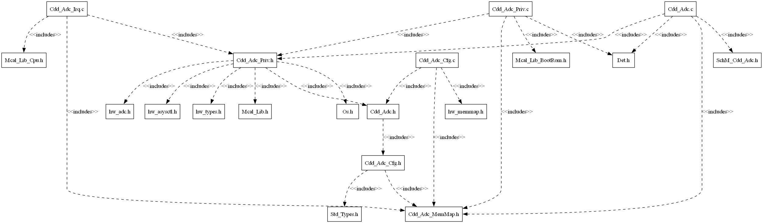
Fig. 4.40 Cdd_Adc Header File Structure
4.10.6. Module requirements
4.10.6.1. Memory Mapping
Will be added in later release
4.10.6.2. Scheduling
None
4.10.6.3. Error handling
Development errors are reported to the DET using the service Det_ReportError(), when enabled. The driver interface contains the MACRO declaration of the error codes to be returned.
4.10.6.4. Error codes
4.10.6.4.1. Development Errors
Type of Error |
Related Error code |
Value (Hex) |
|---|---|---|
Init API called when the driver is already initialized |
CDD_ADC_E_ALREADY_INITIALIZED |
0x0DU |
Init API called with non NULL_PTR |
CDD_ADC_E_PARAM_POINTER |
0x14U |
API called when driver is not initialized |
CDD_ADC_E_UNINIT |
0x0AU |
API called with invalid group ID |
CDD_ADC_E_PARAM_GROUP |
0x15U |
API called with invalid parameter ID |
CDD_ADC_E_INVALID_ID |
0x22U |
API called for group conversion before setting up the result buffer |
CDD_ADC_E_BUFFER_UNINIT |
0x1DU |
Cdd_Adc_EnableGroupNotification or Cdd_Adc_DisableGroupNotification API called for a group whose configuration set has no notification available |
CDD_ADC_E_NOTIF_CAPABILITY |
0x1CU |
Incorrect API call for group conversion |
CDD_ADC_E_WRONG_TRIGG_SRC |
0x1BU |
Cdd_Adc_EnableHardwareTrigger or Cdd_Adc_DisableHardwareTrigger API called on a group with conversion mode configured as continuous |
CDD_ADC_E_WRONG_CONV_MODE |
0x1AU |
Cdd_Adc_SetResolution API is called when the hardware is in Internal 3.3V reference mode or called on 12-bit ADC hardware units(ADCC,ADCD & ADCE) and 16bit resolution is requested |
CDD_ADC_E_WRONG_RESOLUTION_MODE |
0x18U |
API called for invalid configuration parameter |
CDD_ADC_E_PARAM_CONFIG |
0x0EU |
4.10.6.4.2. Runtime Errors
Type of Error |
Related Error code |
Value (Hex) |
|---|---|---|
Cdd_Adc_SetResolution API called on a hardware unit whose resolution is same as the requested resolution |
CDD_ADC_E_ALREADY_SET |
0x21U |
API called when group conversion is not on-going |
CDD_ADC_E_IDLE |
0x0CU |
API called during ongoing group conversion |
CDD_ADC_E_BUSY |
0x0BU |
API called when safety checker is IDLE |
CDD_ADC_E_CHECKER_IDLE |
0x1FU |
API called when safety checker is BUSY |
CDD_ADC_E_CHECKER_BUSY |
0x20U |
Cdd_Adc_GetDelayStamp API called for software triggered PPB |
CDD_ADC_E_WRONG_TRIGG_SRC |
0x1BU |
4.10.7. Used resources
4.10.7.1. Interrupt Handling
Cdd_Adc driver provides ISRs. The ISRs are implemented in the Cdd_Adc_Irq.c file. Interrupt and the category should be selected in the Cdd_Adc plugin.The Interrupt ID associated with the ADC instance is mentioned in the TRM (also, please refer the Example application).
Cdd_Adc Instance |
Interrupt handler |
|---|---|
ADCA |
Cdd_Adc_ADCA_Int1Isr |
ADCA |
Cdd_Adc_ADCA_Int2Isr |
ADCA |
Cdd_Adc_ADCA_Int3Isr |
ADCA |
Cdd_Adc_ADCA_Int4Isr |
ADCA |
Cdd_Adc_ADCA_PpbEvtIntIsr |
ADCB |
Cdd_Adc_ADCB_Int1Isr |
ADCB |
Cdd_Adc_ADCB_Int2Isr |
ADCB |
Cdd_Adc_ADCB_Int3Isr |
ADCB |
Cdd_Adc_ADCB_Int4Isr |
ADCB |
Cdd_Adc_ADCB_PpbEvtIntIsr |
ADCC |
Cdd_Adc_ADCC_Int1Isr |
ADCC |
Cdd_Adc_ADCC_Int2Isr |
ADCC |
Cdd_Adc_ADCC_Int3Isr |
ADCC |
Cdd_Adc_ADCC_Int4Isr |
ADCC |
Cdd_Adc_ADCC_PpbEvtIntIsr |
ADCD |
Cdd_Adc_ADCD_Int1Isr |
ADCD |
Cdd_Adc_ADCD_Int2Isr |
ADCD |
Cdd_Adc_ADCD_Int3Isr |
ADCD |
Cdd_Adc_ADCD_Int4Isr |
ADCD |
Cdd_Adc_ADCE_PpbEvtIntIsr |
ADCE |
Cdd_Adc_ADCE_Int1Isr |
ADCE |
Cdd_Adc_ADCE_Int2Isr |
ADCE |
Cdd_Adc_ADCE_Int3Isr |
ADCE |
Cdd_Adc_ADCE_Int4Isr |
ADCE |
Cdd_Adc_ADCE_PpbEvtIntIsr |
Note
Same Interrupt Category needs to be configured in both Cdd_Adc and OS Module. Since all the PPBs in an ADC hardware share the same interrupt, the category must match for all the PPB containers under an ADC hardware unit container.
4.10.7.2. Instance support
CPU instances |
supported |
|---|---|
CPU 1 |
YES |
CPU 2 |
NO |
CPU 3 |
NO |
4.10.7.3. Hardware-Software Mapping
Below image shows Cdd_Adc driver Hardware-Software mapping. For more information related to HW/SW mapping, refer the F29x Technical Reference Manual.
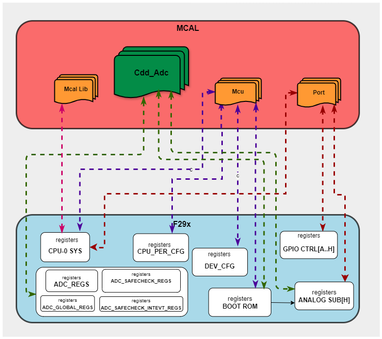
Fig. 4.41 Cdd_Adc HW/SW Mapping
4.10.8. Integration description
4.10.8.1. Dependent modules
4.10.8.1.1. DET
This driver depends on the DET in order to report development and runtime errors. The detection of development errors is configurable ON/OFF. The switch CDD_ADC_DEV_ERROR_DETECT will activate or deactivate the detection of development errors. Runtime errors are reported even when CDD_ADC_DEV_ERROR_DETECT is OFF.
4.10.8.1.2. SchM
If multiple AUTOSAR runnables have access to the same Data Store Memory block, the exported AUTOSAR specification enforces data consistency by using an AUTOSAR exclusive area. With this specification, the runnables have mutually exclusive access to the per-instance memory global data, which prevents data corruption. Beside the OS, the BSW Scheduler provides functions that CDD ADC module calls at begin and end of critical sections. This implementation requires 1 level of exclusive access to guard critical sections.
The data consistency mechanism that has to be applied to an ExclusiveArea might be domain, ECU or even project specific. The decision which mechanism has to be applied by RTE / Basic Software Scheduler is taken during ECU integration by setting the Exclusive Area configuration parameter RteExclusiveAreaImplMechanism. This parameter is an input for RTE generator.
For CDD_ADC Module, data consistency and exclusive access to critical sections are required for the following sections as shown in the table below:
Exclusive Area Functions used |
CDD_ADC Function calling Exclusive Area |
Need for Exclusive Area |
Recommended Exclusive Area Mapping |
|---|---|---|---|
CDD_ADC_EXCLUSIVE_AREA_0 |
Cdd_Adc_StartGroupConversion |
To protect against multiple access for shared resources |
OS_RESOURCE : If the CDD ADC APIs are only called from pre-emptible task context, its recommended to use this mechanism as it takes care of resource access protection and task priority management. |
4.10.8.1.3. MCU
MCU Module is required for the ADC clock initialization.
4.10.8.1.4. Port
The Port module configures the analog port pins used for the ADC driver. Hence, the Port driver has to be initialized prior to use ADC functions and to observe proper conversion results. Otherwise incorrect conversion results will be observed.
4.10.8.1.5. OS
The Cdd_Adc driver uses interrupts and therefore depends on OS, which configures the interrupts.
4.10.8.2. Multi-core and Resource allocator
Not Supported
4.10.9. Configuration
The Cdd_Adc Driver implementation supports only Pre-Compile configuration variant. The driver needs the generated configuration header file Cdd_Adc_Cfg.h as an input file to work. The generated configuration source file Cdd_Adc_Cfg.c is also necessary for the driver configuration.
The generated configuration files should not be modified manually. The config tool Elektrobit Tresos should be used to modify the configuration files. If edited manually the driver may behavior might deviate from the expected behavior.
4.10.9.1. Migration Guide to v2.0.0 from v1.0.0
To make v1.0.0 Adc schema(generated .xdm file) compatible with v2.0.0 below changes are required:
Change ‘AR-ELEMENT’ name from Cdd_Adc to Cdd.
Update MODULE-CONFIGURATION path from ‘ASPath:/TI_F29H85x/Cdd_Adc’ to ‘ASPath:/TI_F29H85x/Cdd_Adc/Cdd’.
REFERENCE type parameters refers to other parameter by it’s schema path. With the schema change in the plugin(.xdm file) the schema path has also changed which requires manual update for the already existing configuration.
For example: CddAdcPpbChannel expects reference to a channel. With old schema the path was ‘/Cdd_Adc/Cdd_Adc/CddAdcConfigSet/CddAdcHwUnit_0/CddAdcGroup_0/CddAdcChannel_0’, this should be updated to ‘/Cdd_Adc/Cdd/CddAdcConfigSet/CddAdcHwUnit_0/CddAdcGroup_0/CddAdcChannel_0’ to fit with the latest schema.
Earlier schema:
<d:lst type="TOP-LEVEL-PACKAGES">
<d:ctr name="Cdd_Adc" type="AR-PACKAGE">
<d:lst type="ELEMENTS">
<d:chc name="Cdd_Adc" type="AR-ELEMENT" value="MODULE-CONFIGURATION">
<d:ctr type="MODULE-CONFIGURATION">
<a:a name="DEF" value="ASPath:/TI_F29H85x/Cdd_Adc"/>

Modified new schema:
<d:lst type="TOP-LEVEL-PACKAGES">
<d:ctr name="Cdd_Adc" type="AR-PACKAGE">
<d:lst type="ELEMENTS">
<d:chc name="Cdd" type="AR-ELEMENT" value="MODULE-CONFIGURATION">
<d:ctr type="MODULE-CONFIGURATION">
<a:a name="DEF" value="ASPath:/TI_F29H85x/Cdd_Adc/Cdd"/>
4.10.9.2. CddAdcConfigSet
This container contains the configuration parameters and sub containers of the Cdd Adc module.
4.10.9.2.1. CddAdcEnableTemperatureSensor
Item |
|
|---|---|
Name |
CddAdcEnableTemperatureSensor |
Description |
Enables/Disables the temperature sensor. |
Origin |
Texas Instruments |
Post-Build-Variant-Value |
false |
Value-Configuration-Class |
– |
Pre-Compile-Time |
VARIANT-PRE-COMPILE |
Default-value |
false |
4.10.9.2.2. CddAdcLockTemperatureSensor
Item |
|
|---|---|
Name |
CddAdcLockTemperatureSensor |
Description |
Locks the temperature sensor configuration register When enabled .This is editable only when the temperature sensor is enabled. |
Origin |
Texas Instruments |
Post-Build-Variant-Value |
false |
Value-Configuration-Class |
– |
Pre-Compile-Time |
VARIANT-PRE-COMPILE |
Default-value |
false |
4.10.9.2.3. CddAdcInternalTestInput
Item |
|
|---|---|
Name |
CddAdcInternalTestInput |
Description |
Selects the input source for the internal test nodes for the ADC hardware unit. |
Origin |
Texas Instruments |
Post-Build-Variant-Value |
false |
Value-Configuration-Class |
– |
Pre-Compile-Time |
VARIANT-PRE-COMPILE |
Default-value |
CDD_ADC_TEST_NODE_NO_CONN |
Range |
CDD_ADC_TEST_NODE_NO_CONN |
4.10.9.2.4. CddAdcHwUnitAnalogRefABVoltageMode
Item |
|
|---|---|
Name |
CddAdcHwUnitAnalogRefABVoltageMode |
Description |
This parameter defines the voltage reference mode for ADC A and B hardware instances. |
Origin |
Texas Instruments |
Post-Build-Variant-Value |
false |
Value-Configuration-Class |
– |
Pre-Compile-Time |
VARIANT-PRE-COMPILE |
Default-value |
CDD_ADC_REFERENCE_INTERNAL |
Range |
CDD_ADC_REFERENCE_INTERNAL |
4.10.9.2.5. CddAdcHwUnitAnalogRefABVoltage
Item |
|
|---|---|
Name |
CddAdcHwUnitAnalogRefABVoltage |
Description |
This parameter defines the reference voltage for A and B instances of the ADC. This paramter is applicable only when the voltage reference mode is INTERNAL. |
Origin |
Texas Instruments |
Post-Build-Variant-Value |
false |
Value-Configuration-Class |
– |
Pre-Compile-Time |
VARIANT-PRE-COMPILE |
Default-value |
CDD_ADC_REFERENCE_2_5V |
Range |
CDD_ADC_REFERENCE_3_3V |
4.10.9.2.6. CddAdcHwUnitAnalogRefCDEVoltageMode
Item |
|
|---|---|
Name |
CddAdcHwUnitAnalogRefCDEVoltageMode |
Description |
This parameter defines the voltage reference mode for C,D and E instances of the ADC. |
Origin |
Texas Instruments |
Post-Build-Variant-Value |
false |
Value-Configuration-Class |
– |
Pre-Compile-Time |
VARIANT-PRE-COMPILE |
Default-value |
CDD_ADC_REFERENCE_INTERNAL |
Range |
CDD_ADC_REFERENCE_INTERNAL |
4.10.9.2.7. CddAdcHwUnitAnalogRefCDEVoltage
Item |
|
|---|---|
Name |
CddAdcHwUnitAnalogRefCDEVoltage |
Description |
This parameter defines the reference voltage for C,D and E instances of the ADC.This paramter is applicable only when the voltage reference mode is INTERNAL. |
Origin |
Texas Instruments |
Post-Build-Variant-Value |
false |
Value-Configuration-Class |
– |
Pre-Compile-Time |
VARIANT-PRE-COMPILE |
Default-value |
CDD_ADC_REFERENCE_3_3V |
Range |
CDD_ADC_REFERENCE_3_3V |
4.10.9.2.8. CddAdcHwUnit
This container contains the driver configuration (parameters) for the ADC Hardware Unit
4.10.9.2.8.1. CddAdcHwInstance
Item |
|
|---|---|
Name |
CddAdcHwInstance |
Description |
This parameter describes the ADC HW Unit instance. |
Origin |
Texas Instruments |
Post-Build-Variant-Value |
false |
Value-Configuration-Class |
– |
Pre-Compile-Time |
VARIANT-PRE-COMPILE |
Default-value |
CDD_ADCA |
Range |
CDD_ADCA |
4.10.9.2.8.2. CddAdcHwUnitId
Item |
|
|---|---|
Name |
CddAdcHwUnitId |
Description |
This parameter indicates harware unit index among all the configured hardware units. |
Origin |
Texas Instruments |
Post-Build-Variant-Value |
false |
Value-Configuration-Class |
– |
Pre-Compile-Time |
VARIANT-PRE-COMPILE |
Default-value |
0 |
Max-value |
4 |
Min-value |
0 |
4.10.9.2.8.3. CddAdcSocPriorityMode
Item |
|
|---|---|
Name |
CddAdcSocPriorityMode |
Description |
This parameter defines the SOC priority of the ADC hardware unit. If the selected priority is 0 then all SOCs are handled in round robin mode,for any other value channels with SOC number below the Priority value are handled in high priority mode and the rest of the SOCs will be handled in round robin mode. By default round robin mode is configured. |
Origin |
Texas Instruments |
Post-Build-Variant-Value |
false |
Value-Configuration-Class |
– |
Pre-Compile-Time |
VARIANT-PRE-COMPILE |
Default-value |
0 |
Max-value |
32 |
Min-value |
0 |
4.10.9.2.8.4. CddAdcHwUnitResolution
Item |
|
|---|---|
Name |
CddAdcHwUnitResolution |
Description |
This parameter defines the resolution of the hardware unit assigned to the group(in bits). |
Origin |
Texas Instruments |
Post-Build-Variant-Value |
false |
Value-Configuration-Class |
– |
Pre-Compile-Time |
VARIANT-PRE-COMPILE |
Default-value |
CDD_ADC_RESOLUTION_12BIT |
Range |
CDD_ADC_RESOLUTION_12BIT |
4.10.9.2.8.5. CddAdcHwUnitSignalMode
Item |
|
|---|---|
Name |
CddAdcHwUnitSignalMode |
Description |
This parameter defines the signal mode of the group.Differential mode is supported only for ADC instances A and B. |
Origin |
Texas Instruments |
Post-Build-Variant-Value |
false |
Value-Configuration-Class |
– |
Pre-Compile-Time |
VARIANT-PRE-COMPILE |
Default-value |
CDD_ADC_MODE_SINGLE_ENDED |
Range |
CDD_ADC_MODE_SINGLE_ENDED |
4.10.9.2.8.6. CddAdcHwUnitClockPrescale
Item |
|
|---|---|
Name |
CddAdcHwUnitClockPrescale |
Description |
This enum describes the clock prescale factor for the ADC Hardware unit. |
Origin |
Texas Instruments |
Post-Build-Variant-Value |
false |
Value-Configuration-Class |
– |
Pre-Compile-Time |
VARIANT-PRE-COMPILE |
Default-value |
CDD_ADC_CLK_DIV_3_5 |
Range |
CDD_ADC_CLK_DIV_1_0 |
4.10.9.2.8.7. CddAdcClock
Item |
|
|---|---|
Name |
CddAdcClock |
Description |
This parameter describes the ADC clock after the clock prescale factor for the ADC Hardware unit. |
Origin |
Texas Instruments |
Post-Build-Variant-Value |
false |
Value-Configuration-Class |
– |
Pre-Compile-Time |
VARIANT-PRE-COMPILE |
Default-value |
5.0E7 |
Max-value |
6.0E7 |
Min-value |
5000000.0 |
4.10.9.2.8.8. CddAdcHwExternalMuxSelect
Item |
|
|---|---|
Name |
CddAdcHwExternalMuxSelect |
Description |
This parameter determines whether the external mux channel is enabled for the ADC hardware unit. |
Origin |
Texas Instruments |
Post-Build-Variant-Value |
false |
Value-Configuration-Class |
– |
Pre-Compile-Time |
VARIANT-PRE-COMPILE |
Default-value |
false |
4.10.9.2.8.9. CddAdcHwExternalMuxPreselectEnable
Item |
|
|---|---|
Name |
CddAdcHwExternalMuxPreselectEnable |
Description |
This parameter determines whether the external mux preset is enabled for the ADC hardware unit. |
Multiplicity-Configuration-Class |
– |
Pre-Compile Time |
VARIANT-PRE-COMPILE |
Origin |
Texas Instruments |
Post-build-variant-multiplicity |
false |
Post-Build-Variant-Value |
false |
Value-Configuration-Class |
– |
Pre-Compile-Time |
VARIANT-PRE-COMPILE |
Default-value |
false |
4.10.9.2.8.10. CddAdcInterruptPulseMode
Item |
|
|---|---|
Name |
CddAdcInterruptPulseMode |
Description |
This enumeration defines the interrupt pulse mode of the ADc hardware unit. |
Origin |
Texas Instruments |
Post-Build-Variant-Value |
false |
Value-Configuration-Class |
– |
Pre-Compile-Time |
VARIANT-PRE-COMPILE |
Default-value |
CDD_ADC_PULSE_END_OF_CONV |
Range |
CDD_ADC_PULSE_END_OF_ACQ_WIN |
4.10.9.2.8.11. CddAdcInterruptCycleoffset
Item |
|
|---|---|
Name |
CddAdcInterruptCycleoffset |
Description |
This parameter defines the delay from the fall edge of the SOC and the interrupt to be generated in SYSCLK cycles . |
Origin |
Texas Instruments |
Post-Build-Variant-Value |
false |
Value-Configuration-Class |
– |
Pre-Compile-Time |
VARIANT-PRE-COMPILE |
Default-value |
0 |
Max-value |
65535 |
Min-value |
0 |
4.10.9.2.8.12. CddAdcOpenShortDetectMode
Item |
|
|---|---|
Name |
CddAdcOpenShortDetectMode |
Description |
This parameter defines the opens/shorts detection circuit mode . |
Origin |
Texas Instruments |
Post-Build-Variant-Value |
false |
Value-Configuration-Class |
– |
Pre-Compile-Time |
VARIANT-PRE-COMPILE |
Default-value |
CDD_ADC_OSDETECT_MODE_DISABLED |
Range |
CDD_ADC_OSDETECT_MODE_DISABLED |
4.10.9.2.8.13. CddAdcClockReference
Item |
|
|---|---|
Name |
CddAdcClockReference |
Description |
Reference to a container of the type McuClockReferencePoint, to select an input clock. |
Origin |
Texas Instruments |
Post-Build-Variant-Value |
false |
Value-Configuration-Class |
– |
Pre-Compile-Time |
VARIANT-PRE-COMPILE |
4.10.9.2.9. CddAdcGroup
This container contains the Group configuration (parameters).
4.10.9.2.9.1. CddAdcGroupId
Item |
|
|---|---|
Name |
CddAdcGroupId |
Description |
Numeric ID of the group. This parameter is the symbolic name to be used on the API. This symbolic name allows accessing Channel Group data. This value will be assigned to the symbolic name derived of the CddAdcGroup container shortName. |
Origin |
Texas Instruments |
Post-Build-Variant-Value |
false |
Value-Configuration-Class |
– |
Pre-Compile-Time |
VARIANT-PRE-COMPILE |
Default-value |
0 |
Max-value |
3 |
Min-value |
0 |
4.10.9.2.9.2. CddAdcGroupPriority
Item |
|
|---|---|
Name |
CddAdcGroupPriority |
Description |
Priority of the group. |
Origin |
Texas Instruments |
Post-Build-Variant-Value |
false |
Value-Configuration-Class |
– |
Pre-Compile-Time |
VARIANT-PRE-COMPILE |
Default-value |
CDD_ADC_ROUND_ROBIN |
Range |
CDD_ADC_HIGH_PRIORITY |
4.10.9.2.9.3. CddAdcGroupSocMask
Item |
|
|---|---|
Name |
CddAdcGroupSocMask |
Description |
SOC mask of the Adc hardware unit of the group. |
Origin |
Texas Instruments |
Post-Build-Variant-Value |
false |
Value-Configuration-Class |
– |
Pre-Compile-Time |
VARIANT-PRE-COMPILE |
Default-value |
0 |
Max-value |
4294967295 |
Min-value |
0 |
4.10.9.2.9.4. CddAdcGroupConversionMode
Item |
|
|---|---|
Name |
CddAdcGroupConversionMode |
Description |
This parameter defines the type of conversion mode for the group. |
Origin |
Texas Instruments |
Post-Build-Variant-Value |
false |
Value-Configuration-Class |
– |
Pre-Compile-Time |
VARIANT-PRE-COMPILE |
Default-value |
CDD_ADC_CONV_MODE_ONESHOT |
Range |
CDD_ADC_CONV_MODE_CONTINUOUS |
4.10.9.2.9.5. CddAdcGroupTrigSrcType
Item |
|
|---|---|
Name |
CddAdcGroupTrigSrcType |
Description |
Type of source event that starts a group conversion. |
Origin |
Texas Instruments |
Post-Build-Variant-Value |
false |
Value-Configuration-Class |
– |
Pre-Compile-Time |
VARIANT-PRE-COMPILE |
Default-value |
CDD_ADC_TRIGG_SRC_SW |
Range |
CDD_ADC_TRIGG_SRC_HW |
4.10.9.2.9.6. CddAdcGroupTrigSrc
Item |
|
|---|---|
Name |
CddAdcGroupTrigSrc |
Description |
Source of the trigger that triggers the start of the conversion of all the channels in the group. |
Origin |
Texas Instruments |
Post-Build-Variant-Value |
false |
Value-Configuration-Class |
– |
Pre-Compile-Time |
VARIANT-PRE-COMPILE |
Default-value |
CDD_ADC_TRIGGER_SW_ONLY |
Range |
CDD_ADC_TRIGGER_SW_ONLY |
4.10.9.2.9.7. CddAdcGroupAccessMode
Item |
|
|---|---|
Name |
CddAdcGroupAccessMode |
Description |
This parameter defines the access mode of thegroup conversion results. |
Origin |
Texas Instruments |
Post-Build-Variant-Value |
false |
Value-Configuration-Class |
– |
Pre-Compile-Time |
VARIANT-PRE-COMPILE |
Default-value |
CDD_ADC_ACCESS_MODE_SINGLE |
Range |
CDD_ADC_ACCESS_MODE_SINGLE |
4.10.9.2.9.8. CddAdcGroupHwTrigSignal
Item |
|
|---|---|
Name |
CddAdcGroupHwTrigSignal |
Description |
Configures on which edge of the hardware trigger signal the driver should react, i.e. start the conversion (only if supported by the ADC hardware). |
Origin |
Texas Instruments |
Post-Build-Variant-Value |
false |
Value-Configuration-Class |
– |
Pre-Compile-Time |
VARIANT-PRE-COMPILE |
Default-value |
CDD_ADC_HW_TRIG_RISING_EDGE |
Range |
CDD_ADC_HW_TRIG_BOTH_EDGES |
4.10.9.2.9.9. CddAdcGroupStreamingBufferMode
Item |
|
|---|---|
Name |
CddAdcGroupStreamingBufferMode |
Description |
Configure streaming buffer as “linear buffer” (i.e. the ADC Driver stops the conversion as soon as the stream buffer is full) or as “ring buffer” (wraps around if the end of the stream buffer is reached). |
Origin |
Texas Instruments |
Post-Build-Variant-Value |
false |
Value-Configuration-Class |
– |
Pre-Compile-Time |
VARIANT-PRE-COMPILE |
Default-value |
CDD_ADC_STREAM_BUFFER_LINEAR |
Range |
CDD_ADC_STREAM_BUFFER_CIRCULAR |
4.10.9.2.9.10. CddAdcGroupStreamingNumSamples
Item |
|
|---|---|
Name |
CddAdcGroupStreamingNumSamples |
Description |
Number of ADC values to be acquired per channel in streaming access mode. |
Origin |
Texas Instruments |
Post-Build-Variant-Value |
false |
Value-Configuration-Class |
– |
Pre-Compile-Time |
VARIANT-PRE-COMPILE |
Default-value |
1 |
Max-value |
255 |
Min-value |
1 |
4.10.9.2.9.11. CddAdcInterruptCategory
Item |
|
|---|---|
Name |
CddAdcInterruptCategory |
Description |
This parameters defines the category of the interrupt. |
Origin |
Texas Instruments |
Post-Build-Variant-Value |
false |
Value-Configuration-Class |
– |
Pre-Compile-Time |
VARIANT-PRE-COMPILE |
Default-value |
ISR_CAT1_RTINT |
Range |
ISR_CAT1_INT |
4.10.9.2.9.12. CddAdcGroupNotification
Item |
|
|---|---|
Name |
CddAdcGroupNotification |
Description |
Callback function for each group |
Multiplicity-Configuration-Class |
– |
Pre-Compile Time |
VARIANT-PRE-COMPILE |
Origin |
Texas Instruments |
Post-build-variant-multiplicity |
false |
Post-Build-Variant-Value |
false |
Value-Configuration-Class |
– |
Pre-Compile-Time |
VARIANT-PRE-COMPILE |
Default-value |
NULL_PTR |
4.10.9.2.9.13. CddAdcInterruptSelect
Item |
|
|---|---|
Name |
CddAdcInterruptSelect |
Description |
This parameter defines to which interrupt the group is linked. |
Origin |
Texas Instruments |
Post-Build-Variant-Value |
false |
Value-Configuration-Class |
– |
Pre-Compile-Time |
VARIANT-PRE-COMPILE |
Default-value |
CDD_ADC_INT1 |
Range |
CDD_ADC_INT1 |
4.10.9.2.9.14. CddAdcInterruptSocSelect
Item |
|
|---|---|
Name |
CddAdcInterruptSocSelect |
Description |
This parameter allows interrupt as the trigger source of the group in addition to trigger select. This is applicable only for the interrupts CDD_ADC_INT1 and CDD_ADC_INT2. |
Origin |
Texas Instruments |
Post-Build-Variant-Value |
false |
Value-Configuration-Class |
– |
Pre-Compile-Time |
VARIANT-PRE-COMPILE |
Default-value |
CDD_ADC_INT_SOC_TRIGGER_NONE |
Range |
CDD_ADC_INT_SOC_TRIGGER_NONE |
4.10.9.2.9.15. CddAdcContinueToInterruptMode
Item |
|
|---|---|
Name |
CddAdcContinueToInterruptMode |
Description |
This parameters enables/disables the continue to interrupt mode for the specified interrupt. |
Origin |
Texas Instruments |
Post-Build-Variant-Value |
false |
Value-Configuration-Class |
– |
Pre-Compile-Time |
VARIANT-PRE-COMPILE |
Default-value |
false |
4.10.9.2.9.16. CddAdcTrigRepeaterReference
Item |
|
|---|---|
Name |
CddAdcTrigRepeaterReference |
Description |
Reference to the trigger repeater. |
Multiplicity-Configuration-Class |
– |
Pre-Compile Time |
VARIANT-PRE-COMPILE |
Origin |
Texas Instruments |
Post-build-variant-multiplicity |
false |
Post-Build-Variant-Value |
false |
Value-Configuration-Class |
– |
Pre-Compile-Time |
VARIANT-PRE-COMPILE |
4.10.9.2.10. CddAdcChannel
This container contains the channel configuration (parameters) depending on the hardware capability.
4.10.9.2.10.1. CddAdcChannelId
Item |
|
|---|---|
Name |
CddAdcChannelId |
Description |
This parameter defines to the numeric ID of the channel on the ADC hardware unit. Only some channels are brought out on the deive. Some of the channels are connected internally. So,while confguring the channel IDs make sure the channels have pin out on the deivce and are configured in Port. |
Origin |
Texas Instruments |
Post-Build-Variant-Value |
false |
Value-Configuration-Class |
– |
Pre-Compile-Time |
VARIANT-PRE-COMPILE |
Default-value |
0 |
Max-value |
31 |
Min-value |
0 |
4.10.9.2.10.2. CddAdcSocNumber
Item |
|
|---|---|
Name |
CddAdcSocNumber |
Description |
This parameter defines the assignment of the channel to the physical ADC hardware channel. |
Origin |
Texas Instruments |
Post-Build-Variant-Value |
false |
Value-Configuration-Class |
– |
Pre-Compile-Time |
VARIANT-PRE-COMPILE |
Default-value |
0 |
Max-value |
31 |
Min-value |
0 |
4.10.9.2.10.3. CddAdcSocExternalChannelSelect
Item |
|
|---|---|
Name |
CddAdcSocExternalChannelSelect |
Description |
This parameter defines the assignment of the external channel based on the digital output pins. |
Origin |
Texas Instruments |
Post-Build-Variant-Value |
false |
Value-Configuration-Class |
– |
Pre-Compile-Time |
VARIANT-PRE-COMPILE |
Default-value |
0 |
Max-value |
15 |
Min-value |
0 |
4.10.9.2.10.4. CddAdcChannelSampleWindow
Item |
|
|---|---|
Name |
CddAdcChannelSampleWindow |
Description |
Configuration of sampling time, i.e. the time during which the value is sampled, (in SYSCLK cycles) for each channel, if supported by hardware. Minimum value should be 15 to meet the minimum acquistsition window duration. |
Origin |
Texas Instruments |
Post-Build-Variant-Value |
false |
Value-Configuration-Class |
– |
Pre-Compile-Time |
VARIANT-PRE-COMPILE |
Default-value |
15 |
Max-value |
511 |
Min-value |
15 |
4.10.9.2.11. CddAdcTriggerRepeater
This container contains the trigger repeater configuration (parameters) depending on the hardware capability. To have this container enabled trigger source type should be hardware, trigger source should be one of the repeaters and trigger repeater should be enabled in the CddAdcGeneral container.
4.10.9.2.11.1. CddAdcRepeaterInstance
Item |
|
|---|---|
Name |
CddAdcRepeaterInstance |
Description |
Numeric ID of the trigger repeater instance. |
Origin |
Texas Instruments |
Post-Build-Variant-Value |
false |
Value-Configuration-Class |
– |
Pre-Compile-Time |
VARIANT-PRE-COMPILE |
Default-value |
0 |
Max-value |
1 |
Min-value |
0 |
4.10.9.2.11.2. CddAdcRepeaterTriggerSrc
Item |
|
|---|---|
Name |
CddAdcRepeaterTriggerSrc |
Description |
Trigger source of the trigger repeater. |
Origin |
Texas Instruments |
Post-Build-Variant-Value |
false |
Value-Configuration-Class |
– |
Pre-Compile-Time |
VARIANT-PRE-COMPILE |
Default-value |
CDD_ADC_TRIGGER_CPU1INT0 |
Range |
CDD_ADC_TRIGGER_CPU1INT0 |
4.10.9.2.11.3. CddAdcRepeaterMode
Item |
|
|---|---|
Name |
CddAdcRepeaterMode |
Description |
This parameter configures the trigger repeater mode. In oversampling mode (CddAdcTriggerCount+1) triggers are generated and in undersampling mode (CddAdcTriggerCount+1) triggers are suppressed. |
Origin |
Texas Instruments |
Post-Build-Variant-Value |
false |
Value-Configuration-Class |
– |
Pre-Compile-Time |
VARIANT-PRE-COMPILE |
Default-value |
OVERSAMPLING_MODE |
Range |
OVERSAMPLING_MODE |
4.10.9.2.11.4. CddAdcTriggerCount
Item |
|
|---|---|
Name |
CddAdcTriggerCount |
Description |
This parameter selects the number of triggers. When 0 is selected 1 trigger is generated (pass-through). |
Origin |
Texas Instruments |
Post-Build-Variant-Value |
false |
Value-Configuration-Class |
– |
Pre-Compile-Time |
VARIANT-PRE-COMPILE |
Default-value |
0 |
Max-value |
127 |
Min-value |
0 |
4.10.9.2.11.5. CddAdcTriggerPhaseDelay
Item |
|
|---|---|
Name |
CddAdcTriggerPhaseDelay |
Description |
This parameter defines the number of SYSCLKs to delay the selected trigger before passing it onto the re-triggering logic. |
Origin |
Texas Instruments |
Post-Build-Variant-Value |
false |
Value-Configuration-Class |
– |
Pre-Compile-Time |
VARIANT-PRE-COMPILE |
Default-value |
0 |
Max-value |
65535 |
Min-value |
0 |
4.10.9.2.11.6. CddAdcTriggerSpreadDelay
Item |
|
|---|---|
Name |
CddAdcTriggerSpreadDelay |
Description |
This parameter defines the minimum number of SYSCLKs to wait before creating the next repeated trigger to the ADC. This parameter has no effect in undersampling mode or when the TriggerCount is set to 0 |
Origin |
Texas Instruments |
Post-Build-Variant-Value |
false |
Value-Configuration-Class |
– |
Pre-Compile-Time |
VARIANT-PRE-COMPILE |
Default-value |
0 |
Max-value |
65535 |
Min-value |
0 |
4.10.9.2.12. CddAdcPpbConfig
This container contains the PPB configuration (parameters) of the PPB.
4.10.9.2.12.1. CddAdcPpbId
Item |
|
|---|---|
Name |
CddAdcPpbId |
Description |
Numeric ID of the PPB number assigned to the channel. |
Origin |
Texas Instruments |
Post-Build-Variant-Value |
false |
Value-Configuration-Class |
– |
Pre-Compile-Time |
VARIANT-PRE-COMPILE |
Default-value |
0 |
Max-value |
3 |
Min-value |
0 |
4.10.9.2.12.2. CddAdcPpbSocNumber
Item |
|
|---|---|
Name |
CddAdcPpbSocNumber |
Description |
Soc number of the selected channel. This is a calculated value, it can’t be edited. |
Origin |
Texas Instruments |
Post-Build-Variant-Value |
false |
Value-Configuration-Class |
– |
Pre-Compile-Time |
VARIANT-PRE-COMPILE |
Default-value |
0 |
Max-value |
31 |
Min-value |
0 |
4.10.9.2.12.3. CddAdcPpbCalibrationOffset
Item |
|
|---|---|
Name |
CddAdcPpbCalibrationOffset |
Description |
This parameters configures the offset calibration for the ADC channel.For values from 0 to 511,the configured value will be subtracted from the PPB result. For values from 512,(1024 - CddAdcPpbCalibrationOffset) value will be added to the PPB result. In case multiple PPBs point to the same SOC, only the OFFCAL of the lowest PPB ID will be applied. This offset value will be subtracted from the raw conversion result and stores the value in the ADC result register. The addition/subtraction satureated at o on the low ed and either 4095/65536 on the high end for 12-bit and 16-bit respectively. |
Origin |
Texas Instruments |
Post-Build-Variant-Value |
false |
Value-Configuration-Class |
– |
Pre-Compile-Time |
VARIANT-PRE-COMPILE |
Default-value |
0 |
Max-value |
1024 |
Min-value |
0 |
4.10.9.2.12.4. CddAdcPpbReferenceOffset
Item |
|
|---|---|
Name |
CddAdcPpbReferenceOffset |
Description |
This parameters configures the reference offset value for the ADC channel.In 12-bit mode the reference offset shouldn’t exceed 4095 in 12-bit and 65535 in 16-bit mode. |
Origin |
Texas Instruments |
Post-Build-Variant-Value |
false |
Value-Configuration-Class |
– |
Pre-Compile-Time |
VARIANT-PRE-COMPILE |
Default-value |
0 |
Max-value |
65535 |
Min-value |
0 |
4.10.9.2.12.5. CddAdcPpbDeltaEnable
Item |
|
|---|---|
Name |
CddAdcPpbDeltaEnable |
Description |
This parameters configures the bit to enable/disable delta enable. |
Origin |
Texas Instruments |
Post-Build-Variant-Value |
false |
Value-Configuration-Class |
– |
Pre-Compile-Time |
VARIANT-PRE-COMPILE |
Default-value |
false |
4.10.9.2.12.6. CddAdcPpbEnableTwosComplement
Item |
|
|---|---|
Name |
CddAdcPpbEnableTwosComplement |
Description |
This parameters configures the bit to enable/disable two’s complement. |
Origin |
Texas Instruments |
Post-Build-Variant-Value |
false |
Value-Configuration-Class |
– |
Pre-Compile-Time |
VARIANT-PRE-COMPILE |
Default-value |
false |
4.10.9.2.12.7. CddAdcPpbAbsoluteEnable
Item |
|
|---|---|
Name |
CddAdcPpbAbsoluteEnable |
Description |
This parameters configures the bit to enable/disable absolute value calculation. This is done before the two’s complement logic, so enabling both CddAdcPpbEnableTwosComplement and CddAdcPpbAbsoluteEnable will always result in a negative PPB value. |
Origin |
Texas Instruments |
Post-Build-Variant-Value |
false |
Value-Configuration-Class |
– |
Pre-Compile-Time |
VARIANT-PRE-COMPILE |
Default-value |
false |
4.10.9.2.12.8. CddAdcPpbCyclebyCycleEnable
Item |
|
|---|---|
Name |
CddAdcPpbCyclebyCycleEnable |
Description |
This parameters configures the bit to enable/disable cycle by cycle enable. |
Origin |
Texas Instruments |
Post-Build-Variant-Value |
false |
Value-Configuration-Class |
– |
Pre-Compile-Time |
VARIANT-PRE-COMPILE |
Default-value |
false |
4.10.9.2.12.9. CddAdcPpbCompareSource
Item |
|
|---|---|
Name |
CddAdcPpbCompareSource |
Description |
This parameters configures the PPB result type used for the zero-crossing detect logic and threshold compare. |
Origin |
Texas Instruments |
Post-Build-Variant-Value |
false |
Value-Configuration-Class |
– |
Pre-Compile-Time |
VARIANT-PRE-COMPILE |
Default-value |
CDD_ADC_COMPARE_PPBRESULT |
Range |
CDD_ADC_COMPARE_PPBRESULT |
4.10.9.2.12.10. CddAdcPpbTripHighLimit
Item |
|
|---|---|
Name |
CddAdcPpbTripHighLimit |
Description |
High limit - used for limit checking for all types of PB results. When comparing to an ADCPPBxRESULT register, the upper bits will be ignored:TRIPHI[23:17] will be ignored in 16 bit mode and TRIPHI[23:13] will be ignored in 12 bit mode |
Origin |
Texas Instruments |
Post-Build-Variant-Value |
false |
Value-Configuration-Class |
– |
Pre-Compile-Time |
VARIANT-PRE-COMPILE |
Default-value |
0 |
Max-value |
8388607 |
Min-value |
-8388608 |
4.10.9.2.12.11. CddAdcPpbExtendedTripLowEnable
Item |
|
|---|---|
Name |
CddAdcPpbExtendedTripLowEnable |
Description |
This parameters configures the extended trip limit low.This value can be used to compare any PPBRESULT. This is non-editable It is always enabled |
Origin |
Texas Instruments |
Post-Build-Variant-Value |
false |
Value-Configuration-Class |
– |
Pre-Compile-Time |
VARIANT-PRE-COMPILE |
Default-value |
true |
4.10.9.2.12.12. CddAdcPpbTripLowLimit
Item |
|
|---|---|
Name |
CddAdcPpbTripLowLimit |
Description |
Extended trip low limit - used for limit checking.When comparing to an ADCPPBxRESULT register, the upper bits will be ignored: TRIPLO2[23:17] will be ignored in 16 bit mode and TRIPLO2[23:13] will be ignored in 12 bit mode |
Origin |
Texas Instruments |
Post-Build-Variant-Value |
false |
Value-Configuration-Class |
– |
Pre-Compile-Time |
VARIANT-PRE-COMPILE |
Default-value |
0 |
Max-value |
8388607 |
Min-value |
-8388608 |
4.10.9.2.12.13. CddAdcPpbTripHighEventEnable
Item |
|
|---|---|
Name |
CddAdcPpbTripHighEventEnable |
Description |
Enabling this allows the corresponding rising trip high flag in the PPB to activate the event signal to the PWM blocks. |
Origin |
Texas Instruments |
Post-Build-Variant-Value |
false |
Value-Configuration-Class |
– |
Pre-Compile-Time |
VARIANT-PRE-COMPILE |
Default-value |
false |
4.10.9.2.12.14. CddAdcPpbTripLowEventEnable
Item |
|
|---|---|
Name |
CddAdcPpbTripLowEventEnable |
Description |
Enabling this allows the corresponding rising trip low flag in the PPB to activate the event signal to the PWM blocks. |
Origin |
Texas Instruments |
Post-Build-Variant-Value |
false |
Value-Configuration-Class |
– |
Pre-Compile-Time |
VARIANT-PRE-COMPILE |
Default-value |
false |
4.10.9.2.12.15. CddAdcPpbZeroCrossingEventEnable
Item |
|
|---|---|
Name |
CddAdcPpbZeroCrossingEventEnable |
Description |
Enabling this allows the corresponding rising zero crossing flag in the PPB to activate the event signal to the PWM blocks. |
Origin |
Texas Instruments |
Post-Build-Variant-Value |
false |
Value-Configuration-Class |
– |
Pre-Compile-Time |
VARIANT-PRE-COMPILE |
Default-value |
false |
4.10.9.2.12.16. CddAdcPpbTripHighInterruptEnable
Item |
|
|---|---|
Name |
CddAdcPpbTripHighInterruptEnable |
Description |
Enabling this allows the corresponding rising trip high flag in the PPB to activate the event signal to the PIE. |
Origin |
Texas Instruments |
Post-Build-Variant-Value |
false |
Value-Configuration-Class |
– |
Pre-Compile-Time |
VARIANT-PRE-COMPILE |
Default-value |
false |
4.10.9.2.12.17. CddAdcPpbTripLowInterruptEnable
Item |
|
|---|---|
Name |
CddAdcPpbTripLowInterruptEnable |
Description |
Enabling this allows the corresponding rising trip low flag in the PPB to activate the event signal to the PIE. |
Origin |
Texas Instruments |
Post-Build-Variant-Value |
false |
Value-Configuration-Class |
– |
Pre-Compile-Time |
VARIANT-PRE-COMPILE |
Default-value |
false |
4.10.9.2.12.18. CddAdcPpbZeroCrossingInterruptEnable
Item |
|
|---|---|
Name |
CddAdcPpbZeroCrossingInterruptEnable |
Description |
Enabling this allows the corresponding rising zero crossing flag in the PPB to activate the event signal to the PIE. |
Origin |
Texas Instruments |
Post-Build-Variant-Value |
false |
Value-Configuration-Class |
– |
Pre-Compile-Time |
VARIANT-PRE-COMPILE |
Default-value |
false |
4.10.9.2.12.19. CddAdcEventInterruptCategory
Item |
|
|---|---|
Name |
CddAdcEventInterruptCategory |
Description |
This parameters defines the category of the interrupt. |
Multiplicity-Configuration-Class |
– |
Pre-Compile Time |
VARIANT-PRE-COMPILE |
Origin |
Texas Instruments |
Post-build-variant-multiplicity |
false |
Post-Build-Variant-Value |
false |
Value-Configuration-Class |
– |
Pre-Compile-Time |
VARIANT-PRE-COMPILE |
Default-value |
ISR_CAT1_RTINT |
Range |
ISR_CAT1_INT |
4.10.9.2.12.20. CddAdcPpbEventInterruptNotification
Item |
|
|---|---|
Name |
CddAdcPpbEventInterruptNotification |
Description |
Callback function for each PPB that generaterd the event interrupt |
Multiplicity-Configuration-Class |
– |
Pre-Compile Time |
VARIANT-PRE-COMPILE |
Origin |
Texas Instruments |
Post-build-variant-multiplicity |
false |
Post-Build-Variant-Value |
false |
Value-Configuration-Class |
– |
Pre-Compile-Time |
VARIANT-PRE-COMPILE |
Default-value |
NULL_PTR |
4.10.9.2.12.21. CddAdcPpbAccumulationCountLimit
Item |
|
|---|---|
Name |
CddAdcPpbAccumulationCountLimit |
Description |
This parameters defines the oversampling limit Defines the number of conversion to accumulate before PSUM is automatically loaded into SUM. The minimum allowed value is zero. The maximum value allowed is the StreamingSamples value of the corresonding channel group. If the hardware unit is configured in 16-bit resolution mode with CddAdcPpbAccumulationCountLimit exceeding 128, it results in overflow in PPB partial sum register |
Origin |
Texas Instruments |
Post-Build-Variant-Value |
false |
Value-Configuration-Class |
– |
Pre-Compile-Time |
VARIANT-PRE-COMPILE |
Default-value |
0 |
Max-value |
1024 |
Min-value |
0 |
4.10.9.2.12.22. CddAdcPpbRightShift
Item |
|
|---|---|
Name |
CddAdcPpbRightShift |
Description |
The parameter defines the number of bits to right shift partial ppb result(PSUM) before writing to the final PPB result register(SUM). For 0, no right shit. |
Origin |
Texas Instruments |
Post-Build-Variant-Value |
false |
Value-Configuration-Class |
– |
Pre-Compile-Time |
VARIANT-PRE-COMPILE |
Default-value |
0 |
Max-value |
10 |
Min-value |
0 |
4.10.9.2.12.23. CddAdcPpbTripFilterEnable
Item |
|
|---|---|
Name |
CddAdcPpbTripFilterEnable |
Description |
This parameters configures the bit to enable/disable trip filter. |
Origin |
Texas Instruments |
Post-Build-Variant-Value |
false |
Value-Configuration-Class |
– |
Pre-Compile-Time |
VARIANT-PRE-COMPILE |
Default-value |
false |
4.10.9.2.12.24. CddAdcPpbChannel
Item |
|
|---|---|
Name |
CddAdcPpbChannel |
Description |
Numeric ID of the channel whose result is to be compared. |
Origin |
Texas Instruments |
Post-Build-Variant-Value |
false |
Value-Configuration-Class |
– |
Pre-Compile-Time |
VARIANT-PRE-COMPILE |
4.10.9.2.13. CddAdcTripFilterConfig
This container contains the channel configuration (parameters) depending on the hardware capability.
4.10.9.2.13.1. CddAdcTripFilterClk
Item |
|
|---|---|
Name |
CddAdcTripFilterClk |
Description |
This parameters configures the bit to enable/disable trip filter.The effective prescale value is (CddAdcTripFilterClk + 1). This applies to the filter on both the high and low trips. |
Origin |
Texas Instruments |
Post-Build-Variant-Value |
false |
Value-Configuration-Class |
– |
Pre-Compile-Time |
VARIANT-PRE-COMPILE |
Default-value |
0 |
Max-value |
65535 |
Min-value |
0 |
4.10.9.2.13.2. CddAdcTripFilterTreshold
Item |
|
|---|---|
Name |
CddAdcTripFilterTreshold |
Description |
This parameters configures the trip filter. |
Origin |
Texas Instruments |
Post-Build-Variant-Value |
false |
Value-Configuration-Class |
– |
Pre-Compile-Time |
VARIANT-PRE-COMPILE |
Default-value |
0 |
Max-value |
63 |
Min-value |
0 |
4.10.9.2.13.3. CddAdcTripFilterSampleWindow
Item |
|
|---|---|
Name |
CddAdcTripFilterSampleWindow |
Description |
This parameters configures the sample window for the digital trip filter. |
Origin |
Texas Instruments |
Post-Build-Variant-Value |
false |
Value-Configuration-Class |
– |
Pre-Compile-Time |
VARIANT-PRE-COMPILE |
Default-value |
0 |
Max-value |
63 |
Min-value |
0 |
4.10.9.2.13.4. CddAdcTripFilterLowEnable
Item |
|
|---|---|
Name |
CddAdcTripFilterLowEnable |
Description |
This parameters configures the bit to enable/disable trip filter. |
Origin |
Texas Instruments |
Post-Build-Variant-Value |
false |
Value-Configuration-Class |
– |
Pre-Compile-Time |
VARIANT-PRE-COMPILE |
Default-value |
false |
4.10.9.2.13.5. CddAdcTripFilterHighEnable
Item |
|
|---|---|
Name |
CddAdcTripFilterHighEnable |
Description |
This parameters configures the bit to enable/disable trip filter. |
Origin |
Texas Instruments |
Post-Build-Variant-Value |
false |
Value-Configuration-Class |
– |
Pre-Compile-Time |
VARIANT-PRE-COMPILE |
Default-value |
false |
4.10.9.2.14. CddAdcGlobalSwTrigger
This container contains the global software triigger Id.
4.10.9.2.14.1. CddAdcGlbSwTrigId
Item |
|
|---|---|
Name |
CddAdcGlbSwTrigId |
Description |
Numeric ID of the safety result checker. |
Origin |
Texas Instruments |
Post-Build-Variant-Value |
false |
Value-Configuration-Class |
– |
Pre-Compile-Time |
VARIANT-PRE-COMPILE |
Default-value |
0 |
Max-value |
255 |
Min-value |
0 |
4.10.9.2.15. CddAdcHwGroup
This container contains the parameter for configuring the hardware for the global software trigger feature.
4.10.9.2.16. CddAdcHwUnit
Item |
|
|---|---|
Name |
CddAdcHwUnit |
Description |
This parameter refers to the hardware unit to which the group belongs. |
Origin |
Texas Instruments |
Post-Build-Variant-Value |
false |
Value-Configuration-Class |
– |
Pre-Compile-Time |
VARIANT-PRE-COMPILE |
Default-value |
CDD_ADCA |
4.10.9.2.16.1. CddAdcSocMask
Item |
|
|---|---|
Name |
CddAdcSocMask |
Description |
This parameter refers to the hardware unit to which the group belongs. |
Origin |
Texas Instruments |
Post-Build-Variant-Value |
false |
Value-Configuration-Class |
– |
Pre-Compile-Time |
VARIANT-PRE-COMPILE |
Default-value |
0 |
Max-value |
4294967295 |
Min-value |
0 |
4.10.9.2.16.2. CddAdcHwGroupRef
Item |
|
|---|---|
Name |
CddAdcHwGroupRef |
Description |
This paramter refers to the group to select the SOC numners for the global software trigger. |
Origin |
Texas Instruments |
Post-Build-Variant-Value |
false |
Value-Configuration-Class |
– |
Pre-Compile-Time |
VARIANT-PRE-COMPILE |
4.10.9.2.17. CddAdcResultCheckerUnit
This container contains the safety result checker configuration (parameters).
4.10.9.2.17.1. CddAdcCheckerId
Item |
|
|---|---|
Name |
CddAdcCheckerId |
Description |
Numeric ID of the safety result checker. |
Origin |
Texas Instruments |
Post-Build-Variant-Value |
false |
Value-Configuration-Class |
– |
Pre-Compile-Time |
VARIANT-PRE-COMPILE |
Default-value |
0 |
Max-value |
9 |
Min-value |
0 |
4.10.9.2.17.2. CddAdcCheckerTolerance
Item |
|
|---|---|
Name |
CddAdcCheckerTolerance |
Description |
This paramter configures the tolerance for the difference between CHECKRESULT1 and CHECKRESULT2. |
Origin |
Texas Instruments |
Post-Build-Variant-Value |
false |
Value-Configuration-Class |
– |
Pre-Compile-Time |
VARIANT-PRE-COMPILE |
Default-value |
0 |
Max-value |
167777216 |
Min-value |
0 |
4.10.9.2.18. CddAdcSelResConfig1
This container contains the checker result1 configuration (parameters) whose results will be compared.
4.10.9.2.18.1. CddAdcCheckerResultType
Item |
|
|---|---|
Name |
CddAdcCheckerResultType |
Description |
This parameter defines thw type of result that is being accessed - a raw result or a processed result. |
Origin |
Texas Instruments |
Post-Build-Variant-Value |
false |
Value-Configuration-Class |
– |
Pre-Compile-Time |
VARIANT-PRE-COMPILE |
Default-value |
CDD_ADC_SAFETY_CHECKER_INPUT_SOC |
Range |
CDD_ADC_SAFETY_CHECKER_INPUT_SOC |
4.10.9.2.18.2. CddAdcChannelReference
Item |
|
|---|---|
Name |
CddAdcChannelReference |
Description |
Numeric ID of the channel whose result is to be compared. |
Multiplicity-Configuration-Class |
– |
Pre-Compile Time |
VARIANT-PRE-COMPILE |
Origin |
Texas Instruments |
Post-build-variant-multiplicity |
false |
Post-Build-Variant-Value |
false |
Value-Configuration-Class |
– |
Pre-Compile-Time |
VARIANT-PRE-COMPILE |
4.10.9.2.18.3. CddAdcPpbReference
Item |
|
|---|---|
Name |
CddAdcPpbReference |
Description |
Numeric ID of the channel whose result is to be compared. |
Multiplicity-Configuration-Class |
– |
Pre-Compile Time |
VARIANT-PRE-COMPILE |
Origin |
Texas Instruments |
Post-build-variant-multiplicity |
false |
Post-Build-Variant-Value |
false |
Value-Configuration-Class |
– |
Pre-Compile-Time |
VARIANT-PRE-COMPILE |
4.10.9.2.19. CddAdcSelResConfig2
This container contains the checker result2 configuration (parameters) whose results will be compared.
4.10.9.2.19.1. CddAdcCheckerResultType
Item |
|
|---|---|
Name |
CddAdcCheckerResultType |
Description |
This parameter defines thw type of result that is being accessed - a raw result or a processed result. |
Origin |
Texas Instruments |
Post-Build-Variant-Value |
false |
Value-Configuration-Class |
– |
Pre-Compile-Time |
VARIANT-PRE-COMPILE |
Default-value |
CDD_ADC_SAFETY_CHECKER_INPUT_PPB |
Range |
CDD_ADC_SAFETY_CHECKER_INPUT_SOC |
4.10.9.2.19.2. CddAdcChannelReference
Item |
|
|---|---|
Name |
CddAdcChannelReference |
Description |
Reference to the channel whose result is to be compared. |
Multiplicity-Configuration-Class |
– |
Pre-Compile Time |
VARIANT-PRE-COMPILE |
Origin |
Texas Instruments |
Post-build-variant-multiplicity |
false |
Post-Build-Variant-Value |
false |
Value-Configuration-Class |
– |
Pre-Compile-Time |
VARIANT-PRE-COMPILE |
4.10.9.2.19.3. CddAdcPpbReference
Item |
|
|---|---|
Name |
CddAdcPpbReference |
Description |
Reference to the PPB unit whose result is to be compared. |
Multiplicity-Configuration-Class |
– |
Pre-Compile Time |
VARIANT-PRE-COMPILE |
Origin |
Texas Instruments |
Post-build-variant-multiplicity |
false |
Post-Build-Variant-Value |
false |
Value-Configuration-Class |
– |
Pre-Compile-Time |
VARIANT-PRE-COMPILE |
4.10.9.2.20. CddAdcCheckerIntEvtConfig
This container configures the triggers for interrupts and events from the safety checker units.
4.10.9.2.20.1. CddAdcIntEvtId
Item |
|
|---|---|
Name |
CddAdcIntEvtId |
Description |
Numeric ID of the interrupt event instance.This ID should be unique. |
Origin |
Texas Instruments |
Post-Build-Variant-Value |
false |
Value-Configuration-Class |
– |
Pre-Compile-Time |
VARIANT-PRE-COMPILE |
Default-value |
0 |
Max-value |
2 |
Min-value |
0 |
4.10.9.2.21. CddAdcCheckerIntEvtConfiguration
Configure interrupts and events for the safety checker instance for the specified interrupt event block.
4.10.9.2.21.1. CddAdcSafetyCheckerInstance
Item |
|
|---|---|
Name |
CddAdcSafetyCheckerInstance |
Description |
Reference to the safety checker instance. |
Origin |
Texas Instruments |
Post-Build-Variant-Value |
false |
Value-Configuration-Class |
– |
Pre-Compile-Time |
VARIANT-PRE-COMPILE |
4.10.9.2.22. CddAdcCheckerIntSource
This container selects the source of the safety checker interrupt.
4.10.9.2.22.1. CddAdcCheckerRes1Ovf
Item |
|
|---|---|
Name |
CddAdcCheckerRes1Ovf |
Description |
This paramter enables the result1 overflow as the source of the safety checker interrupt. |
Origin |
Texas Instruments |
Post-Build-Variant-Value |
false |
Value-Configuration-Class |
– |
Pre-Compile-Time |
VARIANT-PRE-COMPILE |
Default-value |
false |
4.10.9.2.22.2. CddAdcCheckerRes2Ovf
Item |
|
|---|---|
Name |
CddAdcCheckerRes2Ovf |
Description |
This paramter enables the result2 overflow as the source of the safety checker interrupt. |
Origin |
Texas Instruments |
Post-Build-Variant-Value |
false |
Value-Configuration-Class |
– |
Pre-Compile-Time |
VARIANT-PRE-COMPILE |
Default-value |
false |
4.10.9.2.22.3. CddAdcCheckerOot
Item |
|
|---|---|
Name |
CddAdcCheckerOot |
Description |
This paramter enables the out-of-tolerance as the source of the safety checker interrupt. |
Origin |
Texas Instruments |
Post-Build-Variant-Value |
false |
Value-Configuration-Class |
– |
Pre-Compile-Time |
VARIANT-PRE-COMPILE |
Default-value |
false |
4.10.9.2.23. CddAdcCheckerEvt1Source
This container selects the source of the safety checker event signal.
4.10.9.2.23.1. CddAdcCheckerRes1Ovf
Item |
|
|---|---|
Name |
CddAdcCheckerRes1Ovf |
Description |
This paramter enables the result1 overflow as the source of the safety checker event signal. |
Origin |
Texas Instruments |
Post-Build-Variant-Value |
false |
Value-Configuration-Class |
– |
Pre-Compile-Time |
VARIANT-PRE-COMPILE |
Default-value |
false |
4.10.9.2.23.2. CddAdcCheckerRes2Ovf
Item |
|
|---|---|
Name |
CddAdcCheckerRes2Ovf |
Description |
This paramter enables the result2 overflow as the source of the safety checker event signal. |
Origin |
Texas Instruments |
Post-Build-Variant-Value |
false |
Value-Configuration-Class |
– |
Pre-Compile-Time |
VARIANT-PRE-COMPILE |
Default-value |
false |
4.10.9.2.23.3. CddAdcCheckerOot
Item |
|
|---|---|
Name |
CddAdcCheckerOot |
Description |
This paramter enables the out-of-tolerance as the source of the safety checker event signal. |
Origin |
Texas Instruments |
Post-Build-Variant-Value |
false |
Value-Configuration-Class |
– |
Pre-Compile-Time |
VARIANT-PRE-COMPILE |
Default-value |
false |
4.10.9.2.24. CddAdcCheckerEvt2Source
This container selects the source of the safety checker event signal.
4.10.9.2.24.1. CddAdcCheckerRes1Ovf
Item |
|
|---|---|
Name |
CddAdcCheckerRes1Ovf |
Description |
This paramter enables the result1 overflow as the source of the safety checker event signal. |
Origin |
Texas Instruments |
Post-Build-Variant-Value |
false |
Value-Configuration-Class |
– |
Pre-Compile-Time |
VARIANT-PRE-COMPILE |
Default-value |
false |
4.10.9.2.24.2. CddAdcCheckerRes2Ovf
Item |
|
|---|---|
Name |
CddAdcCheckerRes2Ovf |
Description |
This paramter enables the result2 overflow as the source of the safety checker event signal. |
Origin |
Texas Instruments |
Post-Build-Variant-Value |
false |
Value-Configuration-Class |
– |
Pre-Compile-Time |
VARIANT-PRE-COMPILE |
Default-value |
false |
4.10.9.2.24.3. CddAdcCheckerOot
Item |
|
|---|---|
Name |
CddAdcCheckerOot |
Description |
This paramter enables the out-of-tolerance as the source of the safety checker event signal. |
Origin |
Texas Instruments |
Post-Build-Variant-Value |
false |
Value-Configuration-Class |
– |
Pre-Compile-Time |
VARIANT-PRE-COMPILE |
Default-value |
false |
4.10.9.2.25. CddAdcCheckerEvt3Source
This container selects the source of the safety checker event signal.
4.10.9.2.25.1. CddAdcCheckerRes1Ovf
Item |
|
|---|---|
Name |
CddAdcCheckerRes1Ovf |
Description |
This paramter enables the result1 overflow as the source of the safety checker event signal. |
Origin |
Texas Instruments |
Post-Build-Variant-Value |
false |
Value-Configuration-Class |
– |
Pre-Compile-Time |
VARIANT-PRE-COMPILE |
Default-value |
false |
4.10.9.2.25.2. CddAdcCheckerRes2Ovf
Item |
|
|---|---|
Name |
CddAdcCheckerRes2Ovf |
Description |
This paramter enables the result2 overflow as the source of the safety checker event signal. |
Origin |
Texas Instruments |
Post-Build-Variant-Value |
false |
Value-Configuration-Class |
– |
Pre-Compile-Time |
VARIANT-PRE-COMPILE |
Default-value |
false |
4.10.9.2.25.3. CddAdcCheckerOot
Item |
|
|---|---|
Name |
CddAdcCheckerOot |
Description |
This paramter enables the out-of-tolerance as the source of the safety checker event signal. |
Origin |
Texas Instruments |
Post-Build-Variant-Value |
false |
Value-Configuration-Class |
– |
Pre-Compile-Time |
VARIANT-PRE-COMPILE |
Default-value |
false |
4.10.9.2.26. CddAdcCheckerEvt4Source
This container selects the source of the safety checker event signal.
4.10.9.2.26.1. CddAdcCheckerRes1Ovf
Item |
|
|---|---|
Name |
CddAdcCheckerRes1Ovf |
Description |
This paramter enables the result1 overflow as the source of the safety checker event signal. |
Origin |
Texas Instruments |
Post-Build-Variant-Value |
false |
Value-Configuration-Class |
– |
Pre-Compile-Time |
VARIANT-PRE-COMPILE |
Default-value |
false |
4.10.9.2.26.2. CddAdcCheckerRes2Ovf
Item |
|
|---|---|
Name |
CddAdcCheckerRes2Ovf |
Description |
This paramter enables the result2 overflow as the source of the safety checker event signal. |
Origin |
Texas Instruments |
Post-Build-Variant-Value |
false |
Value-Configuration-Class |
– |
Pre-Compile-Time |
VARIANT-PRE-COMPILE |
Default-value |
false |
4.10.9.2.26.3. CddAdcCheckerOot
Item |
|
|---|---|
Name |
CddAdcCheckerOot |
Description |
This paramter enables the out-of-tolerance as the source of the safety checker event signal. |
Origin |
Texas Instruments |
Post-Build-Variant-Value |
false |
Value-Configuration-Class |
– |
Pre-Compile-Time |
VARIANT-PRE-COMPILE |
Default-value |
false |
4.10.9.3. CddAdcGeneral
General configuration (parameters) of the ADC Driver software module.
4.10.9.3.1. CddAdcDeInitApi
Item |
|
|---|---|
Name |
CddAdcDeInitApi |
Description |
Adds / removes the service Cdd_Adc_DeInit() from the code. |
Origin |
Texas Instruments |
Post-Build-Variant-Value |
false |
Value-Configuration-Class |
– |
Pre-Compile-Time |
VARIANT-PRE-COMPILE |
Default-value |
true |
4.10.9.3.2. CddAdcDevErrorDetect
Item |
|
|---|---|
Name |
CddAdcDevErrorDetect |
Description |
Switches the development error detection and notification on or off. |
Origin |
Texas Instruments |
Post-Build-Variant-Value |
false |
Value-Configuration-Class |
– |
Pre-Compile-Time |
VARIANT-PRE-COMPILE |
Default-value |
false |
4.10.9.3.3. CddAdcEnableStartStopGroupApi
Item |
|
|---|---|
Name |
CddAdcEnableStartStopGroupApi |
Description |
Adds / removes the services Cdd_Adc_StartGroupConversion() and Cdd_Adc_StopGroupConversion() from the code. |
Origin |
Texas Instruments |
Post-Build-Variant-Value |
false |
Value-Configuration-Class |
– |
Pre-Compile-Time |
VARIANT-PRE-COMPILE |
Default-value |
true |
4.10.9.3.4. CddAdcEnableGlobalSoftwareTrigger
Item |
|
|---|---|
Name |
CddAdcEnableGlobalSoftwareTrigger |
Description |
Adds / removes the services Cdd_Adc_StartGlobalSwTrig() and Cdd_Adc_StopGlobalSwTrig() from the code. |
Origin |
Texas Instruments |
Post-Build-Variant-Value |
false |
Value-Configuration-Class |
– |
Pre-Compile-Time |
VARIANT-PRE-COMPILE |
Default-value |
false |
4.10.9.3.5. CddAdcGrpNotifCapability
Item |
|
|---|---|
Name |
CddAdcGrpNotifCapability |
Description |
Determines, if the group notification mechanism (the functions to enable and disable the notifications) is available at runtime. |
Origin |
Texas Instruments |
Post-Build-Variant-Value |
false |
Value-Configuration-Class |
– |
Pre-Compile-Time |
VARIANT-PRE-COMPILE |
Default-value |
false |
4.10.9.3.6. CddAdcHwTriggerApi
Item |
|
|---|---|
Name |
CddAdcHwTriggerApi |
Description |
Adds / removes the services Cdd_Adc_EnableHardwareTrigger() and Cdd_Adc_DisableHardwareTrigger() from the code. |
Origin |
Texas Instruments |
Post-Build-Variant-Value |
false |
Value-Configuration-Class |
– |
Pre-Compile-Time |
VARIANT-PRE-COMPILE |
Default-value |
true |
4.10.9.3.7. CddAdcPpbEnable
Item |
|
|---|---|
Name |
CddAdcPpbEnable |
Description |
This parameter enables safety checker capability for the module. |
Origin |
Texas Instruments |
Post-Build-Variant-Value |
false |
Value-Configuration-Class |
– |
Pre-Compile-Time |
VARIANT-PRE-COMPILE |
Default-value |
false |
4.10.9.3.8. CddAdcReadGroupApi
Item |
|
|---|---|
Name |
CddAdcReadGroupApi |
Description |
Adds / removes the service Cdd_Adc_ReadGroup() and from the code. |
Origin |
Texas Instruments |
Post-Build-Variant-Value |
false |
Value-Configuration-Class |
– |
Pre-Compile-Time |
VARIANT-PRE-COMPILE |
Default-value |
true |
4.10.9.3.9. CddAdcSafetyCheckerEnable
Item |
|
|---|---|
Name |
CddAdcSafetyCheckerEnable |
Description |
This parameter enables safety checker capability for the module. |
Origin |
Texas Instruments |
Post-Build-Variant-Value |
false |
Value-Configuration-Class |
– |
Pre-Compile-Time |
VARIANT-PRE-COMPILE |
Default-value |
false |
4.10.9.3.10. CddAdcSetResolutionApi
Item |
|
|---|---|
Name |
CddAdcSetResolutionApi |
Description |
Adds / removes the service Cdd_Adc_SetResolution() from the code. |
Origin |
Texas Instruments |
Post-Build-Variant-Value |
false |
Value-Configuration-Class |
– |
Pre-Compile-Time |
VARIANT-PRE-COMPILE |
Default-value |
false |
4.10.9.4. Steps To Configure Cdd_Adc Module
Open EB Tresos configurator tool, load Cdd_Adc module. Select the Precompile Config Variant.
Configure the required parameters.
Save the configuration and generate the configuration.
4.10.10. Examples
The example applications demonstrates usecases of the Cdd_Adc driver APIs. The examples are explained below in detailed .
4.10.10.1. Cdd_Adc_Example_GlbSwTrig
4.10.10.1.1. Overview of Cdd_Adc_Example_GlbSwTrig
Cdd_Adc_Example_GlbSwTrig
EcuM_Init()
Initialize clock to 200 MHz using Mcu_Init()
Initialize pins in analog mode with Port_Init()
Initialize Cdd_Adc driver using Cdd_Adc_Init()
Start global software trigger Id 0 conversion
Re-trigger the global software conversion
Stop the global software conversion with Cdd_Adc_StopGlobalSwTrig API
Start software group 1 conversion with Cdd_Adc_StartGroupConversion
After the group conversion is done,print the execution successful statement.
4.10.10.1.2. Setup required to run Cdd_Adc_Example_GlbSwTrig
Install Code Composer Studio(CCS) latest version
Install latest c29 compiler
Connect the hardware and power up
Connect the uart set up to check the log on serial console
Provide 0.5V voltage to the pin ADCAIN1 (A1) to observe the trips generating from PPB
4.10.10.1.3. How to run Cdd_Adc_Example_GlbSwTrig
Open CCS and Import Cdd_Adc_Example_GlbSwTrig
Build project and start debug project
4.10.10.1.4. Sample Log of Cdd_Adc_Example_GlbSwTrig
Executing Cdd_Adc_Example_GlbSwTrig example
Started globalswtrigger 0 conversion
Completed globalswtrigger 0 conversion
Re-triggers globalswtrigger 0 conversion
Completed second round of globalswtrigger 0 conversion
Started globalswtrigger 1 conversion
Completed globalswtrigger 1 conversion
Started globalswtrigger 2 conversion
Completed globalswtrigger 2 conversion
Started software triggered group 1 conversion
Completed software triggered group 1 conversion
Example executed successfully
4.10.10.2. Cdd_Adc_Example_Ppb_TrigRepeater
4.10.10.2.1. Overview of Cdd_Adc_Example_Ppb_TrigRepeater
EcuM_Init()
Initialize clock to 200 MHz using Mcu_Init()
Initialize pins in analog mode with Port_Init()
Initialize Cdd_Adc driver using Cdd_Adc_Init()
Verification of Cdd_Adc PPB and trigger repeater features functionalities together
Verify group conversions with trigger repeater as the trigger source. CPU1 timer interrupt as the trigger source for the trigger repeater.
Verification group conversions in oversampling and undersampling trigger repeater mode.
Verification of trigger repeater groups with normal hardware and software triggered groups.
4.10.10.2.2. Setup required to run Cdd_Adc_Example_Ppb_TrigRepeater
Install Code Composer Studio(CCS) latest version
Install latest c29 compiler
Connect the hardware and power up
Connect the uart set up to check the log on serial console
4.10.10.2.3. How to run Cdd_Adc_Example_Ppb_TrigRepeater
Open CCS and Import Cdd_Adc_Example_Ppb_TrigRepeater
Build project and start debug project
4.10.10.2.4. Sample Log of Cdd_Adc_Example_Ppb_TrigRepeater
Executing Cdd_Adc_Example_Ppb_TrigRepeater example
Gpt Interrupt Count in undersampling mode is 5
Gpt Interrupt Count in oversampling mode is 1
Cdd_Adc_Example_Ppb_TrigRepeater executed successfully
4.10.10.3. Cdd_Adc_Example_TempSensor
4.10.10.3.1. Overview Of Cdd_Adc_Example_TempSensor
Cdd_Adc_Example_TempSensor
EcuM_Init()
Initialize clock to 200 MHz using Mcu_Init()
Initialize pins using Port_Init() to see the print statements on the console
Initialize Cdd_Adc driver using Cdd_Adc_Init()
Verification of Cdd_Adc temperature sensor values
Channel ID 20 on ADCA and ADCC are both connected to the temperature sensor internally. The ADC conversion results can be passed to GetTemperatureC & GetTemperatureC APIs to get the temperature value in Celsius and Kelvin respectively.
4.10.10.3.2. Setup required to run Cdd_Adc_Example_TempSensor
Install Code Composer Studio(CCS) latest version
Install latest C29 compiler
Connect the hardware and power up
Connect the uart and set up the baudrate to check the log on serial console
4.10.10.3.3. How to run Cdd_Adc_Example_TempSensor
Open CCS and import Cdd_Adc_Example_TempSensor Example
Build project and start debug project
4.10.10.3.4. Sample Log of Cdd_Adc_Example_TempSensor
Executing Cdd_Adc_Example_TempSensor example
Temperature in Celsius converted by ADCA is 6
Temperature in Kelvin converted by ADCA is 279
Temperature in Celsius converted by ADCC is -9
Temperature in Kelvin converted by ADCC is 264
Cdd_Adc_Example_TempSensor Example executed successfully
4.10.10.4. Cdd_Adc_Example_Differential
4.10.10.4.1. Overview of Cdd_Adc_Example_Differential
Cdd_Adc_Example_Differential
EcuM_Init()
Initialize clock to 200 MHz using Mcu_Init()
Initialize pins in analog mode with Port_Init()
Initialize Cdd_Adc driver using Cdd_Adc_Init()
Delay stamp is captured for the hardware triggered group
ADC conversion results can be observed before and after the resolution change by checking the result buffer
4.10.10.4.2. Setup required to run Cdd_Adc_Example_Differential
Install Code Composer Studio(CCS) latest version
Install latest C29 compiler
Connect the hardware and power up
Connect the uart and set up the baudrate to check the log on serial console
Connect external voltage to VREFHIAB pin and VREFLOAB to GND.
Connect available voltage to ADCAIN2,ADCAIN3 pins whose difference is considered as the input for the conversion. Similarly connect voltage to ADCAIN4 and ADCAIN5 pins and observe the ADC conversion results from the buffer.
Connect available voltage to ADCBIN4,ADCBIN5 pins whose difference is considered as the input for the conversion. Similarly connect voltage to ADCBIN6 and ADCBIN7 pins and observe the ADC conversion results from the buffer.
4.10.10.4.3. How to run Cdd_Adc_Example_Differential
Open CCS and import Cdd_Adc_Example_TempSensor Example
Build project and start debug project
4.10.10.4.4. Sample Log of Cdd_Adc_Example_Differential
Executing Cdd_Adc_Example_Differential example
Delay stamp for PPB 2 is 2
Delay stamp for PPB 2 is 2
Delay stamp for PPB 2 is 2
Change the ADCA resolution to 12-bit
Change the ADCB resolution to 12-bit
Delay stamp for PPB 2 is 2
Delay stamp for PPB 2 is 2
Delay stamp for PPB 2 is 2
Cdd_Adc_Example_Differential executed successfully
4.10.10.5. Example File Structure
📦f29h85x_mcal
┣ 📂build
┣ 📂docs
┣ 📂drivers
┣ 📂examples
┃ ┣ 📂AppUtils
┃ ┣ 📂Can
┃ ┣ 📂Cdd_Adc
┃ ┃ ┗ 📂Cdd_Adc_Example_Ppb_TrigRepeater
┃ ┃ ┃ ┣ 📂CCS
┃ ┃ ┃ ┃ ┗ 📜Cdd_Adc_Example_Ppb_TrigRepeater.projectspec
┃ ┃ ┃ ┣ 📂Cdd_Adc_Example_Ppb_TrigRepeater_Config
┃ ┃ ┃ ┃ ┣ 📂config
┃ ┃ ┃ ┃ ┃ ┣ 📜Cdd_Adc.xdm : Generated EB Tresos config file in .xdm format
┃ ┃ ┃ ┃ ┃ ┣ 📜Dem.xdm
┃ ┃ ┃ ┃ ┃ ┣ 📜EcuM.xdm
┃ ┃ ┃ ┃ ┃ ┣ 📜Gpt.xdm
┃ ┃ ┃ ┃ ┃ ┣ 📜Mcu.xdm
┃ ┃ ┃ ┃ ┃ ┣ 📜Os.xdm
┃ ┃ ┃ ┃ ┃ ┗ 📜Port.xdm
┃ ┃ ┃ ┃ ┣ 📂include
┃ ┃ ┃ ┃ ┃ ┣ 📜Cdd_Adc_Cfg.h : Contains the generated pre-compiler configuration header.*
┃ ┃ ┃ ┃ ┃ ┣ 📜Dem_Cfg.h
┃ ┃ ┃ ┃ ┃ ┣ 📜EcuM_Cfg.h
┃ ┃ ┃ ┃ ┃ ┣ 📜Gpt_Cfg.h
┃ ┃ ┃ ┃ ┃ ┣ 📜Mcu_Cfg.h
┃ ┃ ┃ ┃ ┃ ┣ 📜Os_Cfg.h
┃ ┃ ┃ ┃ ┃ ┗ 📜Port_Cfg.h
┃ ┃ ┃ ┃ ┣ 📂src
┃ ┃ ┃ ┃ ┃ ┣ 📜Cdd_Adc_Cfg.c : Contains the Pre-compile build configuration parameters.
┃ ┃ ┃ ┃ ┃ ┣ 📜Dem_Cfg.c
┃ ┃ ┃ ┃ ┃ ┣ 📜EcuM_Cfg.c
┃ ┃ ┃ ┃ ┃ ┣ 📜Gpt_Cfg.c
┃ ┃ ┃ ┃ ┃ ┣ 📜Mcu_PBcfg.c
┃ ┃ ┃ ┃ ┃ ┣ 📜Os_Cfg.c
┃ ┃ ┃ ┃ ┃ ┗ 📜Port_PBcfg.c
┃ ┃ ┃ ┃ ┗ 📜CMakeLists.txt
┃ ┃ ┃ ┣ 📜Cdd_Adc_Example_Ppb_TrigRepeater.c : Example application for Cdd_Adc.
┃ ┃ ┃ ┗ 📜CMakeLists.txt
┃ ┣ 📂Cdd_Sent
┃ ┣ 📂Cdd_Xbar
┃ ┣ 📂Device_Support
┃ ┣ 📂Dio
┃ ┣ 📂Gpt
┃ ┣ 📂Lin
┃ ┣ 📂Mcu
┃ ┣ 📂Port
┃ ┣ 📂Spi
┃ ┣ 📂Wdg
┣ 📂plugins
┣ 📜CMakeLists.txt
┗ 📜CMakePresets.json