|
F29H85x-SDK
26.00.00
|
|
|
F29H85x-SDK
26.00.00
|
|
This profile is enabled by adding the System Security module found in the System Security Configuration tab in Sysconfig. When this profile is enabled, all existing configurations done in the Memory Region and Sections modules are subject to the security specifications mentioned in this module, and as such may be automatically updated (and/or) throw warning or error messages that were not applicable to the Memory Allocation profile.
Here, the user can individually customize each option provided by the Safety and Security Unit (SSU). The System Security module contains general SSU settings, as well as an "SSU Setup" section where a user can quickly set up different execution contexts and associated memory protection ranges. For more fine-grained control of these parameters, the user can set up custom LINKs, STACKs and APRs (created under Memory Regions).
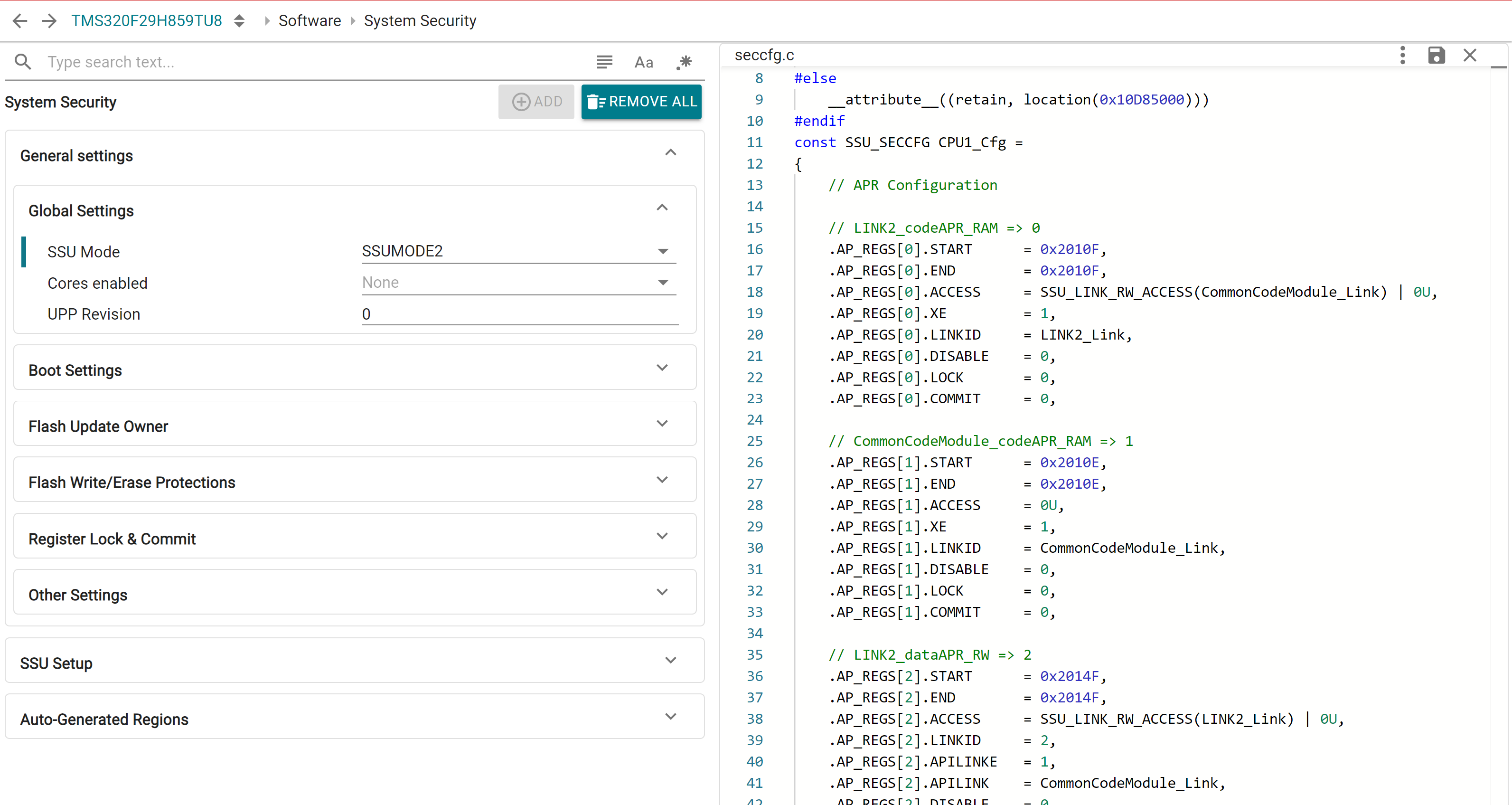
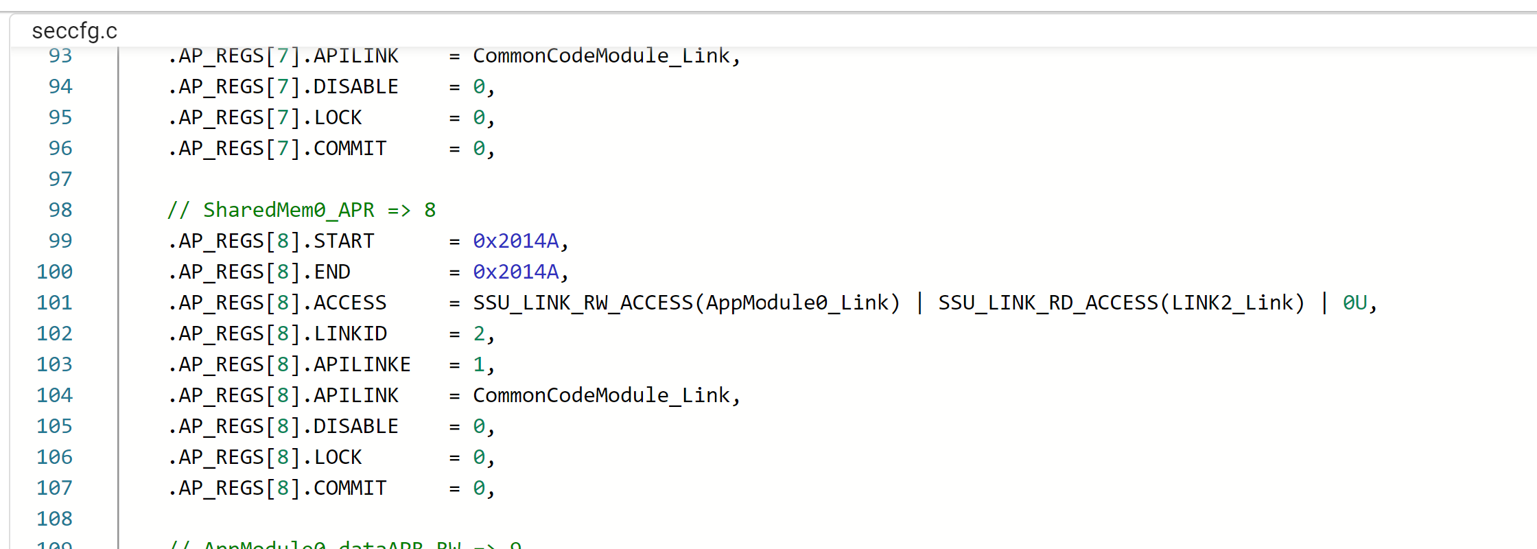
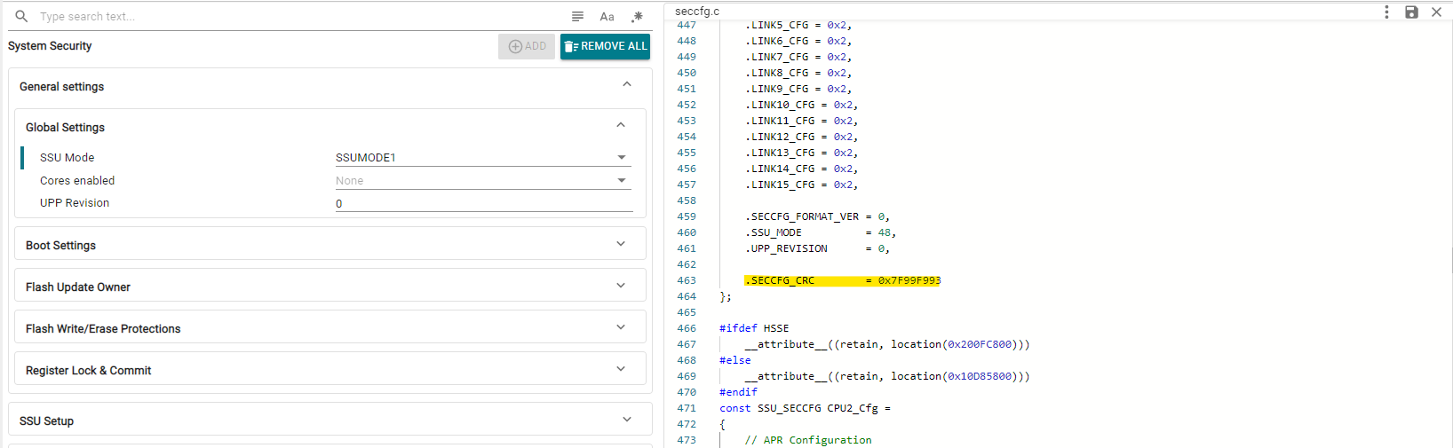
Apart from a custom linker command file, this profile generates a number of additional files, most importantly the seccfg.c file which contains the SECCFG settings for all cores as per user configuration. The CRC for the SECCFG is also computed as part of the Sysconfig tool.
The F29x-SDK also includes a post-build script for verifying SECCFG settings on application build, to minimize chances of error. This post-build step is included in the SDK SSU based examples, if user is developing own SSU based examples it is highly recommended to include this post-build step to avoid programming invalid SECCFG settings on the device and eventaully bricking it.

This module contains various configuration groups and easy setup options, allowing users to get security features up and running with minimal effort. Many of these settings are system-level specifications that must be defined by the primary core (CPU1), and as such, are not present in non-primary SysConfig contexts when operating in a multi-core environment.
This section contains several configurations that are device-wide and may be permanent/unmodifiable under normal runtime conditions. User must take care to set these up as per the requirements of the application.
Here, user can configure the SSU operation mode, which is the broadest specification of the level of safety and security features activated. Based on the selected SSUMODE, various additional configuration options may become available.
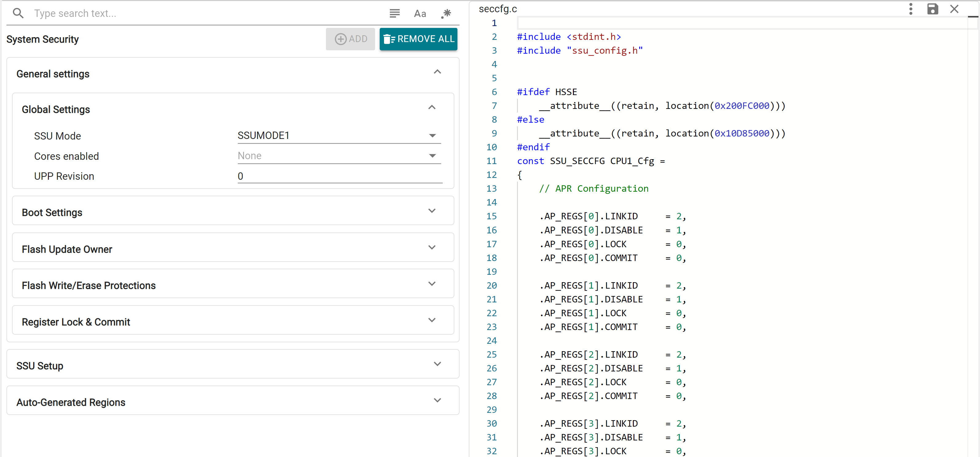
User can also configure the UPP Revision and enable other cores for System Security Configuration. For multi-core operation, the required cores must be enabled here by CPU1. Core-specific configurations can be done in the respective SysConfig contexts.
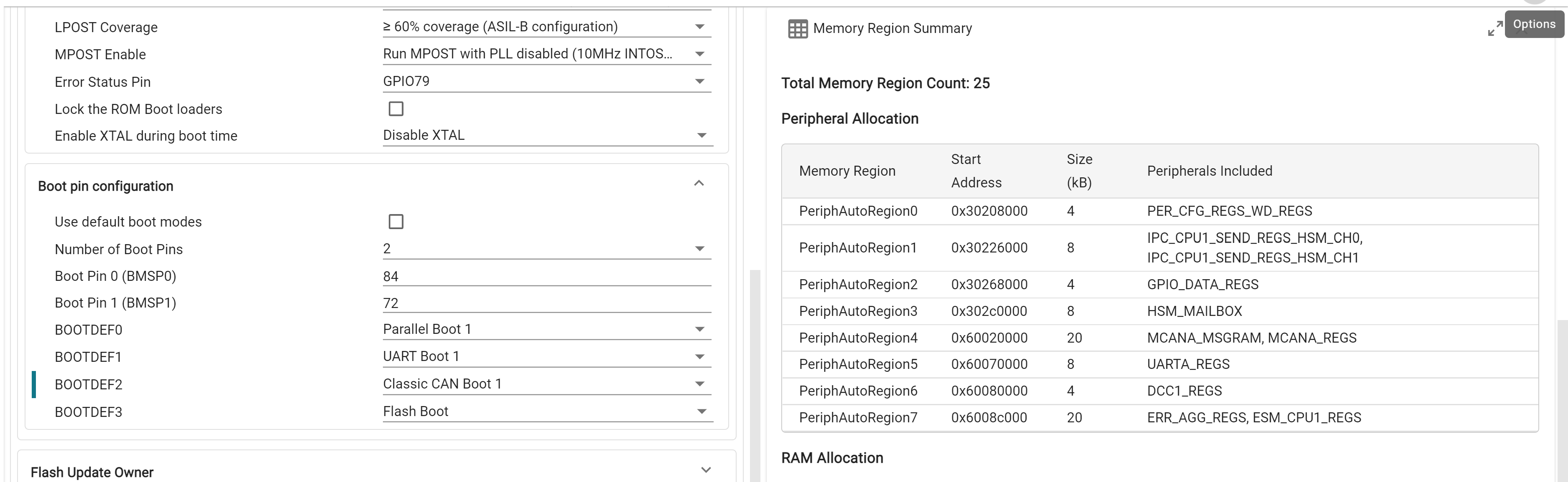
Device boot related configurations and boot pin combinations are customized here. The device default boot pin combination is available on launch, which can be customized by unchecking the "Use default boot modes" checkbox.
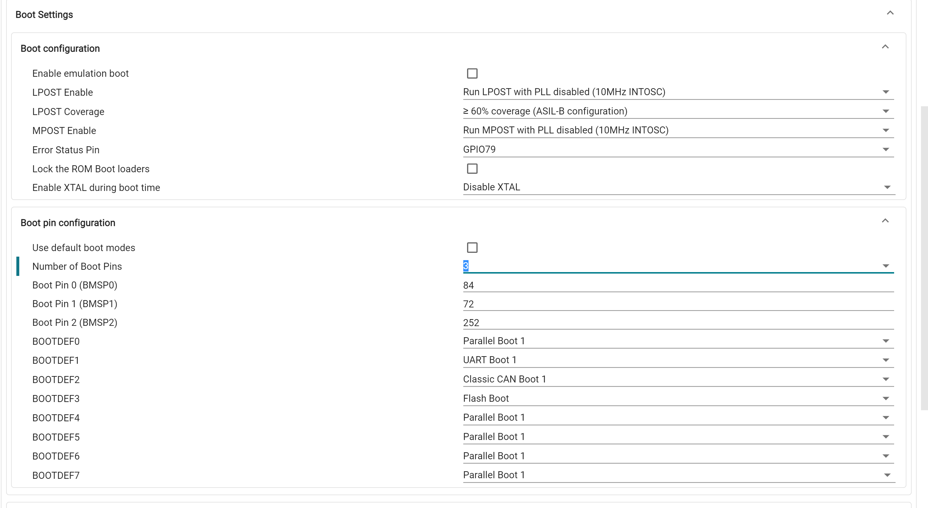
During device boot execution in LINK1, a specific combination of APR(s) is required to be already defined in SECCFG, the specifics of which vary based on the selected boot mode. To simplify this process, SysConfig will automatically create optimally segregated peripheral APR(s) based on selected boot settings and further application APR requirements. More information on peripheral APR auto-allocation is provided in the Application Module section
Flash update owners for SECCFG and each of the SSU ZONEs can be setup here. For each, user can configure the owner CPU and LINK, and whether flash updates are enabled.
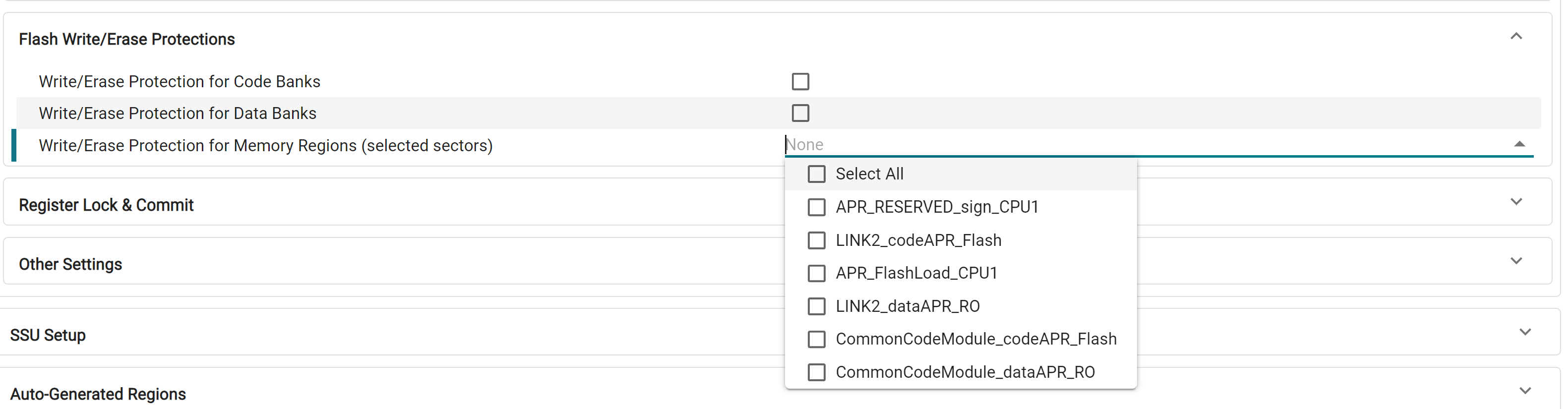
Write/Erase (WE) protections are configured here. This can be specified at a Code/Data bank level or customized for selected Flash Memory Regions. For each flash bank, individual WE protection can be done for the first 32 sectors, and in groups of 8 sectors for the rest of the bank. This is automatically handled by the tool, and memory regions are allocated to allow flexibility in individual WE protection configuration.
Here, user can specify C29-level and ZONE-level debug authorization and passwords. This is only configurable in SSUMODE3.
Lock and commit settings for various SECCFG registers are done here. This include settings that may be unmodifiable until the next device reset and must be configured carefully.
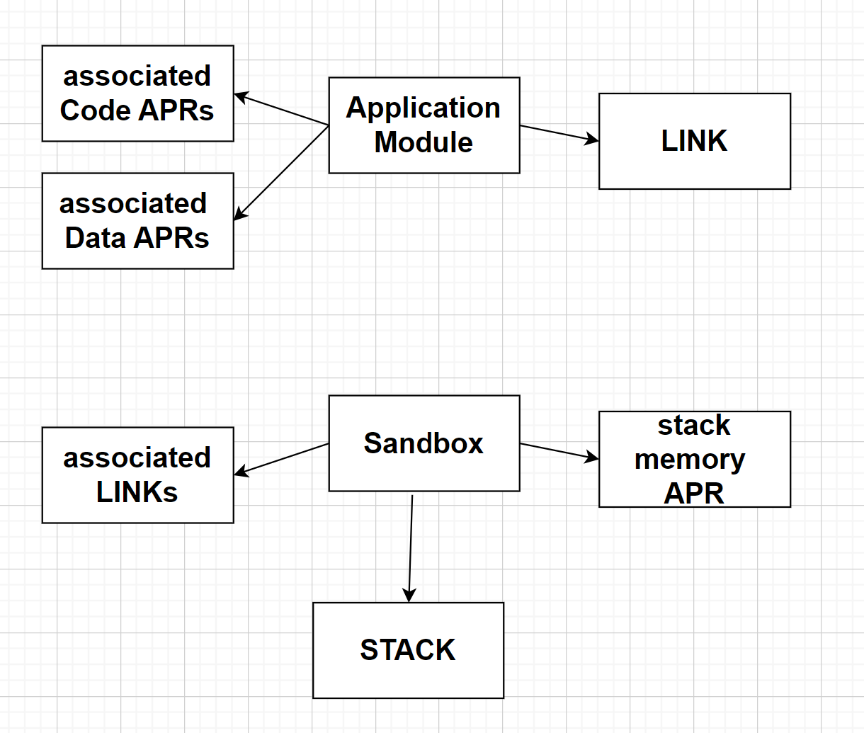
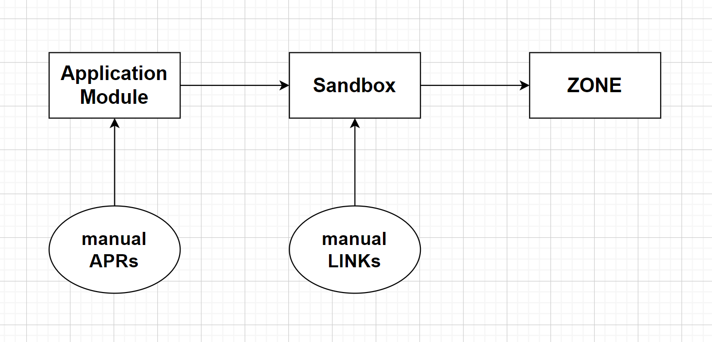
This section, available under the "SSU Setup" tab, allows the user to configure Application Modules, Sandboxes and Shared Memory Regions. The diagrams below relate these software terms to the hardware concepts of APR, LINK, STACK and ZONE.

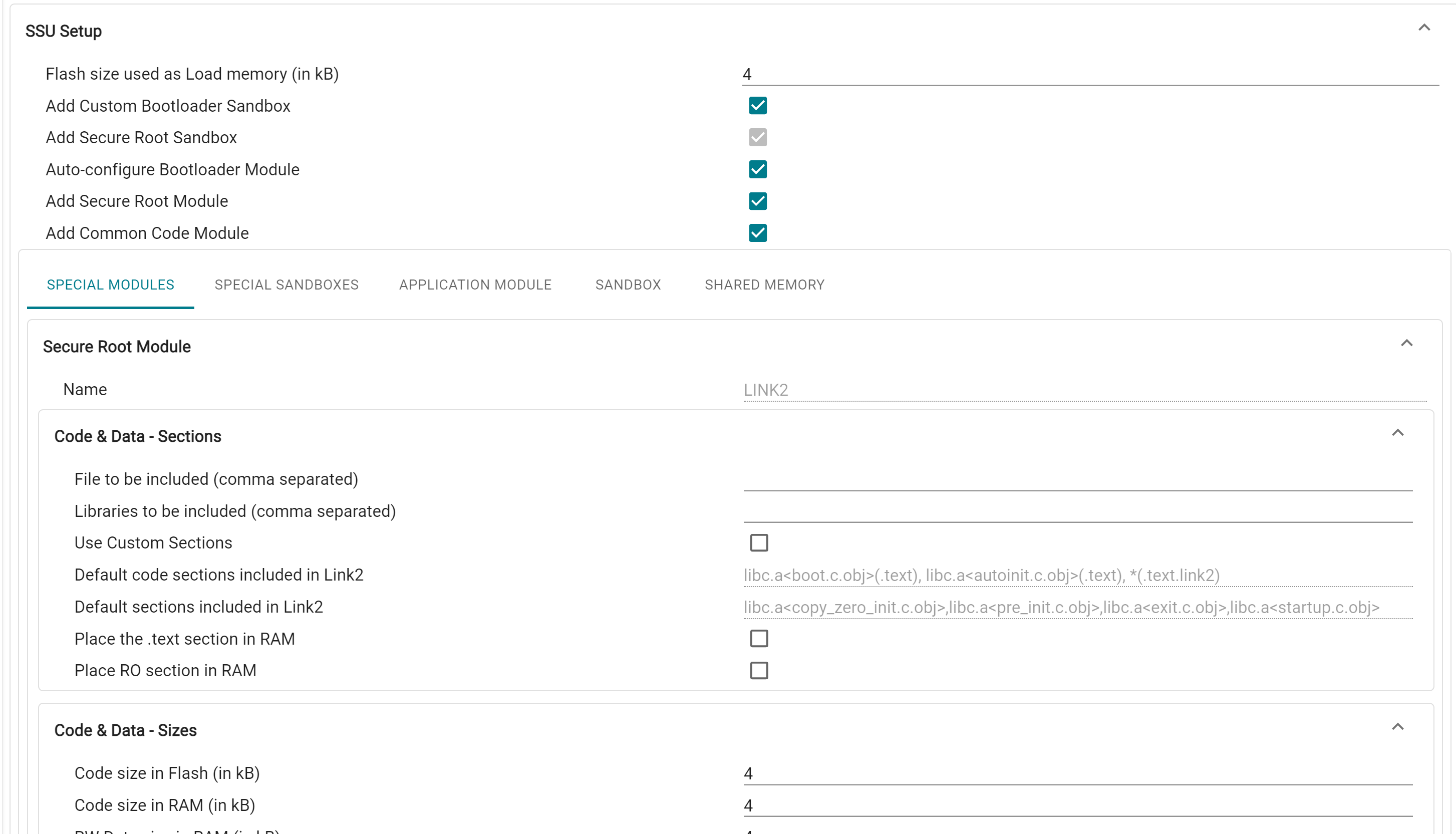
At the top-level, user can specify the size of the Flash APR to be used as Load memory for sections such as .cinit, .binit and copy tables. The user can also enable/disable a number of "special" Application Modules and Sandboxes, which are detailed in a below section.
An Application Module is a basic partition of a system application. Each module consists of a single LINK, one or more code memory APRs (Memory Regions) containing the LINK’s code, all data memory APRs associated with the LINK, and all peripherals and interrupts associated with the Application Module. Typically, the code APRs contain .text and other linker output sections containing code, and the data APRs contain .bss,.const and other linker output sections containing data and variables.
User can enter the files and libraries to be included in each application module, and further specify custom code and data sections on top of the default ones.
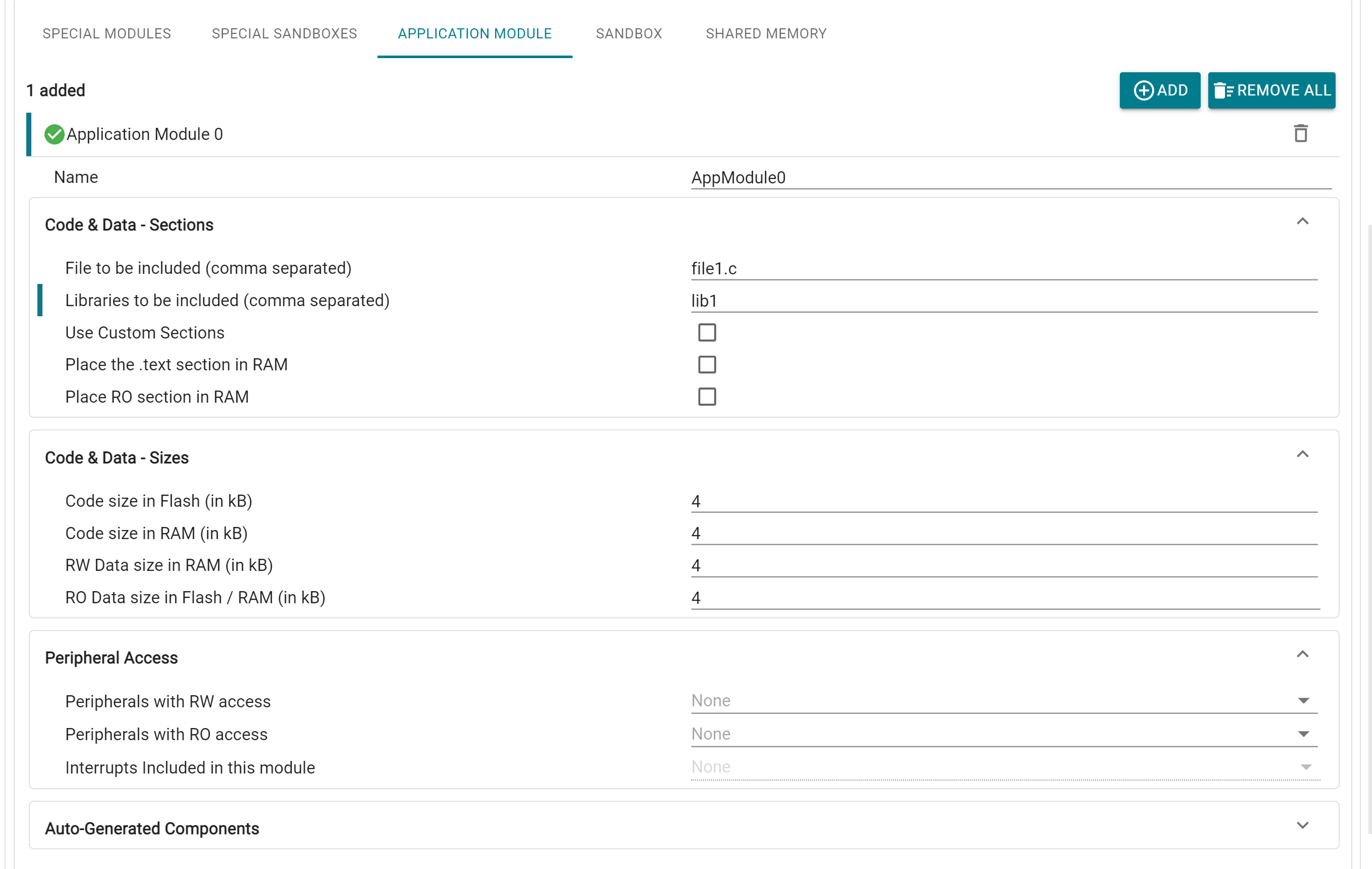
For each application module, up to 4 APRs can be configured by adding their sizes:
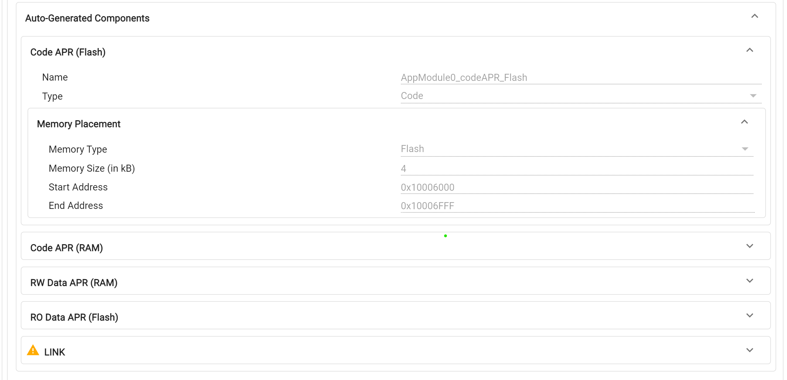
Availability of these regions is dependent on the current core and BANKMODE configurations
If any of these APRs is not required, it can be removed by specifying the corresponding size as 0. There is also the option to place certain sections entirely in RAM, and combine RW data sections, available in the Sections tab. As with memory regions, the placement of these APRs in RAM/Flash memory is automatically handled by the tool.
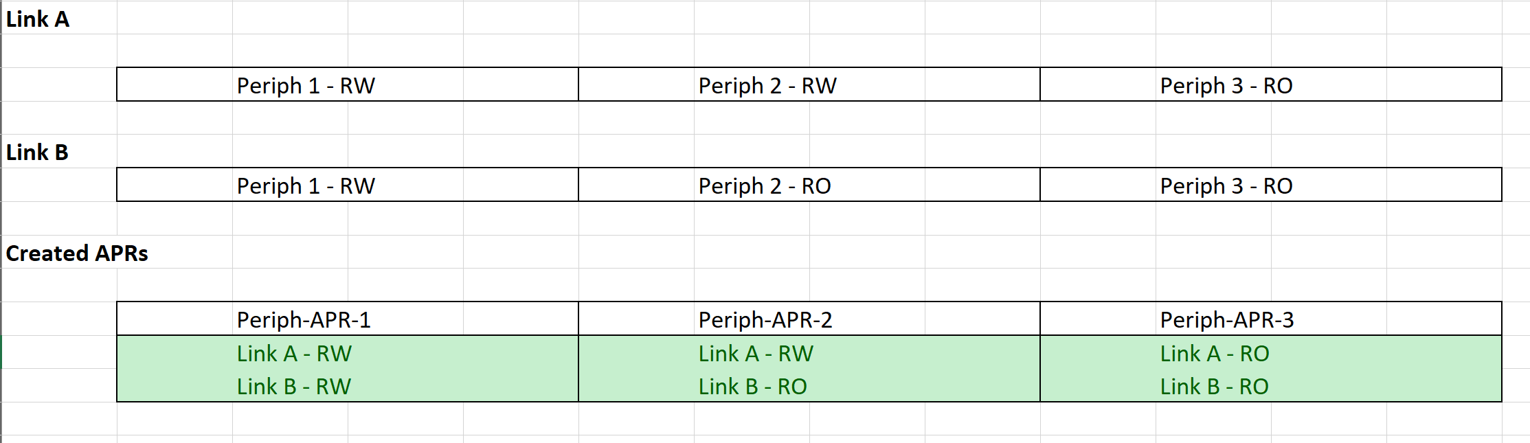
For each Application Module, user can grant Read-Only (RO) and Read-Write (RW) access to relevant peripherals. It is possible for there to be overlap in peripherals between modules, leading to the requirement for a number of APRs with different access permissions. In order to simplify the experience for the user and minimize the APR usage, the tool will automatically create Peripheral APRs for each CPU based on the access permissions given for every Application Module. These regions are "implicitly" created and can be viewed by opening the Memory Summary view in the tool.
In case the user is dissatisfied with the automatic peripheral APR combination done by the tool, they can create APRs manually through the Memory Regions window in Sysconfig, then provide appropriate access in the LINK window. Note that the same peripheral cannot be included in automatic and manual APR creation
Interrupts belonging to each Application Module can also be configured in the "Peripheral Access" subsection.
All the generated Memory Regions (except the auto allocated Peripheral APRs) and the associated LINK can be found in the Auto-Generated Components tab and are also available in their respective SysConfig module pages.
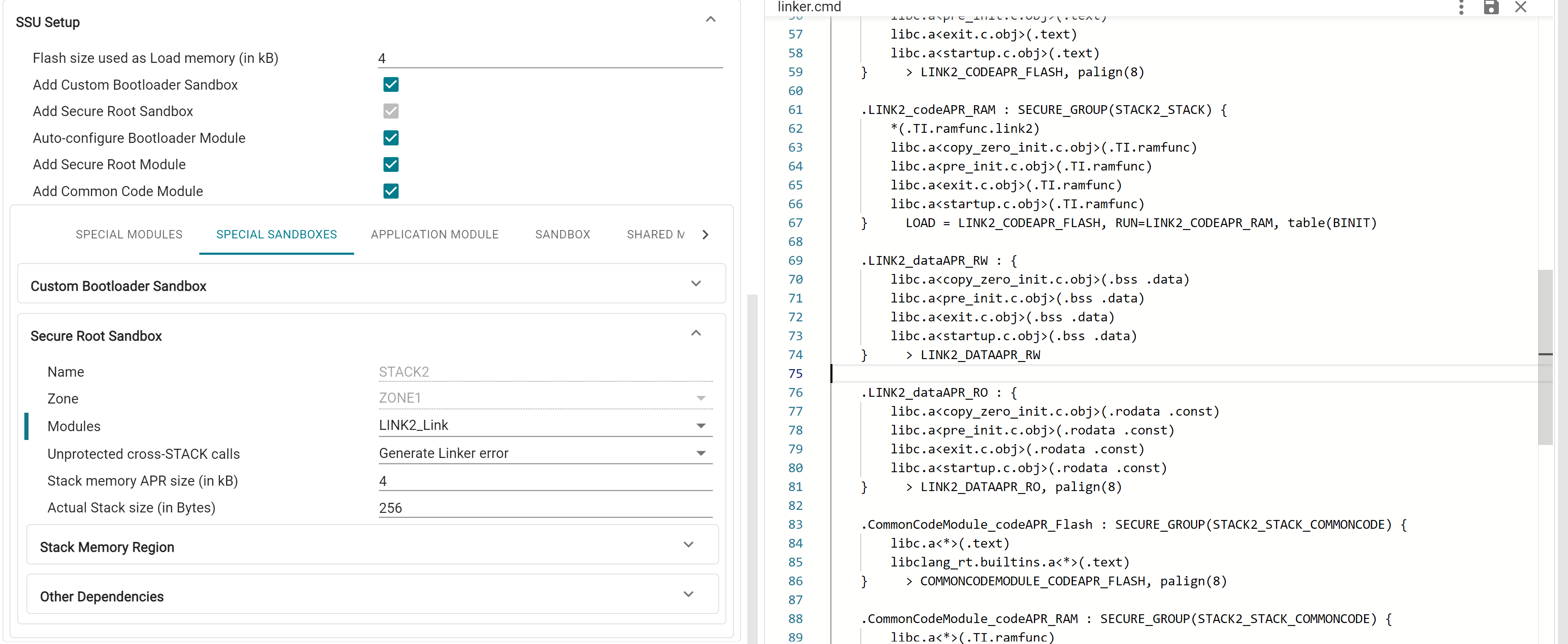
Sandboxes provide security and safety isolation within a CPU. Each Sandbox is associated with a STACK, and a stack memory APR in the SSU. Each sandbox has a dedicated physical stack pointer in the CPU that is inaccessible by other sandboxes, and a dedicated stack memory APR with read/write permissions restricted to only code belonging to that sandbox. Special C29 CPU gate instructions are required when crossing from one STACK to another. Each STACK belongs to one ZONE, but a ZONE can contain multiple STACKs.
For a Sandbox, user can specify the Application Modules that are in the corresponding STACK, and the ZONE that the STACK belongs to. Due to the design of APRs limiting granularity to 4kB, user can specify the "Actual Stack Size" to be used in bytes. The created stack memory APR will be RW accessible to all the LINKs in the STACK, and the remaining space can be used store additional data sections, which can also be configured in the Stack Memory Region tab.
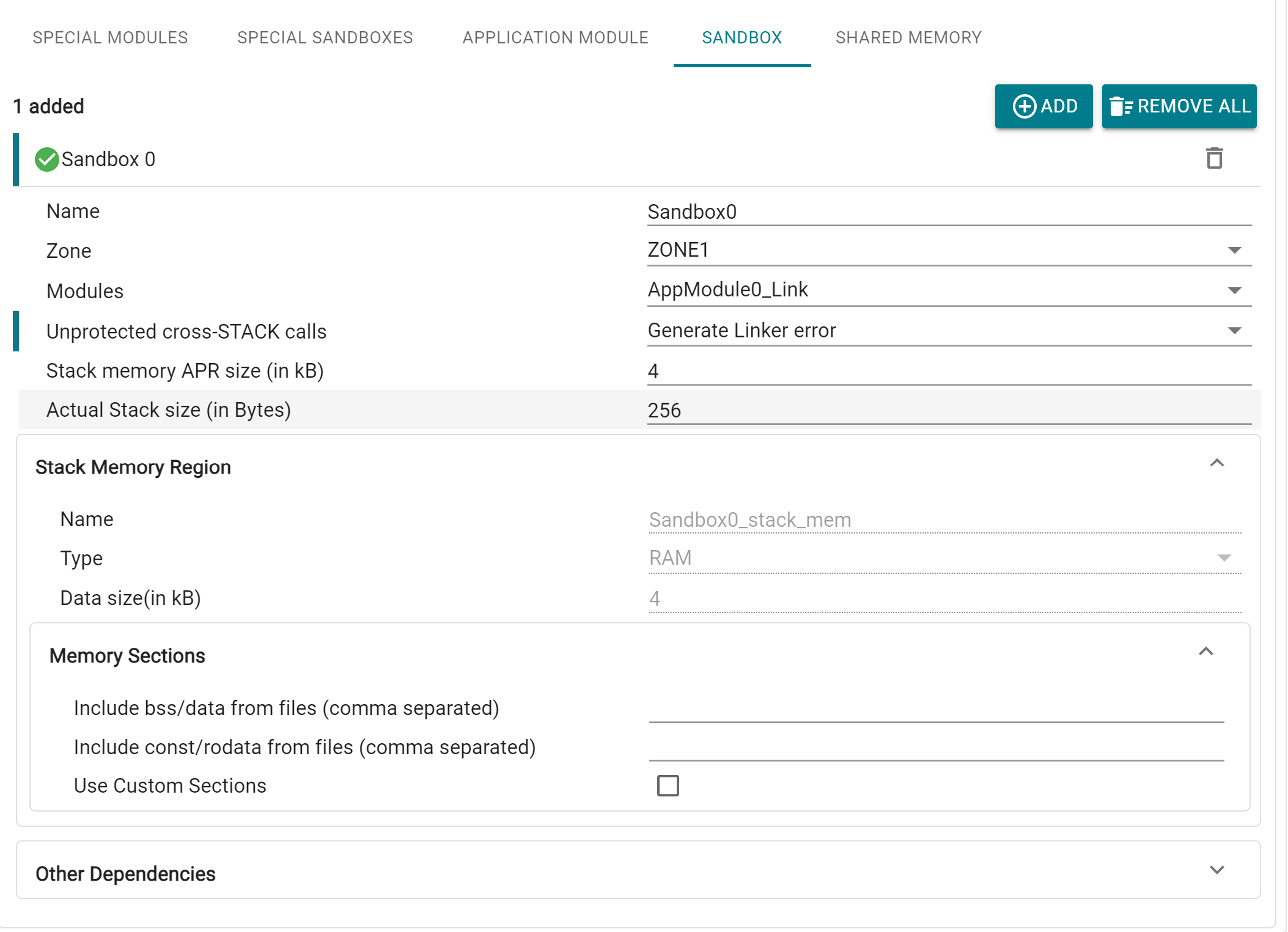
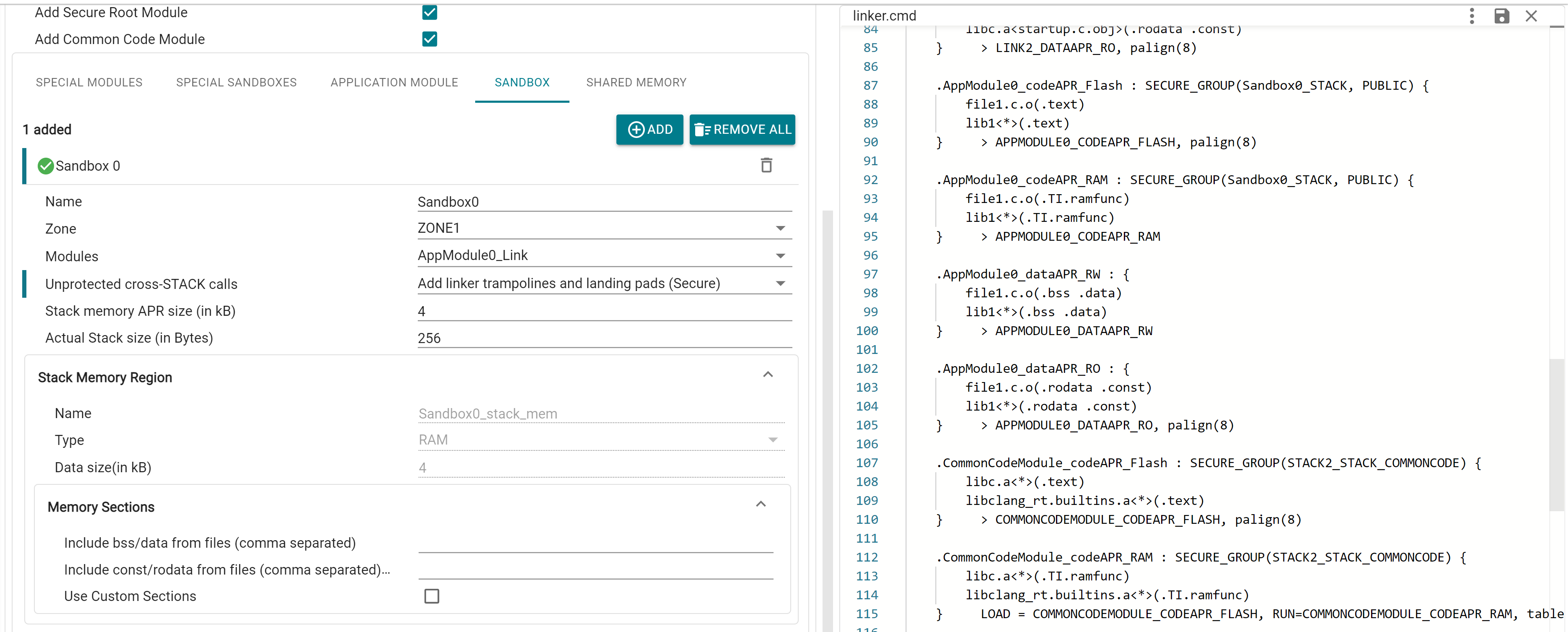
Code sections placed in each STACK are placed in separate Secure Groups. The desired behavior for unprotected cross-STACK calls can also be setup here, i.e. whether linker error is generated (PRIVATE, which is the default setting), or linker generates trampolines and landing pads (PUBLIC / PUBLIC_TRUSTED)
A Sandbox for STACK2 is added by default in System Security, since this is the primary User STACK used by the application.
This tab contains the option to setup a number of "special" Application Modules and Sandboxes that are commonly present in every application, with preconfigured settings for each of them. These special modules are added by default but can be removed (other than STACK2) by unchecking the checkbox based on application need.
This is the Bootloader STACK, which is always enabled in hardware. In order to set up custom bootloader, user can enable this module in Sysconfig. STACK1 can optionally be used in application. Bootloader Module (LINK1) is always associated with STACK1, and STACK1 is always in ZONE1
This is the primary user stack with secure root permissions, and is always enabled. Secure Root Module (LINK2) is always associated with this Sandbox
This is the Bootloader LINK, which can optionally be used in application. LINK1 is granted access to certain peripheral and device configuration registers based on the selected boot mode combinations, which is automatically added by the tool. These regions are mandatory for device booting, therefore the tool will throw error if LINK1 is not granted access to these regions (either through the Application Module dropdown, or through manually created peripheral APRs). The below picture shows an example of 4 configured boot modes, and the auto-created peripheral APRs for this combination
LINK1 also has RO access to the Flash Certificate APR, which is always placed at 0x10000000
This is the primary user LINK used in application. CPU1.LINK2 is the system security root LINK (SROOT) and has special fixed permissions that enable access to system configuration registers and override controls. Sections from the F29 driverlib that need security root permissions, and libraries like libc.a are placed in this module by default.
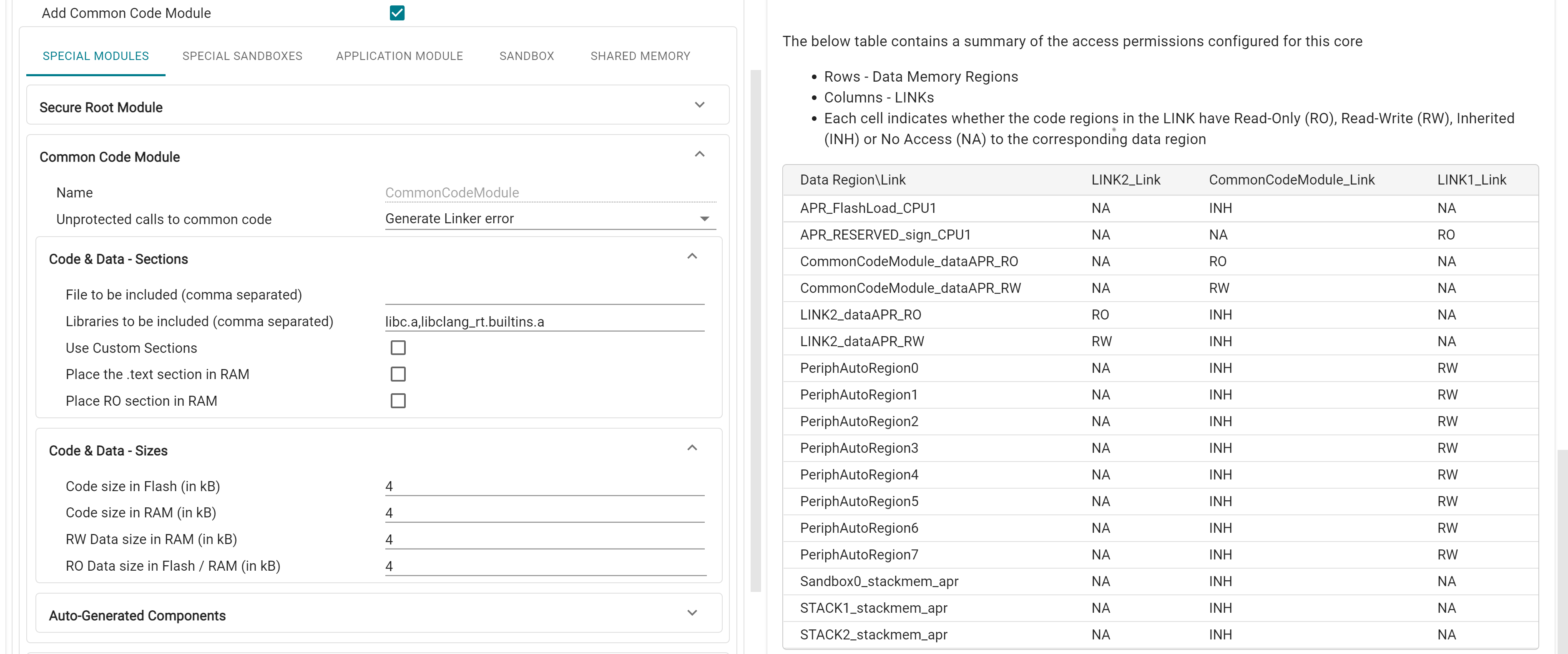
This Module can be used for libraries or functions that are used across modules (such as F29 driverlib) can be placed in this module. This Module is granted Access Protection Inheritance (API) by default, i.e. it inherits the caller module's accesses to memory regions and peripherals. Common Code Module cannot be granted direct access to peripherals, it instead inherits these as well.
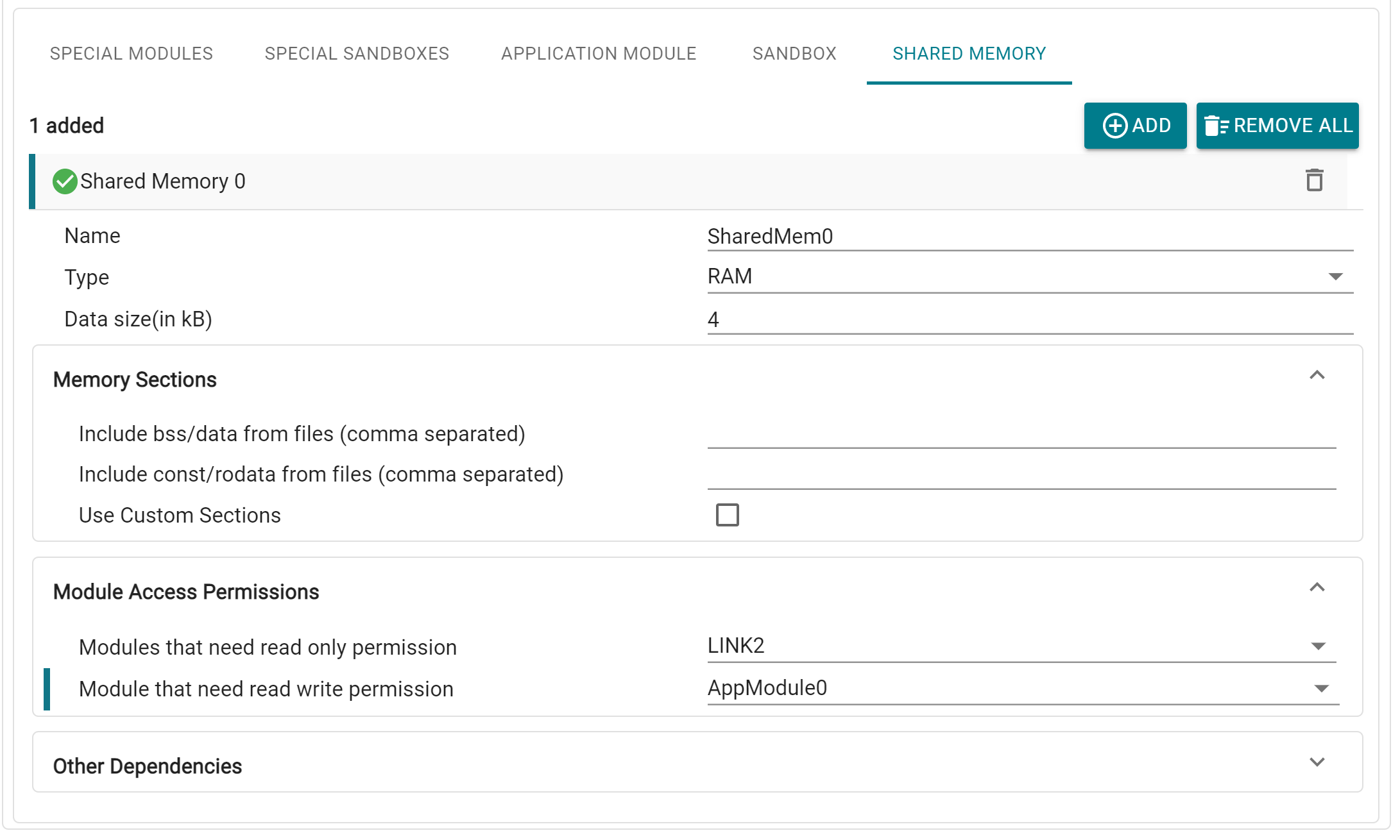
Shared Memory regions are special APRs that are accessible by multiple Application Modules. Adding this module creates a Data Memory Region in RAM/Flash, for which user can specify the Application Modules that need RO and RW permissions. Data sections can also be customized.
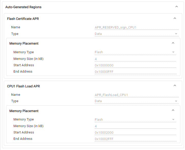
System Security also automatically generates the APRs for the CPU1 Flash Certificate (which must always be placed at 0x10001000), and each core's Flash Load APR, which can be viewed under the Auto-Generated Regions tab.
The 'APR_FlashLoad_CPU1' and 'APR_FlashLoad_CPU3' are created by default which are used to place the binit and cinit tables. This is data APR in Flash with no access to any links. The routine in compiler which copies the binit and cinit tables from Flash to RAM enables 'LINK2_AP_OVERRIDE' privilege so that LINK2 gets Read/Write access to these APRs to copy the binit and cinit tables
There is an option to disable creation of this APR by making its size 0, in which case the default binit and cinit sections are NOT created in the tool generated linker command file, and user should make sure to add these section explicitly.
Pl. refer to the compiler documentation for more details on the binit and cinit tables
In the System Security Configuration profile, Memory Regions are equivalent to APRs. Apart from the auto-generated APRs configured through SSU Setup, additional custom APRs can also be added in the Memory Regions page in SysConfig. With System Security enabled, user also has the ability to create Peripheral Memory Regions. Here, unlike the peripheral setup in Application Modules, the peripherals selected for an APR must be contiguous in memory, since they need to be covered in a single region. The selected peripherals must also not have any conflicts with the auto-allocated peripheral APRs.
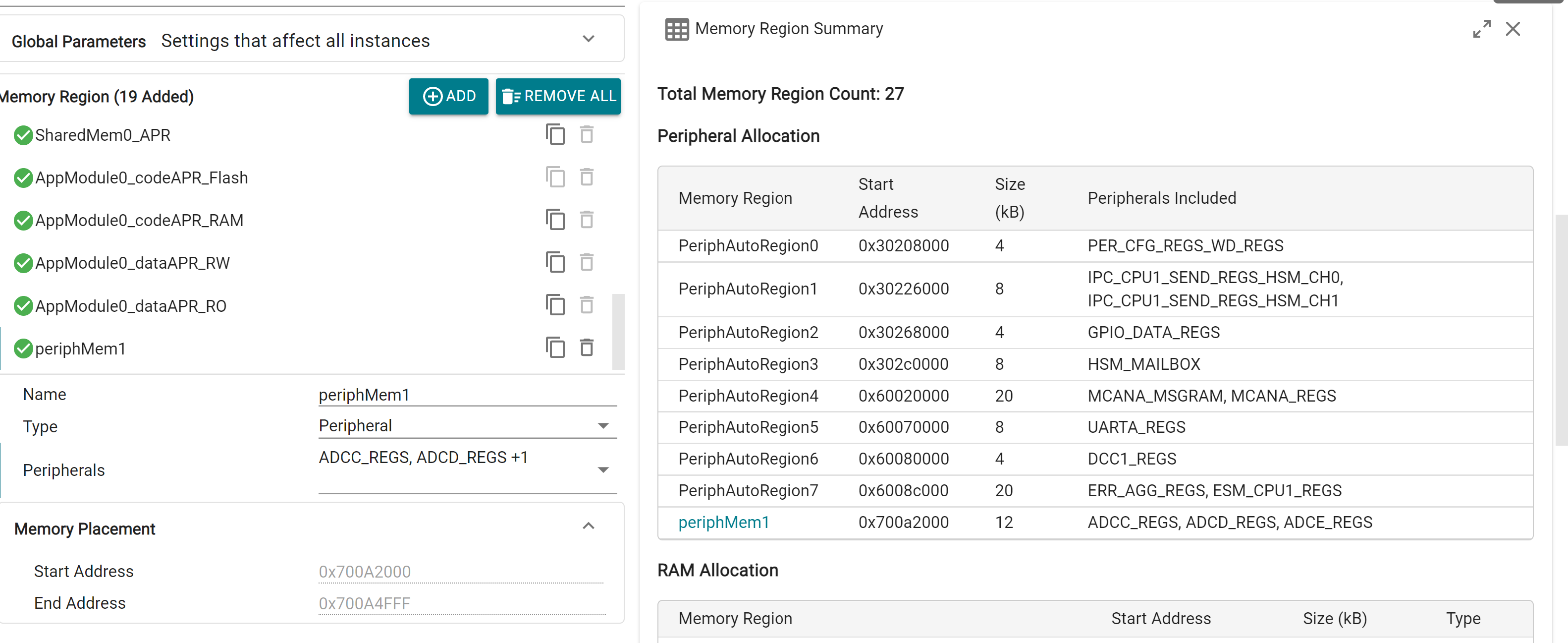
Remaining Memory Region configurations remain largely the same. A total of 64 APRs per core can be added on SysConfig. However, since a number of APRs are created "implicitly", they are not directly visible in the Memory Regions module page. A full list of created APRs can be viewed in the Memory Summary view, which is explained further in the main page.
Sections module functions the same as in Memory Allocation profile.
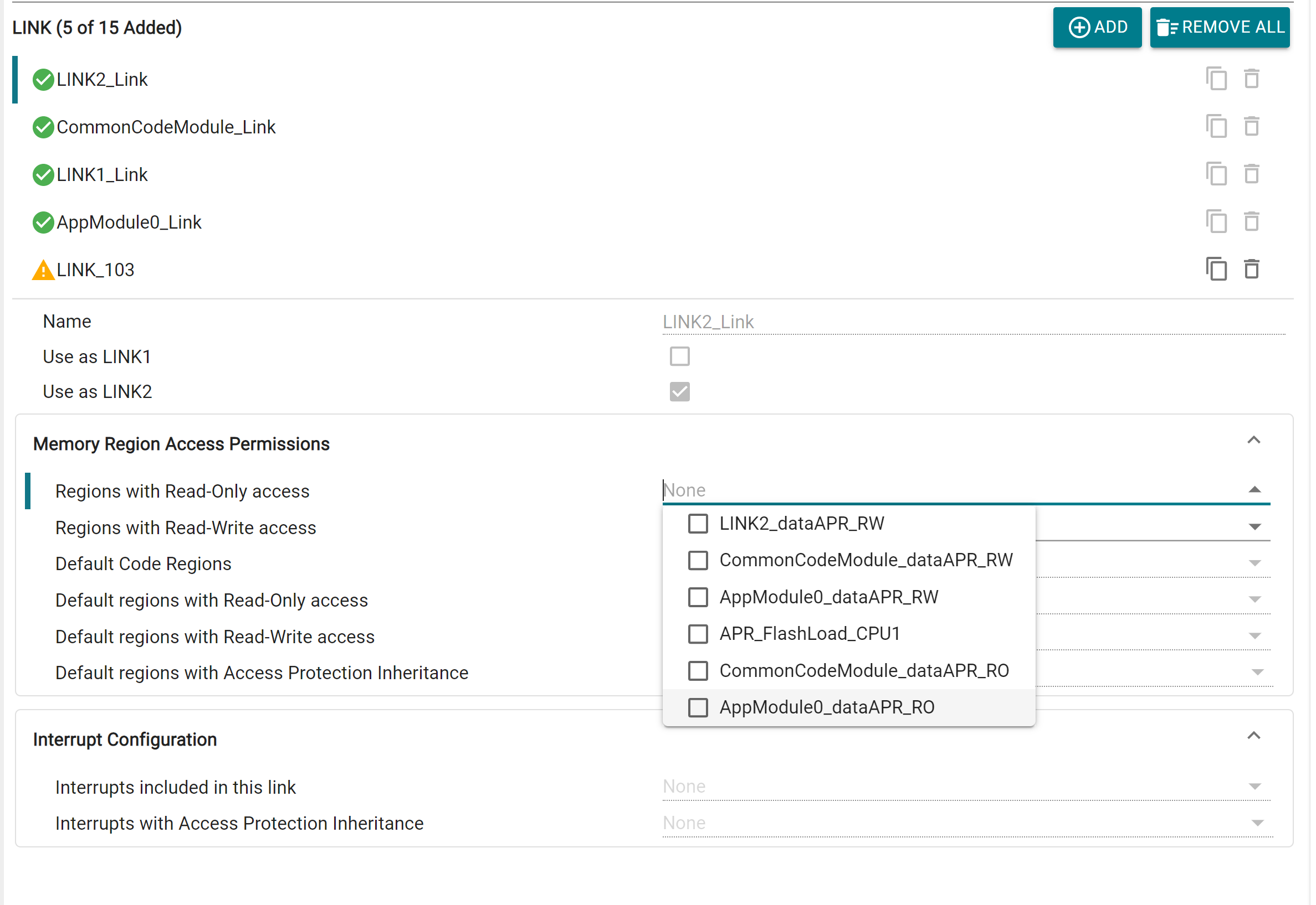
Aside from the LINKs auto configured through Application Modules in Quick Setup, additional custom LINKs can also be added. Each LINK has customizable access permissions for Memory Regions, and Interrupt configuration. There is also the option to designate a LINK as LINK1 or LINK2 (if these haven't been already configured through Quick Setup or another LINK instance). This will automatically assign the LINK certain special permissions based on the selection. Up to 15 LINKs per core can be added via SysConfig.
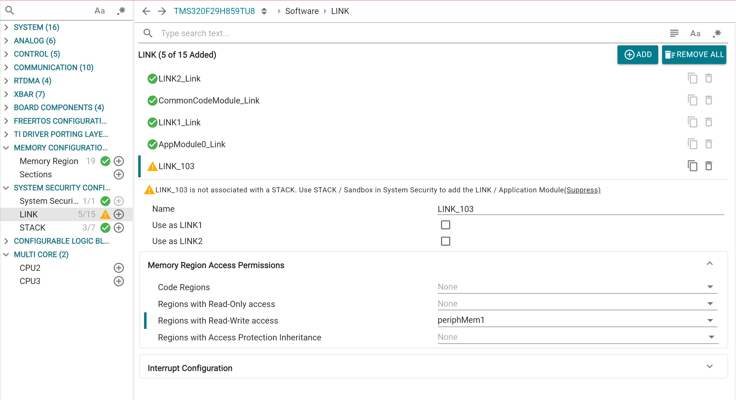
For LINKs created via Application Modules, additional region permissions can also be added from here
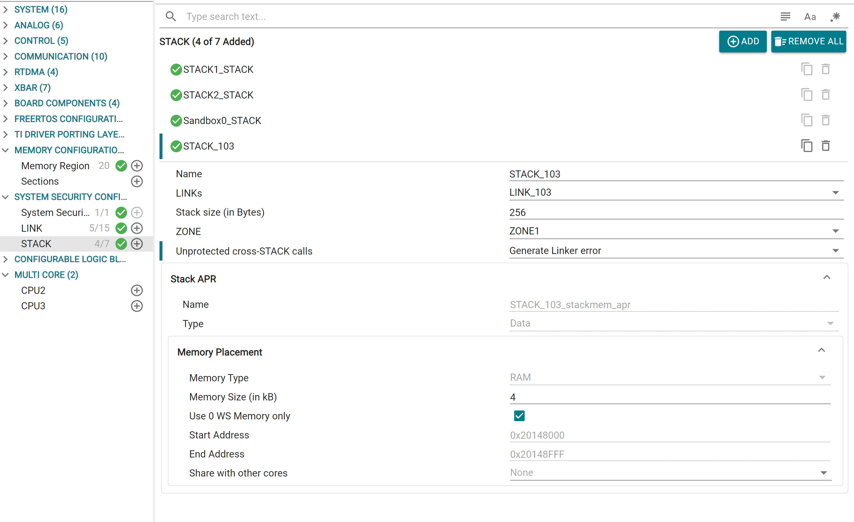
Similarly, outside of the Sandbox generated STACKS, user can add custom STACK modules directly in SysConfig. Configurations remain the same as Sandbox. Up to 7 STACKs per core can be added via SysConfig.
INT uses the software stack that is configured in the INTSP register.
CPU will only acknowledge the INT when its current execution stack matched with INTSP
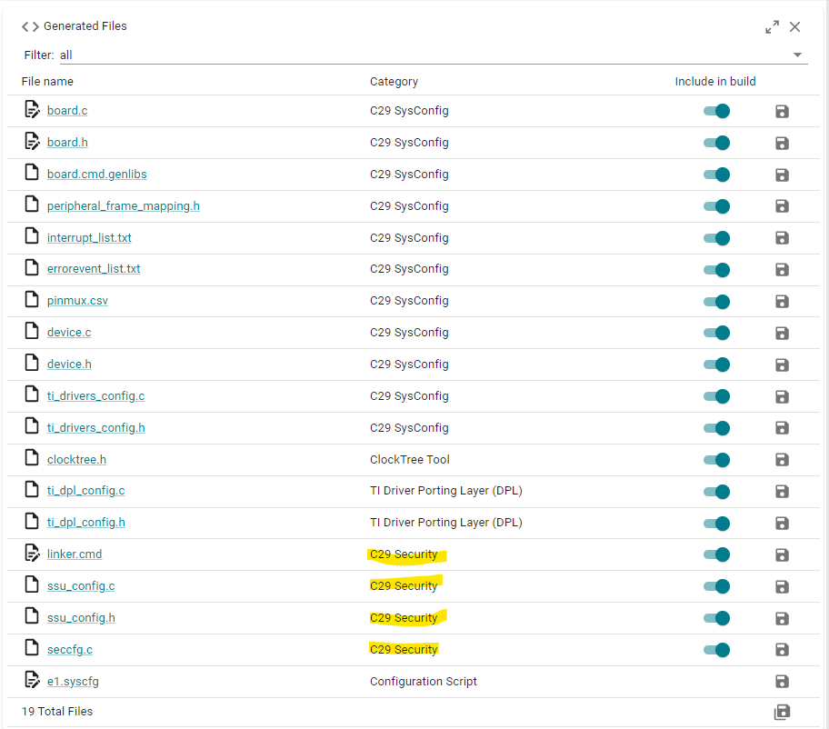
The System Security Configuration profile generates a number of files, which can be found under the "C29 Security" category.
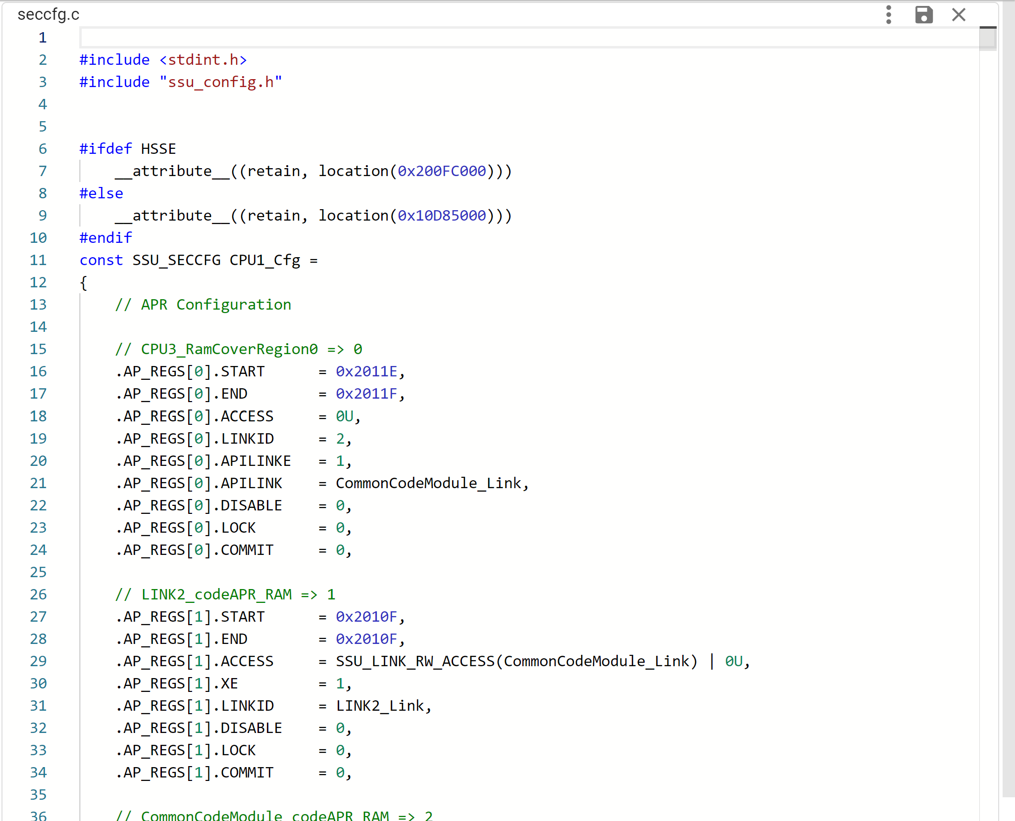
The seccfg.c file contains all the configured user protection policy settings, SSU configurations and boot settings for the core, in a C structure format. These are programmed into the NONMAIN Flash SECFFG region of each core. The SECCFG address is programmed at different addresses depending on current BANKMODE, which is handled by the tool. To protect the integrity of the SSU user protection policy, the SECCFG sector also includes a CRC value that is checked at boot time. This CRC is auto calculated by the tool.
In SSUMODE1, SECCFG settings related to APR, LINK and STACK are configured to their default values. Remaining SSU settings can be configured.
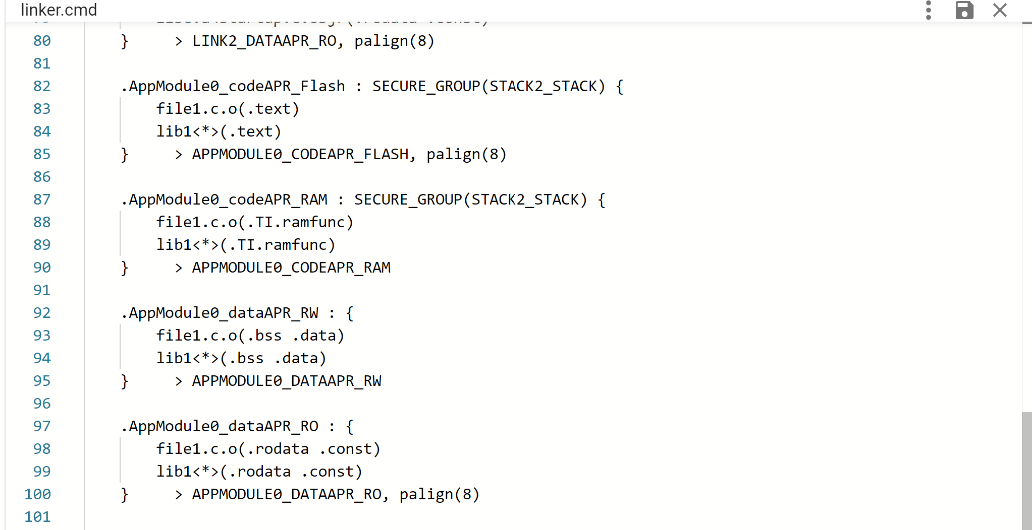
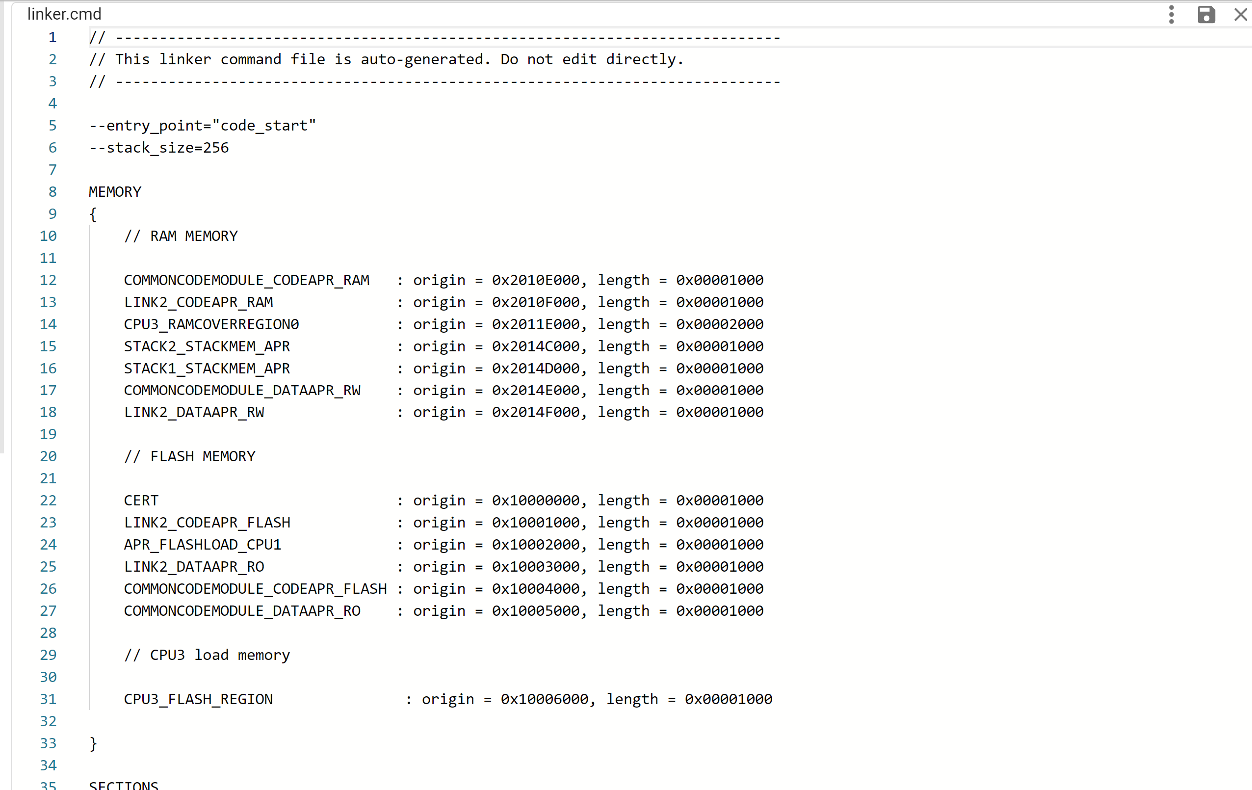
The tool generates the linker.cmd file based on the selected options in the GUI. For user-defined Sections, entries will only show up when that specific section has a valid “Load Memory” entry selected
For System Security Configuration profile, Sections are automatically inserted for each configured APR, based on the type of data is contains. Appropriate SECURE_GROUP tags are also automatically inserted by the tool
In case of Multi-Core System Security Configuration, additional memory regions are generated on CPU1. This includes a Flash Memory region covering the Flash data of other cores, and a RAM-cover region spanning the Data RAM of other cores. These regions are used by CPU1 during runtime to copy Flash data to RAM for cores that don't have Flash access
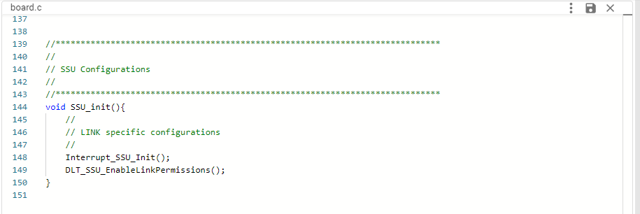
The header file provides macros for every APR, LINK and STACK which can be used in application. ssu_config.c configures the functions for setting up Interrupt-LINK mapping and enabling DLT FIFO access for LINKs.
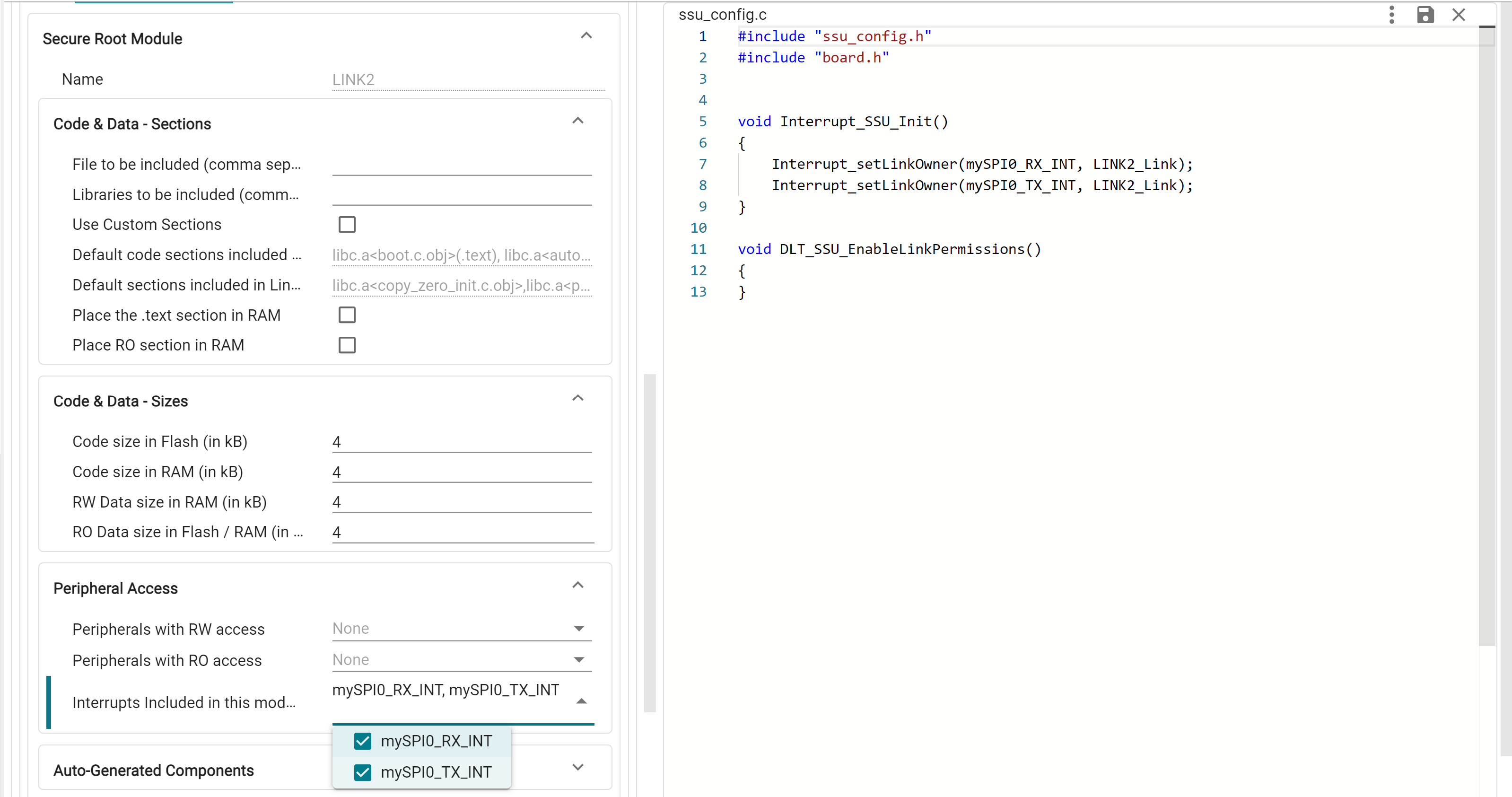
These functions are bundled under the SSU_init() available from board.h, which must be called in application to initialize these settings
 1.11.0