← Back to Reference Designs Overview
Target Applications
- DC charging (pile) station
- EV charging station power module
- Energy storage power conversion system (PCS)
- On-board (OBC) and wireless charger
Features & Specification
- Smart Gate driver UCC21710 providing integrated protection for SiC MOSFETs
- TMS320F280039 controller for implementation of digital control
- Primary voltage of 700V to 800V DC, secondary voltage of 350V to 500V DC (SPS) 250V to 500V (EPS)
- Achieves peak efficiency of 98.7% and full load efficiency of 98%
- PWM switching frequency of 100kHz and reduced transformer size enabled by planar magnetics
- Maximum power output of 10kW
| TIDA-010054 Design Specification |
| Vin (Min) (V) | 700 |
| Vin (Max) (V) | 800 |
| Vout (Nom) (V) | 250-500 |
| Iout (Max) (A) | 26 |
| Output Power (W) | 10000 |
| Isolated/Non-Isolated | Isolated |
| Input Type | DC |
Description
This reference design provides an overview on the implementation of a single-phase dual active bridge (DAB) DC/DC converter.
DAB topology offers advantages like soft-switching commutations, a decreased number of devices and high efficiency. Modularity and symmetrical structure in DAB allow for stacking converters to achieve high power throughput and facilitate a bidirectional mode of operation to support battery charging and discharging applications.
This design is beneficial where power density, cost, weight, galvanic isolation, high voltage conversion ratio and reliability are critical factors, making it ideal for EV charging stations and energy storage applications.
This design can be run on a C2000™ TMS320F280039C real-time MCU.
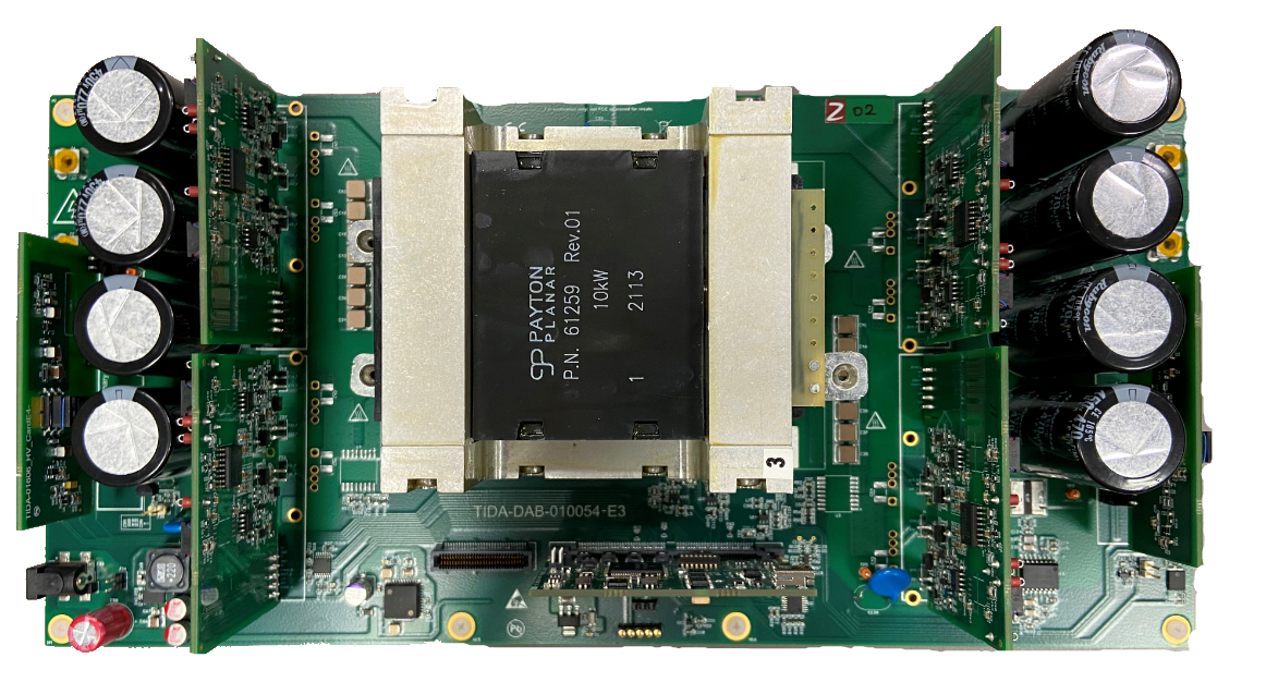
TIDA-010054 EVM Board
|
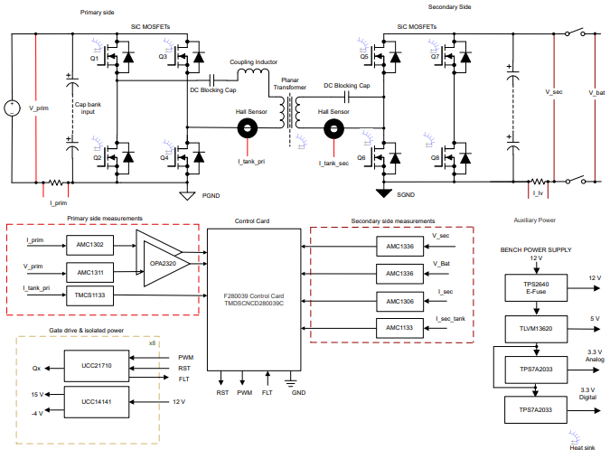
C2000 MCU interface to PCMC PSFB DC/DC Power Stage Diagram
|
Relevant Links
Useful links regarding the reference design are provided below:


- Note
- To import and evaulate CCS project using the button above, please access the current page via Resource Explorer from Code Composer Studio (CCS), or CCS Cloud. (go to CCS->View->Resource Explorer)
Steps to Run the Example
- It's strongly recommended to first read through the User Guide/Software Guide for any specific setup instructions and hazard warnings before proceeding.
- To import CCS projects, either import via the button above or mannually select the file directory where this solutions resides.
- Build the project within the CCS project menu, then launch a CCS debug session and run the executable.
Release Notes
Shown below lists all the software revision history for this reference design:
| Software Version | SDK Release | Changelog |
| v1.00.00 | 3.03.00.00 | First release, on F28004x devices in C2000Ware Digital Power SDK |
| v1.01.00 | 4.00.00.00 | Bug fixes & Enhancements:
- Change compiler version (from v20.2.1 to v21.6.0)
- Add source-lookup path for driverlib
|
| v1.02.00 | 4.03.00.00 | Changes & Enhancements:
- Software updates to device.c, device.h, driverlib.h to account for changes in C2000Ware
- Projectspec updates to account for changes to Kit.json output from sysconfig tool
- Changed compiler version (from v21.6.0.LTS to v22.6.0.LTS)
|
| v2.00.00 | 5.00.01.00 | New device support & Enhancements:
- Added F28003x as a supported device
- Added support for extended-phase shift
|
| v3.00.00 | 5.02.00.00 | Updated device support & Enhancements:
- Updated software to support new HW Revision TIDA-010054E4
- Additional protection with smart gate drivers
- Secondary side sensing with isolated delta-sigma modulators instead of isolated amplifiers. ADC interface on C2000 replaced with the SDFM peripheral.
- Relays to disconnect secondary side output.
- Closed loop voltage and closed loop current control mode for reverse direction power flow.
- Deprecated support for F28004x, only F28003x device will be supported
|
| v3.01.00 | 5.03.00.00 | Bug fixes:
- Fixed an PWM issue, which could lead to skip one PWM cycle for phase shifts greater than 0.5. This led to an unexpected rise in current, which tripped the system.
|
Hardware design files
For EVM design files such as schematics, BOM, PCB layouts & assembly files, please visit TI design webpage from the link above.
Help and Support
For additional help and support, please visit TI E2E™ design support forums


 1.8.17