Device Functions
Introduction
This chapter describes the various API layers within the USB library that offer support for applications wishing to present themselves as USB devices. Several programming interfaces are provided ranging from the thinnest layer which merely abstracts the underlying USB controller hardware to high level interfaces offering simple APIs supporting specific devices.
File Structure
Filename |
Description |
|---|---|
|
The header file containing device mode function prototypes and data types offered by the library. This file is the main header file defining the USB Device API. |
|
The header file defining the USB generic bulk device class driver API. |
|
The header file defining the USB Communication Device Class (CDC) device class driver API. |
|
The header file defining the USB Human Interface Device (HID) device class driver API. |
|
The header file defining the USB HID keyboard device class API. |
|
The header file defining the USB HID keyboard device class API. |
|
The source code for the USB device enumeration functions offered by the library. |
|
The source code for the USB device interrupt handler. |
|
The source code for the USB device configuration functions. |
|
The source code for functions used to parse configuration descriptors defined in terms of an array of sections (as used with the USB Device API). |
|
The source code for the USB generic bulk device class driver. |
|
The source code for the USB Communication Device Class (CDC) device class driver. |
|
The source code for the USB Human Interface Device (HID) device class driver. |
|
The source code for the USB HID keyboard device class. |
|
The source code for the USB HID keyboard device class. |
|
The private header file containing definitions shared between various source files in the device directory. Applications must not include this header. |
|
The header file defining the USB composite device APIs |
|
The source code for USB Composite device |
|
The header file defining the USB HID Sensor device APIs |
|
The source code for USB Sensor device |
|
The header file defining the USB MSC device class APIs |
|
The source code for USB MSC device class |
API Choices for USB Devices
The USB library contains four API layers relevant to the development of USB device applications. Moving down the stack, each API layer offers greater flexibility to an application but this is balanced by the greater effort required to use the lower layers. The available programming interfaces, starting at the highest level and working downwards, are:
Device Class APIs
Device Class Driver APIs
The USB Device API
The USB DriverLib API
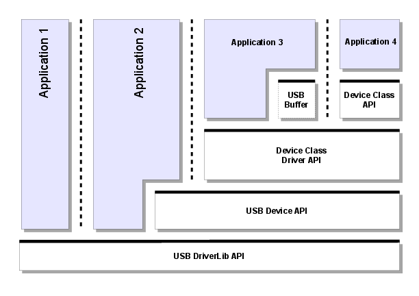
Fig. 1 USB Device Block Diagram
In the above diagram, bold horizontal lines represent APIs that are available for application use. Four possible applications are shown, each using a different programming interface to implement their USB functionality. The following sections provide an overview of the features and limitations of each layer and indicate the kinds of application which may choose to use that layer.
USB DriverLib API
The lowest layer in the USB device stack is the USB driver which can be found within the Driver Library (DriverLib) with source code in usb.c and header file usb.h. “Application 1” in the previous diagram offers device functionality by writing directly to this API.
Due to the fact that this API is a very thin layer above the USB controller’s hardware registers and, hence, does not offer any higher level USB transaction support (such as endpoint zero transaction processing, standard descriptor and request processing, etc.), applications would not typically use this API as the only way to access USB functionality. This driver would, however, be a suitable interface to use if developing, for example, a third-party USB stack.
USB Library Device API
The USB Library Device API offers a group of functions specifically intended to allow development of fully-featured USB device applications with as much of the class-independent code as possible contained in the USB Library. The API supports device enumeration via standard requests from the host and handles the endpoint zero state machine on behalf of the application.
An application using this interface provides the descriptors that it wishes to publish to the host during initialization and these provide the information that the USB Device API requires to configure the hardware. Asynchronous events relating to the USB device are notified to the application by means of a collection of callback functions also provided to the USB Device API on initialization.
This API is used in the development of USB device class drivers and can also be used directly by applications which want to provide USB functionality not supported by an existing class driver. Examples of such devices would be those requiring complex alternate interface settings.
The USB Device API can be thought of as a set of high level device extensions to the USB DriverLib API rather than a wrapper over it. When developing to the USB Device API, some calls to the underlying USB DriverLib API are still necessary.
The header file for the USB Device API is device/usbdevice.h
USB Device Feature API
The USB library provides a method to configure global settings for a USB device. The USBDCDFeatureSet() function allows applications to modify the libraries configurable features options by setting features before starting up the USB library. This allows for run-time customizations of the USB library without requiring rebuilding of the library. Applications use these configurable options to control features like power settings and clocking options.
USB Device PLL Feature
The USB library must know what the application is using for the main PLL since the USB controller uses this to generate the USB clock. The USB library defaults to a 480 MHz PLL frequency, however if this is not the case then the application must call the USBDCDFeatureSet() function with the USBLIB_FEATURE_USBPLL option to inform the USB library of the non-default PLL frequency. The following is an example of configuring the USB library to operate when the application is using a 320 MHz PLL.
uint32_t ui32PLLFrequency;

ui32PLLFrequency = 320000000;

//
// Inform the USB library that the system is running using a 320 MHz PLL.
//
USBDCDFeatureSet(0, USBLIB_FEATURE_USBPLL, &ui32PLLFrequency);
USB Device ULPI Feature
The USB Library also supports using an external ULPI USB phy to allow operating the USB controller in high speed mode. This feature is enabled by setting the USBLIB_FEATURE_USBULPI option combined with the desired speed. From the applications perspective this has no affect to normal USB operation other than the necessity to properly enable the USB external phy pins. The possible options are the following:
USBLIB_FEATURE_ULPI_NONE - Disable ULPI and use the internal phy(default).
USBLIB_FEATURE_ULPI_HS - Use an externally connected ULPI phy at high-speed.
USBLIB_FEATURE_ULPI_FS - Use an externally connected ULPI phy at full-speed.
The following is an example of configuring the USB library to use and external phy operating in high speed mode.
uint32_t ui32ULPI;

ui32ULPI = USBLIB_FEATURE_ULPI_HS;

//
// Enable the use of an external USB ULPI connected phy.
//
USBDCDFeatureSet(0, USBLIB_FEATURE_USBULPI, &ui32ULPI);
USB Device Power Feature
Because many USB devices need to determine their own power configuration options, the USB library provides a feature settings for power as well. The power options are set using the USBLIB_FEATURE_POWER value with the following options:
USBLIB_FEATURE_POWER_BUS - USB device mode is bus powered(default).
USBLIB_FEATURE_POWER_SELF - USB device mode is self powered.
USBLIB_FEATURE_REMOTE_WAKE - Enable USB remote wake feature.
The following is an example of configuring the USB library to be self-powered with remote wake enabled.
uint32_t ui32Power;

ui32ULPI = USBLIB_FEATURE_POWER_SELF | USBLIB_FEATURE_REMOTE_WAKE;

//
// Configure as self powered with remote wake capabilities.
//
USBDCDFeatureSet(0, USBLIB_FEATURE_POWER, &ui32Power);
USB Device LPM Feature
This feature is not enabled by default and therefore must be enabled by the application if it wishes to use the LPM feature. These options also set using using the USBDCDFeatureSet() API and have the following options:
USBLIB_FEATURE_LPM_DIS - Disable LPM transactions (default).
USBLIB_FEATURE_LPM_EN - Enable receiving LPM transactions.
USBLIB_FEATURE_LPM_RMT_WAKE - Enable support for LPM remote wake feature.
The following is an example of configuring the USB library enable LPM mode and enable the device as an LPM remote wake device.
uint32_t ui32LPMFeature;

ui32LPMFeature = USBLIB_FEATURE_LPM_EN | USBLIB_FEATURE_LPM_RMT_WAKE;

//
// Enable LPM transactions and remote LPM wake.
//
USBDCDFeatureSet(0, USBLIB_FEATURE_LPM, &ui32LPMFeature);
USB Device Power APIs
When an application has enabled certain power related features like remote wake and LPM it also needs the ability to trigger run-time events using the USB library. The only USB device mode run-time power functions are the USBDCDRemoteWakeupRequest() and USBDCDRemoteWakeLPM() functions which are both used to trigger remote wake requests to the USB host controller. The USBDCDRemoteWakeupRequest() is used when a device has received a normal USB suspend request and the application needs to wake the USB host. The USBDCDRemoteWakeLPM() is used when a device entered a suspended state due to an LPM suspend event and needs to wake the USB host.
USB Device Class Driver APIs
Device Class Drivers offer high level USB function to applications wishing to offer particular USB features without having to deal with most of the USB transaction handling and connection management that would otherwise be required. These drivers provide high level APIs for several commonly-used USB device classes with the following features.
Extremely easy to use. Device setup involves creating a set of static data structures and calling a single initialization API.
Configurable VID/PID, power parameters and string table to allow easy customization of the device without the need to modify any library code.
Consistent interfaces. All device class drivers use similar APIs making it very straightforward to move between them.
Minimal application overhead. The vast majority of USB handling is performed within the class driver and lower layers leaving the application to deal only with reading and writing data.
May be used with optional USB buffer objects to further simplify data transmission and reception. Using USB buffers, interaction with the device class driver can become as simple as a read/write API with no state machine required to ensure that data is transmitted or received at the correct time.
Device Class Driver APIs completely wrap the underlying USB Device and USB Driver APIs so only a single API interface is used by the application.
Balancing these advantages, application developers should note the following restrictions that apply when using the Device Class Driver APIs.
No calls may be made to any other USB layer while the device class driver API is in use.
Alternate configurations are not supported by the supplied device class drivers.
Device class drivers are currently provided to allow creation of a generic bulk device, a Communication Device Class (virtual serial port) device and a Human Interface Device class device (mouse, keyboard, joystick, etc.). A special class driver for composite devices is also included. This acts as a wrapper allowing multiple device class drivers to be used in a single device. Detailed information on each of these classes can be found later in this document.
USB Device Class APIs
In some cases, a standard device class may offer the possibility of creating a great number of different and varied devices using the same class and in these cases an additional API layer can be provided to further specialize the device operation and simplify the interface to the application.
The Human Interface Device (HID) class is one such class. It is used to support a wide variety of devices including keyboards, joysticks, mice and game controllers but the interface is specified in such a way that it could be used for a huge number of vendor-specific devices offering data gathering capability. As a result, the HID device class driver is extremely general to allow support for as wide a range of devices as possible. To simplify the use of the interface, specific APIs are provided to support BIOS-compatible keyboard and mouse operation. Using the mouse class API instead of the base HID class driver API, an application can make itself visible to the USB host as a mouse using an extremely simple interface consisting of an initialization call and a call to inform the host of mouse movement or button presses. Similarly, using the keyboard device class API, the application can use a single API to send key make and break information to the host without having to be aware of the underlying HID structures and USB protocols.
Example applications usb_dev_mouse and usb_dev_keyboard make use of the HID mouse and keyboard device class APIs respectively.
Audio Device Class Driver
The USB audio device class provides a playback interface which allows an application to act as a generic USB audio device to any host operating systems that natively supports USB audio devices. Most operating systems provide native support for generic audio class devices which means that no operating system specific drivers are required. The USB audio device class provides a single 16 bit stereo playback interface at 48kHz sample rate and also provides volume and mute controls.
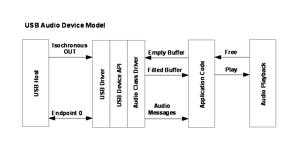
Fig. 2 USB Audio Device
Handling Audio Playback
The audio playback path is handled by the application passing buffers to be filled to the USB audio class and receiving them back with audio data from the USB host controller. The USB audio class only holds one buffer at a time and returns it to the application when it is full. Because the USB audio class only holds one buffer, it is important to pass in a new buffer to the USB audio class as soon as possible once a buffer is returned to the application to prevent underflow from the USB host controller. Since most audio playback methods uses at least two buffers, one that is playing and one that is being filled, the single buffer in the USB audio class allows for minimal buffering and eliminates copying of data between buffers. When the application has an audio buffer that needs to be filled it passes it to the USB audio class using the USBAudioBufferOut() function. The USB audio class returns the buffer to the application via the audio message handler that the application provided
in the pfnHandler member of the tUSBDAudioDevice structure. As soon as the audio device is active the application can provide a buffer to the USB audio class with a call to USBAudioBufferOut(). This call only fails if the USB audio class already has a buffer, at this point the application must wait for a previous buffer to be returned with a USBD_AUDIO_EVENT_DATAOUT message. Once the USBD_AUDIO_EVENT_DATAOUT message is received, the buffer has been filled and can be played. The buffer provided may not be completely full so the application should only play the portion of the buffer indicated by the message. To prevent underflow the application should always be sure that the audio device class has an empty buffer to fill as soon as a filled buffer is returned. The USB audio class does not provide a way to stop playing audio because typically when the USB host controller stops playing audio the host simply stops providing data to the USB audio device and playback stops.
This does not result in any notification to the application other than USBD_AUDIO_EVENT_DATAOUT messages stop being received. If the application needs to stop receiving data, it can simply stop providing buffers to the USB audio class and the audio class ignores any incoming data from the USB host controller.
Handling Other Audio Messages
The USB audio class also provides a few other notification messages to the application. These are the USBD_AUDIO_EVENT_VOLUME and USBD_AUDIO_EVENT_MUTE messages which are both inform the application of volume and mute changes in the playback stream. The USBD_AUDIO_EVENT_VOLUME message returns a value that ranges from 0 - 100 in percentage for the playback volume. The USBD_AUDIO_EVENT_MUTE is either zero indicating that the playback path is not muted or 1 indicating that the playback path is muted. The application should always take care to defer any lenghty processing of messages to its non-callback routines to prevent underflow/overflow conditions from occuring.
Using the Generic Audio Device Class
To add USB Audio data playback capability to your application via the Audio Device Class Driver, take the following steps.
Add the following header files to the source file(s) which are to support USB:
#include "ti/usblib/msp432e4/usblib.h"
#include "ti/usblib/msp432e4/device/usbdevice.h"
#include "ti/usblib/msp432e4/device/usbdaudio.h"
Define the six entry string descriptor table which is used to describe various features of your new device to the host system. The following is the string table taken from the
usb_dev_audioexample application. Edit the actual strings to suit your application and take care to ensure that you also update the length field (the first byte) of each descriptor to correctly reflect the length of the string and descriptor header. The number of string descriptors you include must be (1 + (5 * num languages)) where the number of languages agrees with the list published in string descriptor 0,g_pLangDescriptor. The strings for each language must be grouped together with all the language 1 strings before all the language 2 strings and so on.
//*****************************************************************************
//
// The languages supported by this device.
//
//*****************************************************************************
const uint8_t g_pui8LangDescriptor[] =
{
    4,
    USB_DTYPE_STRING,
    USBShort(USB_LANG_EN_US)
};

//*****************************************************************************
//
// The manufacturer string.
//
//*****************************************************************************
const uint8_t g_pui8ManufacturerString[] =
{
    (17 + 1) * 2,
    USB_DTYPE_STRING,
    'T', 0, 'e', 0, 'x', 0, 'a', 0, 's', 0, ' ', 0, 'I', 0, 'n', 0, 's', 0,
    't', 0, 'r', 0, 'u', 0, 'm', 0, 'e', 0, 'n', 0, 't', 0, 's', 0,
};

//*****************************************************************************
//
// The product string.
//
//*****************************************************************************
const uint8_t g_pui8ProductString[] =
{
    (13 + 1) * 2,
    USB_DTYPE_STRING,
    'A', 0, 'u', 0, 'd', 0, 'i', 0, 'o', 0, ' ', 0, 'E', 0, 'x', 0, 'a', 0,
    'm', 0, 'p', 0, 'l', 0, 'e', 0
};

//*****************************************************************************
//
// The serial number string.
//
//*****************************************************************************
const uint8_t g_pui8SerialNumberString[] =
{
    (8 + 1) * 2,
    USB_DTYPE_STRING,
    '1', 0, '2', 0, '3', 0, '4', 0, '5', 0, '6', 0, '7', 0, '8', 0
};

//*****************************************************************************
//
// The interface description string.
//
//*****************************************************************************
const uint8_t g_pui8HIDInterfaceString[] =
{
    (15 + 1) * 2,
    USB_DTYPE_STRING,
    'A', 0, 'u', 0, 'd', 0, 'i', 0, 'o', 0, ' ', 0, 'I', 0, 'n', 0,
    't', 0, 'e', 0, 'r', 0, 'f', 0, 'a', 0, 'c', 0, 'e', 0
};

//*****************************************************************************
//
// The configuration description string.
//
//*****************************************************************************
const uint8_t g_pui8ConfigString[] =
{
    (20 + 1) * 2,
    USB_DTYPE_STRING,
    'A', 0, 'u', 0, 'd', 0, 'i', 0, 'o', 0, ' ', 0, ' ', 0, 'C', 0,
    'o', 0, 'n', 0, 'f', 0, 'i', 0, 'g', 0, 'u', 0, 'r', 0, 'a', 0,
    't', 0, 'i', 0, 'o', 0, 'n', 0
};

//*****************************************************************************
//
// The descriptor string table.
//
//*****************************************************************************
const uint8_t * const g_ppui8StringDescriptors[] =
{
    g_pui8LangDescriptor,
    g_pui8ManufacturerString,
    g_pui8ProductString,
    g_pui8SerialNumberString,
    g_pui8HIDInterfaceString,
    g_pui8ConfigString
};

#define NUM_STRING_DESCRIPTORS (sizeof(g_ppui8StringDescriptors) /            \
                                sizeof(uint8_t *))
Define a
tUSBDAudioDevicestructure and initialize all fields as required for your application.
const tUSBDAudioDevice g_sAudioDevice =
{
    //
    // The Vendor ID you have been assigned by USB-IF.
    //
    USB_VID_YOUR_VENDOR_ID,

    //
    // The product ID you have assigned for this device.
    //
    USB_PID_YOUR_PRODUCT_ID,

    //
    // The vendor string for your device (8 chars).
    //
    USB_YOUR_VENDOR_STRING,

    //
    // The product string for your device (16 chars).
    //
    USB_YOUR_PRODUCT_STRING,

    //
    // The revision string for your device (4 chars BCD).
    //
    USB_YOUR_REVISION_STRING,

    //
    // The power consumption of your device in milliamps.
    //
    POWER_CONSUMPTION_MA,

    //
    // The value to be passed to the host in the USB configuration descriptor's
    // bmAttributes field.
    //
    USB_CONF_ATTR_SELF_PWR,

    //
    // A pointer to your control callback event handler.
    //
    YourUSBAudioMessageHandler,

    //
    // A pointer to your string table.
    //
    g_ppui8StringDescriptors,

    //
    // The number of entries in your string table.
    //
    NUM_STRING_DESCRIPTORS,

    //
    // Maximum volume setting expressed as and 8.8 signed fixed point number.
    //
    VOLUME_MAX,

    //
    // Minimum volume setting expressed as and 8.8 signed fixed point number.
    //
    VOLUME_MIN,

    //
    // Minimum volume step expressed as and 8.8 signed fixed point number.
    //
    VOLUME_STEP
};
From your main initialization function call the audio device class driver initialization function to configure the USB controller and place the device on the bus.
pvDevice = USBDAudioInit(0, &g_sAudioDevice);
Assuming
pvDevicereturned is not NULL, your device is now ready to communicate with a USB host.Once the host connects, the audio message handler is sent the USB_EVENT_CONNECTED event.
Once the host is configured to use the Audio device the audio message handler is called with a USBD_AUDIO_EVENT_ACTIVE event.
Using the Audio Device Class in a Composite Device
When using the audio device class in a composite device, the configuration of the device is very similar to how it is configured as a non-composite device. Follow all of the configuration steps in the previous section with the exception of calling USBDAudioCompositeInit() instead of USBDAudioInit(). This prepares an instance of the audio device class to be enumerated as part of a composite device. The USBDAudioCompositeInit() function takes the audio device structure and a pointer to a tCompositeEntry value so that it can properly initialize the audio device and the composite entry that is passed to the USBDCompositeInit() funtion. The code example below provides an example of how to initialize an audio device to be a part of a composite device.
//
// These should be initialized with valid values for each class.
//
extern tUSBDAudioDevice g_sAudioDevice;
void *pvAudioDevice;

//
// The array of composite device entries.
//
tCompositeEntry psCompEntries[2];

//
// Allocate the device data for the top level composite device class.
//
tUSBDCompositeDevice g_sCompDevice =
{
    //
    // Texas Intruments C-Series VID.
    //
    USB_VID_TI_1CBE,

    //
    // Texas Intruments C-Series PID for composite serial device.
    //
    USB_PID_YOUR_COMPOSITE_PID,

    //
    // This is in 2mA increments so 500mA.
    //
    250,

    //
    // Bus powered device.
    //
    USB_CONF_ATTR_BUS_PWR,

    //
    // Composite event handler.
    //
    EventHandler,

    //
    // The string table.
    //
    g_pui8StringDescriptors,
    NUM_STRING_DESCRIPTORS,

    //
    // The Composite device array.
    //
    2,
    g_psCompEntries
};

//
// The OTHER_SIZES here are the sizes of the descriptor data for other classes
// that are part of the composite device.
//
#define DESCRIPTOR_DATA_SIZE    (COMPOSITE_DAUDIO_SIZE + OTHER_SIZES)
uint8_t g_pui8DescriptorData[DESCRIPTOR_DATA_SIZE];

//
// Initialize the audio device and its composite entry which is entry 0.
//
pvAudioDevice = USBDAudioCompositeInit(0, &g_sAudioDevice, &psCompEntries[0]);

//
// Initialize other devices to add to the composite device.
//

...

USBDCompositeInit(0, &g_sCompDevice, DESCRIPTOR_DATA_SIZE,
                  g_pui8DescriptorData);
All other API calls to the USB audio device class should use the value returned by USBDAudioCompositeInit() when the APIs call for a pvInstance pointer. Also when using the audio device in a composite device the COMPOSITE_DAUDIO_SIZE value should be added to the size of the g_pui8DescriptorData array as shown in the example above.
Audio Device Class Events
The audio device class driver sends the following events to the application callback functions:
USBD_AUDIO_EVENT_IDLE - Audio interface is idle.
USBD_AUDIO_EVENT_ACTIVE - Audio interface is active.
USBD_AUDIO_EVENT_DATAOUT - Audio playback buffer released.
USBD_AUDIO_EVENT_VOLUME - Audio playback volume change.
USBD_AUDIO_EVENT_MUTE - Audio mute change.
Bulk Device Class Driver
Although not offering support for a particular standard device class, the generic bulk device class driver offers a very simple method for an application to set up USB communication with a paired application running on the USB host system. The class driver offers a single bulk receive channel and a single bulk transmit channel and, when coupled with USB buffers on each channel, provides a straightforward read/write interface to the application.
The device supports a single interface containing bulk IN and bulk OUT endpoints. The configuration and interface descriptors published by the device contain vendor specific class identifiers so an application on the host has to communicate with the device using either a custom driver or a subsystem such as WinUSB or libusb-win32 on Windows to allow the device to be accessed. An example of this is provided in the usb_dev_bulk application.
This class driver is particularly useful for applications which intend passing high volumes of data via USB and where host-side application code is being developed in partnership with the device.
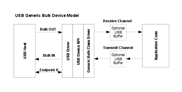
Fig. 3 USB Generic Bulk Device
The usb_dev_bulk example application makes use of this device class driver.
Bulk Device Class Events
The bulk device class driver sends the following events to the application callback functions:
Receive Channel Events
USB_EVENT_RX_AVAILABLE
USB_EVENT_ERROR
USB_EVENT_CONNECTED
USB_EVENT_DISCONNECTED
USB_EVENT_SUSPEND
USB_EVENT_RESUME
Note: The USB_EVENT_DISCONNECTED event is not be reported to the application if the MCU’s PB1/USB0VBUS pin is connected to a fixed +5 Volts rather than directly to the VBUS pin on the USB connector or if the USB controller is configured to force device mode.
Transmit Channel Events
USB_EVENT_TX_COMPLETE
Using the Generic Bulk Device Class
To add USB bulk data transmit and receive capability to your application via the Generic Bulk Device Class Driver, take the following steps.
Add the following header files to the source file(s) which are to support USB:
#include "ti/usblib/msp432e4/usblib.h"
#include "ti/usblib/msp432e4/device/usbdevice.h"
#include "ti/usblib/msp432e4/device/usbdbulk.h"
Define the 5 entry string table which is used to describe various features of your new device to the host system. The following is the string table taken from the
usb_dev_bulkexample application. Edit the actual strings to suit your application and take care to ensure that you also update the length field (the first byte) of each descriptor to correctly reflect the length of the string and descriptor header. The number of strings you include must be 5 * (number of languages listed in string descriptor 0,g_pLangDescriptor, and the strings for each language must be grouped together with all the language 1 strings before all the language 2 strings and so on.
//*****************************************************************************
//
// The languages supported by this device.
//
//*****************************************************************************
const uint8_t g_pui8LangDescriptor[] =
{
    4,
    USB_DTYPE_STRING,
    USBShort(USB_LANG_EN_US)
};

//*****************************************************************************
//
// The manufacturer string.
//
//*****************************************************************************
const uint8_t g_pui8ManufacturerString[] =
{
    (17 + 1) * 2,
    USB_DTYPE_STRING,
    'T', 0, 'e', 0, 'x', 0, 'a', 0, 's', 0, ' ', 0, 'I', 0, 'n', 0, 's', 0,
    't', 0, 'r', 0, 'u', 0, 'm', 0, 'e', 0, 'n', 0, 't', 0, 's', 0,
};

//*****************************************************************************
//
// The product string.
//
//*****************************************************************************
const uint8_t g_pui8ProductString[] =
{
    (19 + 1) * 2,
    USB_DTYPE_STRING,
    'G', 0, 'e', 0, 'n', 0, 'e', 0, 'r', 0, 'i', 0, 'c', 0, ' ', 0, 'B', 0,
    'u', 0, 'l', 0, 'k', 0, ' ', 0, 'D', 0, 'e', 0, 'v', 0, 'i', 0, 'c', 0,
    'e', 0
};

//*****************************************************************************
//
// The serial number string.
//
//*****************************************************************************
const uint8_t g_pui8SerialNumberString[] =
{
    (8 + 1) * 2,
    USB_DTYPE_STRING,
    '1', 0, '2', 0, '3', 0, '4', 0, '5', 0, '6', 0, '7', 0, '8', 0
};

//*****************************************************************************
//
// The data interface description string.
//
//*****************************************************************************
const uint8_t g_pui8DataInterfaceString[] =
{
    (19 + 1) * 2,
    USB_DTYPE_STRING,
    'B', 0, 'u', 0, 'l', 0, 'k', 0, ' ', 0, 'D', 0, 'a', 0, 't', 0,
    'a', 0, ' ', 0, 'I', 0, 'n', 0, 't', 0, 'e', 0, 'r', 0, 'f', 0,
    'a', 0, 'c', 0, 'e', 0
};

//*****************************************************************************
//
// The configuration description string.
//
//*****************************************************************************
const uint8_t g_pui8ConfigString[] =
{
    (23 + 1) * 2,
    USB_DTYPE_STRING,
    'B', 0, 'u', 0, 'l', 0, 'k', 0, ' ', 0, 'D', 0, 'a', 0, 't', 0,
    'a', 0, ' ', 0, 'C', 0, 'o', 0, 'n', 0, 'f', 0, 'i', 0, 'g', 0,
    'u', 0, 'r', 0, 'a', 0, 't', 0, 'i', 0, 'o', 0, 'n', 0
};

//*****************************************************************************
//
// The descriptor string table.
//
//*****************************************************************************
const uint8_t * const g_ppui8StringDescriptors[] =
{
    g_pui8LangDescriptor,
    g_pui8ManufacturerString,
    g_pui8ProductString,
    g_pui8SerialNumberString,
    g_pui8DataInterfaceString,
    g_pui8ConfigString
};

#define NUM_STRING_DESCRIPTORS (sizeof(g_ppui8StringDescriptors) /            \
                                sizeof(uint8_t *))
Define a
tUSBDBulkDevicestructure and initialize all fields as required for your application. The following example illustrates a simple case where no USB buffers are in use. For an example using USB buffers, see the source fileusb_bulk_structs.cin theusb_dev_bulkexample application.
const tUSBDBulkDevice g_sBulkDevice =
{
    //
    // The Vendor ID you have been assigned by USB-IF.
    //
    USB_VID_YOUR_VENDOR_ID,

    //
    // The product ID you have assigned for this device.
    //
    USB_PID_YOUR_PRODUCT_ID,

    //
    // The power consumption of your device in milliamps.
    //
    POWER_CONSUMPTION_MA,

    //
    // The value to be passed to the host in the USB configuration descriptor's
    // bmAttributes field.
    //
    USB_CONF_ATTR_SELF_PWR,

    //
    // A pointer to your receive callback event handler.
    //
    YourUSBReceiveEventCallback,

    //
    // A value that you want passed to the receive callback alongside every
    // event.
    //
    (void *)&g_sYourInstanceData,

    //
    // A pointer to your transmit callback event handler.
    //
    YourUSBTransmitEventCallback,

    //
    // A value that you want passed to the transmit callback alongside every
    // event.
    //
    (void *)&g_sYourInstanceData,

    //
    // A pointer to your string table.
    //
    g_ppui8StringDescriptors,

    //
    // The number of entries in your string table.
    //
    NUM_STRING_DESCRIPTORS
};
Add a receive event handler function, YourUSBReceiveEventCallback in the previous example, to your application taking care to handle all messages which require a particular response. For the generic bulk device class, only the USB_EVENT_RX_AVAILABLE MUST be handled by the receive event handler. In response to USB_EVENT_RX_AVAILABLE, your handler should check the amount of data received by calling
USBDBulkRxPacketAvailable()then read it using a call toUSBDBulkPacketRead(). This causes the newly received data to be acknowledged to the host and instructs the host that it may now transmit another packet. If you are unable to read the data immediately, return 0 from the callback handler and you are called back once again a few milliseconds later. Although no other events must be handled, USB_EVENT_CONNECTED and USB_EVENT_DISCONNECTED is typically required since these indicate when a host connects or disconnects and allow the application to flush any buffers or reset state as required. Attempts to send data when the host is disconnected result in an immediate failure.Add a transmit event handler function, YourUSBTransmitEventCallback in the previous example, to your application taking care to handle all messages which require a particular response. For the generic bulk device class, there are no events sent to the transmit callback which MUST be handled but applications usually want to note USB_EVENT_TX_COMPLETE since this is an interlock message indicating that the previous packet sent has been acknowledged by the host and a new packet can now be sent.
From your main initialization function call the generic bulk device class driver initialization function to configure the USB controller and place the device on the bus.
pvDevice = USBDBulkInit(0, &g_sBulkDevice);
Assuming
pvDevicereturned is not NULL, your device is now ready to communicate with a USB host.Once the host connects, your receive event handler is sent USB_EVENT_CONNECTED and the first packet of data may be sent to the host using
USBDBulkPacketWrite()with following packets transmitted as soon as USB_EVENT_TX_COMPLETE is received.
Using the Bulk Device Class in a Composite Device
When using the bulk device class in a composite device, the configuration of the device is very similar to how it is configured as a non-composite device. Follow all of the configuration steps in the previous section with the exception of calling USBDBulkCompositeInit() instead of USBDBulkInit(). This prepares an instance of the bulk device class to be enumerated as part of a composite device. The USBDBulkCompositeInit() function takes the bulk device structure and a pointer to a tCompositeEntry value so that it can properly initialize the bulk device and the composite entry that is passed to the USBDCompositeInit() funtion. The code example below provides an example of how to initialize a bulk device to be a part of a composite device.
//
// These should be initialized with valid values for each class.
//
extern tUSBDBulkDevice g_sBulkDevice;
void *pvBulkDevice;

//
// The array of composite devices.
//
tCompositeEntry psCompEntries[2];

//
// Allocate the device data for the top level composite device class.
//
tUSBDCompositeDevice g_sCompDevice =
{
    //
    // Texas Intruments C-Series VID.
    //
    USB_VID_TI_1CBE,

    //
    // Texas Intruments C-Series PID for composite serial device.
    //
    USB_PID_YOUR_COMPOSITE_PID,

    //
    // This is in 2mA increments so 500mA.
    //
    250,

    //
    // Bus powered device.
    //
    USB_CONF_ATTR_BUS_PWR,

    //
    // Composite event handler.
    //
    EventHandler,

    //
    // The string table.
    //
    g_pui8StringDescriptors,
    NUM_STRING_DESCRIPTORS,

    //
    // The Composite device array.
    //
    2,
    g_psCompEntries
};

//
// The OTHER_SIZES here are the sizes of the descriptor data for other classes
// that are part of the composite device.
//
#define DESCRIPTOR_DATA_SIZE    (COMPOSITE_DBULK_SIZE + OTHER_SIZES)
uint8_t g_pui8DescriptorData[DESCRIPTOR_DATA_SIZE];

//
// Initialize the bulk device and its composite entry.
//
pvBulkDevice = USBDBulkCompositeInit(0, &g_sBulkDevice, &psCompEntries[0]);

//
// Initialize other devices to add to the composite device.
//

...

//
// Initialize the USB controller as a composite device.
//
USBDCompositeInit(0, &g_sCompDevice, DESCRIPTOR_DATA_SIZE,
                  g_pui8DescriptorData);
All other API calls to the USB bulk device class should use the value returned by USBDBulkCompositeInit() when the API calls for a pvInstance pointer. Also when using the bulk device in a composite device the COMPOSITE_DBULK_SIZE value should be added to the size of the g_pui8DescriptorData array as shown in the example above.
Windows Drivers for Generic Bulk Devices
Since generic bulk devices appear to a host operating system as vendor-specific devices, no device drivers on the host system is able to communicate with them without some help from the device developer. This help may involve writing a specific Windows kernel driver for the device or, if kernel driver programming is too daunting, steering Windows to use one of several possible generic kernel drivers that can manage the device on behalf of a user mode application.
Using this second model, a device developer need not write any Windows driver code but would need to write an application or DLL that interfaces with the device via the user-mode API offered by whichever USB subsystem they chose to manage their device. The developer is also responsible for producing a suitable INF file to allow Windows to associate the device (identified via its VID/PID combination) with a particular driver.
A least two suitable USB subsystems are available for Windows - WinUSB from Microsoft or open-source project libusb-win32 available from SourceForge.
WinUSB supports WindowsXP, Windows Vista and Windows7 systems. Further information can be obtained from MSDN at https://msdn.microsoft.com/en-us/library/aa476426.aspx. To develop applications using the WinUSB interface, the Windows Driver Development Kit (DDK) must be installed on your build PC.
libusb-win32 supports Windows98SE, Windows2000, WindowsNT and WindowsXP and can be downloaded from https://libusb-win32.sourceforge.net/. It offers a straightforward method of accessing the device and also provides a very helpful INF file generator.
Sample WinUSB INF file
This file illustrates how to build an INF to associate your device with the WinUSB subsystem on WindowsXP or Vista. Note that the driver package for the device must include not only this INF file but the Microsoft-supplied coinstallers listed in the files section. These can be found within the Windows Driver Development Kit (DDK).
; -----------------------------------------------------------------------------
;
; USBLib Generic Bulk USB device driver installer
;
; This INF file may be used as a template when creating customized applications
; based on the USBLib generic bulk devices. Areas of the file requiring
; customization for a new device are commented with NOTEs.
;
; -----------------------------------------------------------------------------

; NOTE: When you customize this INF for your own device, create a new class
; name (Class) and a new GUID (ClassGuid). GUIDs may be created using the
; guidgen tool from Windows Visual Studio.

[Version]
Signature = "$Windows NT$"
Class = USBLibBulkDeviceClass
ClassGuid={F5450C06-EB58-420e-8F98-A76C5D4AFB18}
Provider = %ProviderName%
CatalogFile=MyCatFile.cat

; ========== Manufacturer/Models sections ===========

[Manufacturer]
%ProviderName% = USBLibBulkDevice_WinUSB,NTx86,NTamd64

; NOTE: Replace the VID and PID in the following two sections with the
; correct values for your device.

[USBLibBulkDevice_WinUSB.NTx86]
%USB\USBLibBulkDevice.DeviceDesc% =USB_Install, USB\VID_1CBE&PID_0003

[USBLibBulkDevice_WinUSB.NTamd64]
%USB\USBLibBulkDevice.DeviceDesc% =USB_Install, USB\VID_1CBE&PID_0003

; =================== Installation ===================

[ClassInstall32]
AddReg=AddReg_ClassInstall

[AddReg_ClassInstall]
HKR,,,,"%DeviceClassDisplayName%"
HKR,,Icon,,"-20"

[USB_Install]
Include=winusb.inf
Needs=WINUSB.NT

[USB_Install.Services]
Include=winusb.inf
AddService=WinUSB,0x00000002,WinUSB_ServiceInstall

[WinUSB_ServiceInstall]
DisplayName     = %WinUSB_SvcDesc%
ServiceType     = 1
StartType       = 3
ErrorControl    = 1
ServiceBinary   = %12%\WinUSB.sys

[USB_Install.Wdf]
KmdfService=WINUSB, WinUsb_Install

[WinUSB_Install]
KmdfLibraryVersion=1.5

[USB_Install.HW]
AddReg=Dev_AddReg

; NOTE: Create a new GUID for your interface and replace the following one
; when customizing for a new device.

[Dev_AddReg]
HKR,,DeviceInterfaceGUIDs,0x10000,"{6E45736A-2B1B-4078-B772-B3AF2B6FDE1C}"

[USB_Install.CoInstallers]
AddReg=CoInstallers_AddReg
CopyFiles=CoInstallers_CopyFiles

[CoInstallers_AddReg]
HKR,,CoInstallers32,0x00010000,"WdfCoInstaller01005.dll,WdfCoInstaller","WinUSBCoInstaller.dll"

[CoInstallers_CopyFiles]
WinUSBCoInstaller.dll
WdfCoInstaller01005.dll

[DestinationDirs]
CoInstallers_CopyFiles=11

; ================= Source Media Section =====================

[SourceDisksNames]
1 = %DISK_NAME%,,,\i386
2 = %DISK_NAME%,,,\amd64

[SourceDisksFiles.x86]
WinUSBCoInstaller.dll=1
WdfCoInstaller01005.dll=1

[SourceDisksFiles.amd64]
WinUSBCoInstaller.dll=2
WdfCoInstaller01005.dll=2

; =================== Strings ===================

; Note: Replace these as appropriate to describe your device.

[Strings]
ProviderName="Texas Instruments"
USB\USBLibBulkDevice.DeviceDesc="Generic Bulk Device"
WinUSB_SvcDesc="WinUSB"
DISK_NAME="USBLib Install Disk"
DeviceClassDisplayName="USBLib Bulk Devices"
Sample libusb-win32 INF File
The following is an example of an INF file that can be used to associate the usb_dev_bulk example device with the libusb-win32 subsystem on Windows systems and to install the necessary drivers. This was created using the “INF Wizard” application which is included in the libusb-win32 download package.
[Version]
Signature = "$Chicago$"
provider  = %manufacturer%
DriverVer = 03/20/2007,0.1.12.1
CatalogFile = usb_dev_bulk_libusb.cat
CatalogFile.NT = usb_dev_bulk_libusb.cat
CatalogFile.NTAMD64 = usb_dev_bulk_libusb_x64.cat

Class = LibUsbDevices
ClassGUID = {EB781AAF-9C70-4523-A5DF-642A87ECA567}

[ClassInstall]
AddReg=libusb_class_install_add_reg

[ClassInstall32]
AddReg=libusb_class_install_add_reg

[libusb_class_install_add_reg]
HKR,,,,"LibUSB-Win32 Devices"
HKR,,Icon,,"-20"

[Manufacturer]
%manufacturer%=Devices,NT,NTAMD64

;--------------------------------------------------------------------------
; Files
;--------------------------------------------------------------------------

[SourceDisksNames]
1 = "Libusb-Win32 Driver Installation Disk",,

[SourceDisksFiles]
libusb0.sys = 1,,
libusb0.dll = 1,,
libusb0_x64.sys = 1,,
libusb0_x64.dll = 1,,

[DestinationDirs]
libusb_files_sys = 10,system32\drivers
libusb_files_sys_x64 = 10,system32\drivers
libusb_files_dll = 10,system32
libusb_files_dll_wow64 = 10,syswow64
libusb_files_dll_x64 = 10,system32

[libusb_files_sys]
libusb0.sys

[libusb_files_sys_x64]
libusb0.sys,libusb0_x64.sys

[libusb_files_dll]
libusb0.dll

[libusb_files_dll_wow64]
libusb0.dll

[libusb_files_dll_x64]
libusb0.dll,libusb0_x64.dll

;--------------------------------------------------------------------------
; Device driver
;--------------------------------------------------------------------------

[LIBUSB_DEV]
CopyFiles = libusb_files_sys, libusb_files_dll
AddReg    = libusb_add_reg

[LIBUSB_DEV.NT]
CopyFiles = libusb_files_sys, libusb_files_dll

[LIBUSB_DEV.NTAMD64]
CopyFiles = libusb_files_sys_x64, libusb_files_dll_wow64, libusb_files_dll_x64

[LIBUSB_DEV.HW]
DelReg = libusb_del_reg_hw
AddReg = libusb_add_reg_hw

[LIBUSB_DEV.NT.HW]
DelReg = libusb_del_reg_hw
AddReg = libusb_add_reg_hw

[LIBUSB_DEV.NTAMD64.HW]
DelReg = libusb_del_reg_hw
AddReg = libusb_add_reg_hw

[LIBUSB_DEV.NT.Services]
AddService = libusb0, 0x00000002, libusb_add_service

[LIBUSB_DEV.NTAMD64.Services]
AddService = libusb0, 0x00000002, libusb_add_service

[libusb_add_reg]
HKR,,DevLoader,,*ntkern
HKR,,NTMPDriver,,libusb0.sys

; Older versions of this .inf file installed filter drivers. They are not
; needed any more and must be removed
[libusb_del_reg_hw]
HKR,,LowerFilters
HKR,,UpperFilters

; Device properties
[libusb_add_reg_hw]
HKR,,SurpriseRemovalOK, 0x00010001, 1

;--------------------------------------------------------------------------
; Services
;--------------------------------------------------------------------------

[libusb_add_service]
DisplayName    = "LibUsb-Win32 - Kernel Driver 03/20/2007, 0.1.12.1"
ServiceType    = 1
StartType      = 3
ErrorControl   = 0
ServiceBinary  = %12%\libusb0.sys

;--------------------------------------------------------------------------
; Devices
;--------------------------------------------------------------------------

[Devices]
"Generic Bulk Device"=LIBUSB_DEV, USB\VID_1cbe&PID_0003

[Devices.NT]
"Generic Bulk Device"=LIBUSB_DEV, USB\VID_1cbe&PID_0003

[Devices.NTAMD64]
"Generic Bulk Device"=LIBUSB_DEV, USB\VID_1cbe&PID_0003


;--------------------------------------------------------------------------
; Strings
;--------------------------------------------------------------------------

[Strings]
manufacturer = "Texas Instruments"
CDC Device Class Driver
The USB Communication Device Class (CDC) class driver supports the CDC Abstract Control Model variant and allows a client application to be seen as a virtual serial port to the USB host system. The driver provides two channels, one transmit and one receive. The channels may be used in conjunction with USB buffers to provide a simple read/write interface for data transfer to and from the host. Additional APIs and events are used to support serial-link-specific operations such as notification of UART errors, sending break conditions and setting communication line parameters.
The data transmission capabilities of this device class driver are very similar to the generic bulk class but, since this is a standard device class, the host operating system is likely able to access the device without the need for any special additional device drivers. On Windows, for example, a simple INF file is all that is required to make the USB device appear as a COM port which can be accessed by any serial terminal application.
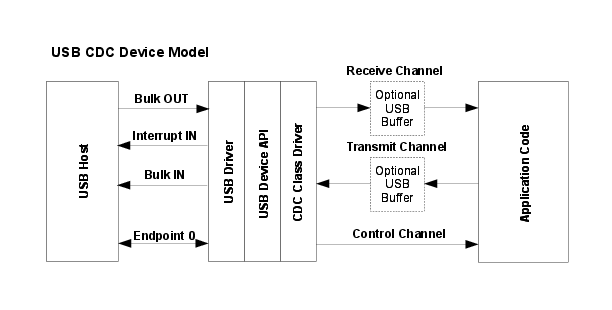
Fig. 4 USB CDC Device
This device class uses three endpoints in addition to endpoint zero. Two bulk endpoints carry data to and from the host and an interrupt IN endpoint is used to signal any serial errors such as break, framing error or parity error detected by the device. Endpoint zero carries standard USB requests and also CDC-specific requests which translate to events passed to the application via the control channel callback.
The usb_dev_serial example application makes use of this device class driver.
CDC Device Class Events
The CDC device class driver sends the following events to the application callback functions:
Receive Channel Events
USB_EVENT_RX_AVAILABLE
USB_EVENT_DATA_REMAINING
USB_EVENT_ERROR
Transmit Channel Events
USB_EVENT_TX_COMPLETE
Control Channel Events
USB_EVENT_CONNECTED
USB_EVENT_DISCONNECTED
USB_EVENT_SUSPEND
USB_EVENT_RESUME
USBD_CDC_EVENT_SEND_BREAK
USBD_CDC_EVENT_CLEAR_BREAK
USBD_CDC_EVENT_SET_LINE_CODING
USBD_CDC_EVENT_GET_LINE_CODING
USBD_CDC_EVENT_SET_CONTROL_LINE_STATE
Note: The USB_EVENT_DISCONNECTED event is not reported to the application if the MCU’s PB1/USB0VBUS pin is connected to a fixed +5 Volts rather than directly to the VBUS pin on the USB connector or if the USB controller is configured to force device mode.
Using the CDC Device Class Driver
To add USB CDC data transmit and receive capability to your application via the CDC Device Class Driver, take the following steps.
Add the following header files to the source file(s) which are to support USB:
#include "ti/usblib/msp432e4/usblib.h"
#include "ti/usblib/msp432e4/device/usbdevice.h"
#include "ti/usblib/msp432e4/device/usbdcdc.h"
Define the 6 entry string descriptor table which is used to describe various features of your new device to the host system. The following is the string table taken from the
usb_dev_serialexample application. Edit the actual strings to suit your application and take care to ensure that you also update the length field (the first byte) of each descriptor to correctly reflect the length of the string and descriptor header. The number of string descriptors you include must be (1 + (5 * num languages)) where the number of languages agrees with the list published in string descriptor 0,g_pLangDescriptor. The strings for each language must be grouped together with all the language 1 strings before all the language 2 strings and so on.
//*****************************************************************************
//
// The languages supported by this device.
//
//*****************************************************************************
const uint8_t g_pui8LangDescriptor[] =
{
    4,
    USB_DTYPE_STRING,
    USBShort(USB_LANG_EN_US)
};

//*****************************************************************************
//
// The manufacturer string.
//
//*****************************************************************************
const uint8_t g_pui8ManufacturerString[] =
{
    (17 + 1) * 2,
    USB_DTYPE_STRING,
    'T', 0, 'e', 0, 'x', 0, 'a', 0, 's', 0, ' ', 0, 'I', 0, 'n', 0, 's', 0,
    't', 0, 'r', 0, 'u', 0, 'm', 0, 'e', 0, 'n', 0, 't', 0, 's', 0,
};

//*****************************************************************************
//
// The product string.
//
//*****************************************************************************
const uint8_t g_pui8ProductString[] =
{
    2 + (16 * 2),
    USB_DTYPE_STRING,
    'V', 0, 'i', 0, 'r', 0, 't', 0, 'u', 0, 'a', 0, 'l', 0, ' ', 0,
    'C', 0, 'O', 0, 'M', 0, ' ', 0, 'P', 0, 'o', 0, 'r', 0, 't', 0
};

//*****************************************************************************
//
// The serial number string.
//
//*****************************************************************************
const uint8_t g_pui8SerialNumberString[] =
{
    2 + (8 * 2),
    USB_DTYPE_STRING,
    '1', 0, '2', 0, '3', 0, '4', 0, '5', 0, '6', 0, '7', 0, '8', 0
};

//*****************************************************************************
//
// The control interface description string.
//
//*****************************************************************************
const uint8_t g_pui8ControlInterfaceString[] =
{
    2 + (21 * 2),
    USB_DTYPE_STRING,
    'A', 0, 'C', 0, 'M', 0, ' ', 0, 'C', 0, 'o', 0, 'n', 0, 't', 0,
    'r', 0, 'o', 0, 'l', 0, ' ', 0, 'I', 0, 'n', 0, 't', 0, 'e', 0,
    'r', 0, 'f', 0, 'a', 0, 'c', 0, 'e', 0
};

//*****************************************************************************
//
// The configuration description string.
//
//*****************************************************************************
const uint8_t g_pui8ConfigString[] =
{
    2 + (26 * 2),
    USB_DTYPE_STRING,
    'S', 0, 'e', 0, 'l', 0, 'f', 0, ' ', 0, 'P', 0, 'o', 0, 'w', 0,
    'e', 0, 'r', 0, 'e', 0, 'd', 0, ' ', 0, 'C', 0, 'o', 0, 'n', 0,
    'f', 0, 'i', 0, 'g', 0, 'u', 0, 'r', 0, 'a', 0, 't', 0, 'i', 0,
    'o', 0, 'n', 0
};

//*****************************************************************************
//
// The descriptor string table.
//
//*****************************************************************************
const uint8_t * const g_ppui8StringDescriptors[] =
{
    g_pui8LangDescriptor,
    g_pui8ManufacturerString,
    g_pui8ProductString,
    g_pui8SerialNumberString,
    g_pui8ControlInterfaceString,
    g_pui8ConfigString
};

#define NUM_STRING_DESCRIPTORS (sizeof(g_ppui8StringDescriptors) /            \
                                sizeof(uint8_t *))
Define a
tUSBDCDCDevicestructure and initialize all fields as required for your application. The following example illustrates a simple case where no USB buffers are in use. For an example using USB buffers, see the source fileusb_bulk_structs.cin theusb_dev_serialexample application.
const tUSBDCDCDevice g_sCDCDevice =
{
    //
    // The Vendor ID you have been assigned by USB-IF.
    //
    USB_VID_YOUR_VENDOR_ID,

    //
    // The product ID you have assigned for this device.
    //
    USB_PID_YOUR_PRODUCT_ID,

    //
    // The power consumption of your device in milliamps.
    //
    POWER_CONSUMPTION_MA,

    //
    // The value to be passed to the host in the USB configuration descriptor's
    // bmAttributes field.
    //
    USB_CONF_ATTR_SELF_PWR,

    //
    // A pointer to your control callback event handler.
    //
    YourUSBControlEventCallback,

    //
    // A value that you want passed to the control callback alongside every
    // event.
    //
    (void *)&g_sYourInstanceData,

    //
    // A pointer to your receive callback event handler.
    //
    YourUSBReceiveEventCallback,

    //
    // A value that you want passed to the receive callback alongside every
    // event.
    //
    (void *)&g_sYourInstanceData,

    //
    // A pointer to your transmit callback event handler.
    //
    YourUSBTransmitEventCallback,

    //
    // A value that you want passed to the transmit callback alongside every
    // event.
    //
    (void *)&g_sYourInstanceData,

    //
    // A pointer to your string table.
    //
    g_ppui8StringDescriptors,

    //
    // The number of entries in your string table.
    //
    NUM_STRING_DESCRIPTORS
};
Add a receive event handler function, YourUSBReceiveEventCallback in the previous example, to your application taking care to handle all messages which require a particular response. For the CDC device class, USB_EVENT_RX_AVAILABLE and USB_EVENT_DATA_REMAINING MUST be handled by the receive event handler. In response to USB_EVENT_RX_AVAILABLE, your handler should check the amount of data received by calling
USBDCDCRxPacketAvailable()then read it using a call toUSBDCDCPacketRead(). This causes the newly received data to be acknowledged to the host and instructs the host that it may now transmit another packet. If you are unable to read the data immediately, return 0 from the callback handler and you is called back once again a few milliseconds later. On USB_EVENT_DATA_REMAINING the application should return the number of bytes of data it currently has buffered. This event controls timing of some incoming requests to, for example, send break conditions or change line transmission parameters. These requests are held off until all previously received data has been processed so it is important to ensure that this event returns 0 only once any application buffers are empty. Although no other events must be handled, USB_EVENT_CONNECTED and USB_EVENT_DISCONNECTED is typically required since these indicate when a host connects or disconnects and allow the application to flush any buffers or reset state as required. Attempts to send data when the host is disconnected result in an immediate failure.Add a transmit event handler function, YourUSBTransmitEventCallback in the previous example, to your application taking care to handle all messages which require a particular response. For the CDC device class, there are no events sent to the transmit callback which MUST be handled but applications usually want to note USB_EVENT_TX_COMPLETE since this is an interlock message indicating that the previous packet sent has been acknowledged by the host and a new packet can now be sent.
Add a control event handler function, YourUSBControlEventCallback in the previous example, to your application and ensure that you handle USBD_CDC_EVENT_GET_LINE_CODING, returning a valid line coding configuration even if your device is not actually driving a UART. Handle the other control events as required for your application.
From your main initialization function call the CDC device class driver initialization function to configure the USB controller and place the device on the bus.
pvDevice = USBDCDCInit(0, &g_sCDCDevice);
Assuming
pvDevicereturned is not NULL, your device is now ready to communicate with a USB host.Once the host connects, your control event handler is sent USB_EVENT_CONNECTED and the first packet of data may be sent to the host using
USBDCDCPacketWrite()with following packets transmitted as soon as USB_EVENT_TX_COMPLETE is received via the transmit event handler.
Using the Composite CDC Serial Device Class
When using the CDC serial device class in a composite, the configuration of the device is very similar to how it is configured as a non-composite device. Follow all of the configuration steps in the previous section with the exception of calling USBDCDCCompositeInit() instead of USBDCDCInit(). This prepares an instance of the CDC serial device class to be enumerated as part of a composite device. The USBDCDCCompositeInit() function takes the CDC serial device structure and a pointer to a tCompositeEntry value so that it can properly initialize the CDC serial device and the composite entry that is passed to the USBDCompositeInit() funtion. The code example below provides an example of how to initialize an CDC serial device to be a part of a composite device.
//
// These should be initialized with valid values for each class.
//
extern tUSBDCDCDevice g_sCDCDevice;
void *pvCDCDevice;

//
// The array of composited devices.
//
tCompositeEntry psCompEntries[2];

//
// Allocate the device data for the top level composite device class.
//
tUSBDCompositeDevice g_sCompDevice =
{
    //
    // Texas Intruments C-Series VID.
    //
    USB_VID_TI_1CBE,

    //
    // Texas Intruments C-Series PID for composite serial device.
    //
    USB_PID_YOUR_COMPOSITE_PID,

    //
    // This is in 2mA increments so 500mA.
    //
    250,

    //
    // Bus powered device.
    //
    USB_CONF_ATTR_BUS_PWR,

    //
    // Composite event handler.
    //
    EventHandler,

    //
    // The string table.
    //
    g_pui8StringDescriptors,
    NUM_STRING_DESCRIPTORS,

    //
    // The Composite device array.
    //
    2,
    g_psCompEntries
};

//
// The OTHER_SIZES here are the sizes of the descriptor data for other classes
// that are part of the composite device.
//
#define DESCRIPTOR_DATA_SIZE    (COMPOSITE_DCDC_SIZE + OTHER_SIZES)
uint8_t g_pui8DescriptorData[DESCRIPTOR_DATA_SIZE];

//
// Save the instance data for this CDC serial device.
//
pvCDCDevice = USBDCDCCompositeInit(0, &g_sCDCDevice, &psCompEntries[0]);

...

//
// Initialize the USB controller as a composite device.
//
USBDCompositeInit(0, &g_sCompDevice, DESCRIPTOR_DATA_SIZE,
                      g_pui8DescriptorData);
All other API calls to the USB CDC serial device class should use the value returned by USBDCDCCompositeInit() when the API calls for a pvInstance pointer. Also when using the CDC serial device in a composite device the COMPOSITE_DCDC_SIZE value should be added to the size of the g_pui8DescriptorData array as shown in the example above.
Windows Drivers for CDC Serial Devices
Making your CDC serial) device visible as a virtual COM port on a Windows system is very straightforward since Windows already includes a device driver supporting USB CDC devices. The device developer must merely provide a single INF file to associate the VID and PID of the new device with the Windows USB CDC driver, usbser.sys. When using the serial device in a composite device it is important to remember to append &MI_xx value to the VID/PID entry as shown in the example below. The actual number used with the MI_* value is the interface number assigned to the serial device. An example INF file is provided below. Unlike the case for the generic bulk device class, no additional installation files are necessary since the CDC serial driver is already installed by default and does not, therefore, have to be redistributed by the device developer.
;
;   Texas Instruments USBLib USB CDC (serial) driver installation file.
;
[Version]
Signature="$Windows NT$"
Class=Ports
ClassGuid={4D36E978-E325-11CE-BFC1-08002BE10318}
Provider=%MFGNAME%
LayoutFile=layout.inf
DriverVer=08/17/2001,5.1.2600.0

[Manufacturer]
%MFGNAME%=DeviceList

[DestinationDirs]
DefaultDestDir=12

[SourceDisksFiles]

[SourceDisksNames]

;
; NOTE: Change the VID and PID in the following section to match your device.
; The values with the &MI_xx values are for the composite serial devices
; examples.
;

[DeviceList]
;
; This entry is for the single serial port example usb_dev_serial.
;
%DESCRIPTION_0%=DriverInstall,USB\VID_1CBE&PID_0002

;
; These entries are for the dual serial port composite example usb_dev_cserial.
;
%DESCRIPTION_0%=DriverInstall,USB\VID_1CBE&PID_0007&MI_00
%DESCRIPTION_1%=DriverInstall,USB\VID_1CBE&PID_0007&MI_01

;
; This entry is for the composite hid/serial device usb_dev_chidcdc.  Notice
; that the value is MI_01 because the serial device is on interface 1.
;
%DESCRIPTION_1%=DriverInstall,USB\VID_1CBE&PID_0009&MI_01

;------------------------------------------------------------------------------
;  Windows XP/2000 Sections
;------------------------------------------------------------------------------

[DriverInstall.nt]
CopyFiles=DriverCopyFiles
AddReg=DriverInstall.nt.AddReg

[DriverCopyFiles]
usbser.sys,,,0x20

[DriverInstall.nt.AddReg]
HKR,,DevLoader,,*ntkern
HKR,,NTMPDriver,,usbser.sys
HKR,,EnumPropPages32,,"MsPorts.dll,SerialPortPropPageProvider"

[DriverInstall.nt.Services]
AddService=usbser, 0x00000002, DriverService

[DriverService]
DisplayName=%SERVICE%
ServiceType=1
StartType=3
ErrorControl=1
ServiceBinary=%12%\usbser.sys

;------------------------------------------------------------------------------
;  String Definitions (change for your device)
;------------------------------------------------------------------------------

[Strings]
MFGNAME       = "Texas Instruments"
DESCRIPTION_0 = "USB Serial Port"
DESCRIPTION_1 = "USB Serial Command Port"
SERVICE       = "USB CDC serial port"
Composite Device Class Driver
The USB composite device class allows classes that are already defined in the USB library to be combined into a single composite device. The device configuration descriptors for the included device classes are merged at run time and returned to the USB host controller during device enumeration as a single composite USB device. Since each device class requires some unique initialization, the device classes provide a separate initialization API that does not touch the USB controller but does perform all other initialization. The initialization of the USB controller is deferred until the USB composite device is initialized and has merged the multiple device configuration descriptors into a single configuration descriptor so that it can properly initialize the USB controller. The endpoint numbers, interface numbers, and string indexes that are included in the device configuration descriptors are modified by the USB composite device class so that the values are valid in the composite device configuration descriptor.
Defining a Composite Device
The USB composite device class is defined at the top level in the tUSBDCompositeDevice structure which is used to describe the class to the USB library. In order for the USB composite device to enumerate and function properly, all members of this structure must be filled with valid information. The usVID and usPID values should have valid Vendor ID and Product ID values for the composite device. The power requirements for the device as specified in the usMaxPowermA and ucPwrAttributes and should take into account the power requirements and settings for all devices classes that the composite device is using. The only truly optional member of the tUSBDCompositeDevice structure is the pfnCallback function which provides notifications to the application that are not handled by the individual device classes. The device specific strings should be included in the ppui8StringDescriptors and ui32NumStringDescriptors members. This list of strings should include the following three
strings in the following order: Manufacturer, Product, and Product serial number. All other strings used by the classes are specified and are sourced from the included device classes. The psPrivateData should be set to point to a tCompositeInstance structure which provides the composite class with memory for its instance data.
Note: It is important to insure that the microcontroller has enough endpoints to satisfy the number of devices included in the composite class.
uint32_t g_pui32CompWorkspace[NUM_DEVICES];

tUSBDCompositeDevice g_sCompDevice =
{
    //
    // Vendor ID.
    //
    VENDOR_ID,

    //
    // Product ID.
    //
    VENDOR_PRODUCT_ID,

    //
    // This is in 2mA increments or 500mA.
    //
    250,

    //
    // Bus powered device.
    //
    USB_CONF_ATTR_BUS_PWR,

    //
    // Generic USB handler for the composite device.
    //
    CompositeHandler,

    //
    // The string table.
    //
    g_pStringDescriptors,
    NUM_STRING_DESCRIPTORS,

    //
    // The number of device classes in the composite entry array.
    //
    NUM_DEVICES,
    g_psCompDevices
};
Allocating Memory
The USB composite device class requires three different types of memory allocated to properly enumerate and function with the included device classes. The main allocation is a block of memory that is used to build up the combined device configuration descriptor for the combination of the desired device classes. The individual device classes provides a size in a __COMPOSITE_*_SIZE__ macro that indicates the size in bytes required to hold the configuration descriptor for the device class. This allows the application to provide a large enough buffer to the USBDCompositeInit() function for merging the device descriptors.
Defining Device Class Instances
When defining a composite device the application must determine the size of the buffer that is passed into the USBDCompositeInit() function. For example, if a composite device is made up of two serial devices then a buffer of size (COMPOSITE_DCDC_SIZE * 2) should be passed into the initialization routine and an array of that size should be declared in the application.
uint8_t pucDesciptorData[COMPOSITE_DCDC_SIZE*2];
The application must also allocate separate serial device structure for each instance of the devices that are included in a composite device. This is true even when including two devices classes of the same type are added so that the instances can be differentiated by the USB library. The USB composite device class can determine which instance to use based on the interface number that is accessed by the host controller. The application initializes the data in the array of tCompositeEntry structures passed into the composite initialization for the class.
extern tUSBDCDCDevice g_sCDCDeviceA;
extern tUSBDCDCDevice g_sCDCDeviceB;

tCompositeEntry g_psDevices[2];
Interface Handling
The device class interfaces are merged into the composite device descriptor and the composite class modifies the default interface assignments to insure monotonically increasing indexes for all of the included interfaces. In the example above for the two serial ports, the first serial device would be interface 0 and the second would enumerate as interface 1.
String Handling
The device class strings are merged into the composite device descriptor which requires that the composite class modify the default string indexes. In doing this it always ignores the three default string indexes in the device descriptor. The remaining string indexes are modified to match in the configuration descriptor.
Example Composite Device
This section continues with the example above that used two USB device serial classes in a single device. This includes more detailed examples and code that demonstrate the configuration and setup needed for a composite serial device.
Composite Device Instance
The application must first allocate two serial device structures and pass them into the composite initialization function for the USB serial CDC device. The allocation and initialization are shown below:
//
// Buffers for serial device A.
//
const tUSBBuffer g_sTxBufferA;
const tUSBBuffer g_sRxBufferA;

//
// Buffers for serial device B.
//
const tUSBBuffer g_sTxBufferB;
const tUSBBuffer g_sRxBufferB;

//
// Device description for Serial Device A.
//
const tUSBDCDCDevice g_sCDCDeviceA =
{
    USB_VID_TI_1CBE,
    USB_PID_SERIAL,
    0,
    USB_CONF_ATTR_SELF_PWR,
    ControlHandler,
    (void *)&g_sCDCDeviceA,
    USBBufferEventCallback,
    (void *)&g_sRxBufferA,
    USBBufferEventCallback,
    (void *)&g_sTxBufferA,
    0,
    0
};

//
// Device description for Serial Device B.
//
const tUSBDCDCDevice g_sCDCDeviceB =
{
    USB_VID_TI_1CBE,
    USB_PID_SERIAL,
    0,
    USB_CONF_ATTR_SELF_PWR,
    ControlHandler,
    (void *)&g_sCDCDeviceB,
    USBBufferEventCallback,
    (void *)&g_sRxBufferB,
    USBBufferEventCallback,
    (void *)&g_sTxBufferB,
    0,
    0
};
Now the application must allocate the device array so that it is provided to the USB composite device class. The following code shows the allocation of the composite device array that holds the data for the two serial devices.
tCompositeEntry g_psDevices[2];
Once the array of devices has been allocated, this array is included in the USB composite device structure when the device structure is allocated and initialized. The code below shows this allocation:
//
// Initialize the USB composite device structure.
//
tUSBDCompositeDevice g_sCompDevice =
{
    //
    // TI USBLib VID.
    //
    USB_VID_TI_1CBE,

    //
    // PID for the composite serial device.
    //
    USB_PID_COMP_SERIAL,

    //
    // This is in 2mA increments so 500mA.
    //
    250,

    //
    // Bus powered device.
    //
    USB_CONF_ATTR_BUS_PWR,

    //
    // Generic USB handler for the composite device.
    //
    CompositeHandler,

    //
    // The string table.
    //
    g_pStringDescriptors,
    NUM_STRING_DESCRIPTORS,

    //
    // Include the array of composite devices.
    //
    NUM_DEVICES,
    g_psCompDevices
};
The last bit of memory that needs to be allocated is the USB composite device descriptor workspace which is provided at Initialization time. The allocation for two serial devices is shown below:
uint8_t pucDesciptorData[COMPOSITE_DCDC_SIZE*2];
Once all of the memory has been initialized and the appropriate memory allocated, the application must call the initialization functions for each device instance. In the case of the serial ports, the USB buffers used must also first be initialized before completing initialization.
//
// Initialize the transmit and receive buffers.
//
USBBufferInit((tUSBBuffer *)&g_sTxBufferA);
USBBufferInit((tUSBBuffer *)&g_sRxBufferA);
USBBufferInit((tUSBBuffer *)&g_sTxBufferB);
USBBufferInit((tUSBBuffer *)&g_sRxBufferB);

//
// Initialize the two serial port instances that are part of this composite
// device.
//
pvSerialDeviceA =
    USBDCDCCompositeInit(0, &g_sCDCDeviceA, &g_psCompDevices[0]);
pvSerialDeviceB =
    USBDCDCCompositeInit(0, &g_sCDCDeviceB, &g_psCompDevices[1]);

//
// Pass the device information to the USB library and place the device
// on the bus.
//
USBDCompositeInit(0, &g_sCompDevice, COMPOSITE_DCDC_SIZE*2,
                  pucDesciptorData);
When calling the USB device classes that are included with a composite device, the instance data for that class should be passed into the API. In the composite serial example that is being described in this section, the USB serial device classes provide the same callback function, ControlHandler(). The callback information for this was the device class structure which was specified as g_sCDCDeviceA or g_sCDCDeviceB for the serial devices. Since the device instance is different for each serial device, the application can simply cast the pointer to a pointer of type tUSBDCDCDevice and use the data directly as shown below and only access the requested device:
int32_t
ControlHandler(void *pvCBData, uint32_t ui32Event,
               uint32_t ui32MsgValue, void *pvMsgData)
{
    tUSBDCDCDevice pCDCDevice;

    pCDCDevice = (tUSBDCDCDevice *)pvCBData;

    //
    // Which event are we being asked to process?
    //
    switch(ui32Event)
    {
        ...
    }
}
Device Firmware Upgrade Device Class Driver
Although USB Device Firmware Upgrade functionality is provided primarily by the USB boot loader (boot_usb), applications which want to support DFU funcionality should publicize this in their configuration descriptor and be able to receive a request from the host indicating that they should switch into DFU mode to receive an upgrade.
The DFU device class supports this runtime DFU capability, providing a simple method for an application to indicate to the host that it is DFU-capable and to be signalled that a USB-based firmware upgrade is being requested. The device class is unusual in that it must be used as part of a composite device. Runtime DFU capability makes no sense on its own since it is basically only an indication that the DFU USB boot loader is present and usable.
The USB boot loader must also be used by any device supporting the DFU runtime device class since it implements all DFU mode operation and performs the actual upgrade operation. The runtime device class adds two sections to the configuration descriptor for the main application - a DFU Interface Descriptor and a DFU Functional Descriptor. Standard DFU DETACH requests sent to the DFU interface from the host result in a callback being made to the client application indicating that it must transfer control back to the USB boot loader (via the USBDDFUUpdateBegin() function. This function removes the application’s existing device from the USB bus then reenters the boot loader which, in turn, publishes DFU mode descriptors and reconnects to the bus as a pure DFU device capable of downloading or uploading application images from the host.
Using the DFU Device Class
The boot_demo_usb application provides an example of an application using the Device Firmware Upgrade class. To support DFU in your application, do the following:
Ensure that your application is built to run alongside the USB boot loader (
boot_usb). This requires that it is linked to run from the address defined in label APP_START_ADDRESS defined in thebl_config.hused to build the boot loader. Typically, for the USB boot loader, this is 0x1800.Add a function to your application following the prototype:
uint32_t DFUDetachCallback(void *pvCBData, uint32_t ui32Event,
                       uint32_t ui32MsgData, void *pvMsgData)
This function need only check
ui32Eventand, if it is USBD_DFU_EVENT_DETACH, signal the application main loop that it should exit and pass control back to the USB boot loader in preparation for a firmware upgrade.Add a mechanism in your application main loop to detect the signal set in your DFUDetachCallback function and call the
USBDDFUUpdateBegin()function. This function tidies up and passes control to the boot loader.Define a structure of type
tDFUInstance, ensuring that the linker places it in SRAM. This is used as workspace by the DFU class driver.Define a structure of type
tUSBDFUDeviceand initialize it to contain a pointer to your callback function and instance data workspace.
//*****************************************************************************
//
// The DFU runtime interface initialization and customization structures
//
//*****************************************************************************
const tUSBDDFUDevice g_sDFUDevice =
{
    DFUDetachCallback,
    (void *)&g_sDFUDevice
};
Create an array of structures of type
tCompositeEntrywhich define the individual device class instances that are to be used in the composite device. A structure defining a composite device containing a HID interface and the DFU runtime interface would look like the following:
//****************************************************************************
//
// The number of device class instances that this composite device uses.
//
//****************************************************************************
#define NUM_DEVICES         2

//****************************************************************************
//
// The array of devices supported by this composite device.
//
//****************************************************************************
tCompositeEntry g_psCompDevices[NUM_DEVICES];
Define the additional structures and storage required by the composite device class. For the HID/DFU device described above, this would look like:
//****************************************************************************
//
// Allocate the Device Data for the top level composite device class.
//
//****************************************************************************
tUSBDCompositeDevice g_sCompDevice =
{
    //
    // TI USBLib VID.
    //
    USB_VID_TI_1CBE,

    //
    // PID for composite HID/DFU device.
    //
    USB_PID_COMP_HID_DFU,

    //
    // This is in milliamps.
    //
    500,

    //
    // Bus powered device.
    //
    USB_CONF_ATTR_BUS_PWR,

    //
    // Device event handler function pointer (receives connect, disconnect
    // and other device-level notifications).
    //
    DeviceHandler,

    //
    // The string table.  This is the string table for the main device (no DFU
    // strings are required).
    //
    g_pStringDescriptors,
    NUM_STRING_DESCRIPTORS,

    //
    // The Composite device array.
    //
    NUM_DEVICES,
    g_psCompDevices
};

//****************************************************************************
//
// A buffer into which the composite device can write the combined config
// descriptor.
//
//****************************************************************************
uint8_t g_pui8cDescriptorBuffer[COMPOSITE_DDFU_SIZE + COMPOSITE_DHID_SIZE];
Rework the USB library initialization function calls to use the composite device. Again, following the HID/DFU example:
//
// Initialize each of the device instances that forms our composite
// USB device.
//
pvMouseDevice =
    USBDHIDMouseCompositeInit(0, &g_sMouseDevice, &g_psCompDevices[0]);
pvDFUDevice =
    USBDDFUCompositeInit(0, &g_sDFUDevice, &g_psCompDevices[1]);

//
// Pass the USB library our device information, initialize the USB
// controller and connect the device to the bus.
//
USBDCompositeInit(0, &g_sCompDevice, DESCRIPTOR_BUFFER_SIZE,
                  g_pcDescriptorBuffer);
Windows Drivers for DFU Devices
Since DFU presents itself as another interface on the USB device, a device driver is required even though the interface is essentially static and does nothing other than listen for a single request while in runtime mode. No version of Microsoft Windows includes a generic Device Firmware Upgrade driver so any application supporting DFU must provide a suitable driver.
The DFU driver is common between the USB boot loader (boot_usb) and the runtime DFU interface provided by the DFU device class. It consists of two USBLib-specific DLLs along with the Microsoft-supplied co-installers for the WinUSB subsystem. Support is provided for WindowsXP, Windows Vista and Windows7 in both 32 bit and 64 bit flavors. The two DLLs are:
dll name |
Description |
|---|---|
|
A low level interface above WinUSB which provides simple packet transmission and reception and the ability to perform a control transaction on endpoint 0. Applications may be built using this interface without the need to download and install the Windows Device Driver Kit. The DLL itself requires the Windows DDK to build since WinUSB headers are not provided in the Windows SDK. |
|
A high level API above the DFU function. This DLL allows DFU-capable devices to be found on the bus and application images to be downloaded to or uploaded from those devices. |
To create a driver for your DFU-enabled device, either create a new .INF file from the boot_usb.inf example, substituting your device’s VID, PID and DFU interface number for those in the original file or merge the content of this .inf (with the same changes) into a combined .inf for your composite device.
Note that the device publishs PID 0x00FF when in DFU mode so you must ensure that your driver .INF file contains an entry to install the driver for devices publishing this PID in addition to your composite device’s standard PID.
HID Device Class Driver
The USB Human Interface Class device class is an enormously versatile architecture for supporting a wide variety of input/output devices regardless of whether or not they actually deal with “Human Interfaces”. Although typically thought of in the context of keyboards, mice and joysticks, the specification can cover practically any device offering user controls or data gathering capabilities.
Communication between the HID device and host is via a collection of “report” structures which are defined by the device in HID report descriptors which the host can query. Reports are defined both for communication of device input to the host and for output and feature selection from the host.
In addition to the flexibility offered by the basic architecture, HID devices also benefit from excellent operating system support for the class, meaning that no driver writing is necessary and, in the case of standard devices such as keyboards and joysticks, the device can connect to and operate with the host system without any new host software having to be written. Even in the case of a non-standard or vendor-specific HID device, the operating system support makes writing the host-side software very much more straightforward than developing the device using a vendor-specific class.
Despite these advantages, there is one downside to using HID. The interface is limited in the amount of data that can be transferred so is not suitable for use by devices which expect to use a high percentage of the USB bus bandwidth. Devices are limited to a maximum of 64KB of data per second for each report they support. Multiple reports can be used if necessary but high bandwidth devices may be better implemented using a class which supports bulk rather than interrupt endpoints (such as CDC or the generic bulk device class).
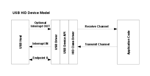
Fig. 5 USB HID Device
This device class uses one or, optionally, two endpoints in addition to endpoint zero. One interrupt IN endpoint carries HID input reports from the device to the host. Output and Feature reports from the host to the device are typically carried via endpoint zero but devices which expect high host-to-device data rates can select to offer an independent interrupt OUT endpoint to carry these. Endpoint zero carries standard USB requests and also HID-specific descriptor requests.
The HID mouse and keyboard device APIs described later in this document are both implemented above the HID Device Class Driver API.
HID Device Class Events
The HID device class driver sends the following events to the application callback functions:
Receive Channel Events
USB_EVENT_CONNECTED
USB_EVENT_DISCONNECTED
USB_EVENT_RX_AVAILABLE
USB_EVENT_ERROR
USB_EVENT_SUSPEND
USB_EVENT_RESUME
USBD_HID_EVENT_IDLE_TIMEOUT
USBD_HID_EVENT_GET_REPORT_BUFFER
USBD_HID_EVENT_GET_REPORT
USBD_HID_EVENT_SET_PROTOCOL
USBD_HID_EVENT_GET_PROTOCOL
USBD_HID_EVENT_SET_REPORT
USBD_HID_EVENT_REPORT_SENT
Note: The USB_EVENT_DISCONNECTED event is not be reported to the application if the MCU’s PB1/USB0VBUS pin is connected to a fixed +5 Volts rather than directly to the VBUS pin on the USB connector or if the USB controller is configured to force device mode.
Transmit Channel Events
USB_EVENT_TX_COMPLETE
Using the HID Device Class Driver
To add a USB HID interface to your application using the HID Device Class Driver, take the following steps.
Add the following header files to the source file(s) which are to support USB:
#include "ti/usblib/msp432e4/usblib.h"
#include "ti/usblib/msp432e4/usbhid.h"
#include "ti/usblib/msp432e4/device/usbdevice.h"
#include "ti/usblib/msp432e4/device/usbdhid.h"
Define the string table which is used to describe various features of your new device to the host system. The following is the string table taken from the
usb_dev_mouseexample application. Edit the actual strings to suit your application and take care to ensure that you also update the length field (the first byte) of each descriptor to correctly reflect the length of the string and descriptor header. The number of strings included varies depending upon the device but must be at least 5. HID report descriptors may refer to string IDs and, if the descriptor for your device includes these, additional strings are required. Also, if multiple languages are reported in string descriptor 0, you must ensure that you have strings available for each language with all language 1 strings occurring in order in a block before all language 2 strings and so on.
//*****************************************************************************
//
// The languages supported by this device.
//
//*****************************************************************************
const uint8_t g_pui8LangDescriptor[] =
{
    4,
    USB_DTYPE_STRING,
    USBShort(USB_LANG_EN_US)
};

//*****************************************************************************
//
// The manufacturer string.
//
//*****************************************************************************
const uint8_t g_pui8ManufacturerString[] =
{
    (17 + 1) * 2,
    USB_DTYPE_STRING,
    'T', 0, 'e', 0, 'x', 0, 'a', 0, 's', 0, ' ', 0, 'I', 0, 'n', 0, 's', 0,
    't', 0, 'r', 0, 'u', 0, 'm', 0, 'e', 0, 'n', 0, 't', 0, 's', 0,
};

//*****************************************************************************
//
// The product string.
//
//*****************************************************************************
const uint8_t g_pui8ProductString[] =
{
    (13 + 1) * 2,
    USB_DTYPE_STRING,
    'M', 0, 'o', 0, 'u', 0, 's', 0, 'e', 0, ' ', 0, 'E', 0, 'x', 0, 'a', 0,
    'm', 0, 'p', 0, 'l', 0, 'e', 0
};

//*****************************************************************************
//
// The serial number string.
//
//*****************************************************************************
const uint8_t g_pui8SerialNumberString[] =
{
    (8 + 1) * 2,
    USB_DTYPE_STRING,
    '1', 0, '2', 0, '3', 0, '4', 0, '5', 0, '6', 0, '7', 0, '8', 0
};

//*****************************************************************************
//
// The interface description string.
//
//*****************************************************************************
const uint8_t g_pui8HIDInterfaceString[] =
{
    (19 + 1) * 2,
    USB_DTYPE_STRING,
    'H', 0, 'I', 0, 'D', 0, ' ', 0, 'M', 0, 'o', 0, 'u', 0, 's', 0,
    'e', 0, ' ', 0, 'I', 0, 'n', 0, 't', 0, 'e', 0, 'r', 0, 'f', 0,
    'a', 0, 'c', 0, 'e', 0
};

//*****************************************************************************
//
// The configuration description string.
//
//*****************************************************************************
const uint8_t g_pui8ConfigString[] =
{
    (23 + 1) * 2,
    USB_DTYPE_STRING,
    'H', 0, 'I', 0, 'D', 0, ' ', 0, 'M', 0, 'o', 0, 'u', 0, 's', 0,
    'e', 0, ' ', 0, 'C', 0, 'o', 0, 'n', 0, 'f', 0, 'i', 0, 'g', 0,
    'u', 0, 'r', 0, 'a', 0, 't', 0, 'i', 0, 'o', 0, 'n', 0
};

//*****************************************************************************
//
// The descriptor string table.
//
//*****************************************************************************
const uint8_t * const g_pStringDescriptors[] =
{
    g_pLangDescriptor,
    g_pManufacturerString,
    g_pProductString,
    g_pSerialNumberString,
    g_pHIDInterfaceString,
    g_pConfigString
};

#define NUM_STRING_DESCRIPTORS (sizeof(g_pStringDescriptors) /                \
                                sizeof(uint8_t *))
Develop the HID report descriptors and, if required, physical descriptors for your device and, from these, the HID descriptor itself. Details of how to do this are beyond the scope of this document other than to say that macros in header file
usbdhid.hare included to help add the various tags required in the descriptor. For information on how these descriptors are constructed, please see the “USB Device Class Definition for Human Interface Devices, version 1.11” which can be downloaded from https://www.usb.org/developers/devclass_docs/HID1_11.pdf. The required structures for a BIOS-compatible HID mouse are:
//*****************************************************************************
//
// The report descriptor for the BIOS mouse class device.
//
//*****************************************************************************
static const uint8_t g_pui8ucMouseReportDescriptor[]=
{
    UsagePage(USB_HID_GENERIC_DESKTOP),
    Usage(USB_HID_MOUSE),
    Collection(USB_HID_APPLICATION),
        Usage(USB_HID_POINTER),
        Collection(USB_HID_PHYSICAL),

            //
            // The buttons.
            //
            UsagePage(USB_HID_BUTTONS),
            UsageMinimum(1),
            UsageMaximum(3),
            LogicalMinimum(0),
            LogicalMaximum(1),

            //
            // 3 - 1 bit values for the buttons.
            //
            ReportSize(1),
            ReportCount(3),
            Input(USB_HID_INPUT_DATA | USB_HID_INPUT_VARIABLE |
                  USB_HID_INPUT_ABS),

            //
            // 1 - 5 bit unused constant value to fill the 8 bits.
            //
            ReportSize(5),
            ReportCount(1),
            Input(USB_HID_INPUT_CONSTANT | USB_HID_INPUT_ARRAY |
                  USB_HID_INPUT_ABS),

            //
            // The X and Y axis.
            //
            UsagePage(USB_HID_GENERIC_DESKTOP),
            Usage(USB_HID_X),
            Usage(USB_HID_Y),
            LogicalMinimum(-127),
            LogicalMaximum(127),

            //
            // 2 - 8 bit Values for x and y.
            //
            ReportSize(8),
            ReportCount(2),
            Input(USB_HID_INPUT_DATA | USB_HID_INPUT_VARIABLE |
                  USB_HID_INPUT_RELATIVE),
        EndCollection,
    EndCollection,
};

//*****************************************************************************
//
// The HID class descriptor table. For the mouse class, we have only a single
// report descriptor.
//
//*****************************************************************************
static const uint8_t * const g_pMouseClassDescriptors[] =
{
    g_pucMouseReportDescriptor
};

//*****************************************************************************
//
// The HID descriptor for the mouse device.
//
//*****************************************************************************
static const tHIDDescriptor g_sMouseHIDDescriptor =
{
     9,                                 // bLength
     USB_HID_DTYPE_HID,                 // bDescriptorType
     0x111,                             // bcdHID (version 1.11 compliant)
     0,                                 // bCountryCode (not localized)
     1,                                 // bNumDescriptors
     USB_HID_DTYPE_REPORT,              // Report descriptor
     sizeof(g_pucMouseReportDescriptor) // Size of report descriptor
};
Define an array of
tHIDReportIdlestructures in RAM with one entry for each input report your device supports. Initialize theucDuration4mSanducReportIDfields in each of the entries to set the default idle report time for each input report. Note thatucDuration4mSdefines the idle time in 4mS increments as used in the USB HID Set_Idle and Get_Idle requests. The times defined in these structures are used to determine how often a given input report is resent to the host in the absence of any device state change. For example, a device supporting two input reports with IDs 1 and 2 may initialize the array as follows:
{
    { 125, 1, 0, 0 }, // Report 1 polled every 500mS (4 * 125).
    {   0, 2, 0, 0}   // Report 2 is not polled (0mS timeout)
};
Define a
tUSBDHIDDevicestructure and initialize all fields as required for your application. The following example shows a structure suitable for a BIOS-compatible mouse device which publishes a single input report.
const tUSBDHIDDevice g_sHIDMouseDevice =
{
    //
    // The Vendor ID you have been assigned by USB-IF.
    //
    USB_VID_YOUR_VENDOR_ID,

    //
    // The product ID you have assigned for this device.
    //
    USB_PID_YOUR_PRODUCT_ID,

    //
    // The power consumption of your device in milliamps.
    //
    POWER_CONSUMPTION_MA,

    //
    // The value to be passed to the host in the USB configuration descriptor's
    // bmAttributes field.
    //
    USB_CONF_ATTR_BUS_PWR,

    //
    // This mouse supports the boot subclass.
    //
    USB_HID_SCLASS_BOOT,

    //
    // This device supports the BIOS mouse report protocol.
    //
    USB_HID_PROTOCOL_MOUSE,

    //
    // The device has a single input report.
    //
    1,

    //
    // A pointer to our array of tHIDReportIdle structures. For this device,
    // the array must have 1 element (matching the value of the previous field).
    //
    g_psMouseReportIdle,

    //
    // A pointer to your receive callback event handler.
    //
    YourUSBReceiveEventCallback,

    //
    // A value that you want passed to the receive callback alongside every
    // event.
    //
    (void *)&g_sYourInstanceData,

    //
    // A pointer to your transmit callback event handler.
    //
    YourUSBTransmitEventCallback,

    //
    // A value that you want passed to the transmit callback alongside every
    // event.
    //
    (void *)&g_sYourInstanceData,

    //
    // This device does not want to use a dedicated interrupt OUT endpoint
    // since there are no output or feature reports required.
    //
    false,

    //
    // A pointer to the HID descriptor for the device.
    //
    &g_sMouseHIDDescriptor,

    //
    // A pointer to the array of HID class descriptor pointers for this device.
    // The number of elements in this array and their order must match the
    // information in the HID descriptor provided above.
    //
    g_pMouseClassDescriptors,

    //
    // A pointer to your string table.
    //
    g_pStringDescriptors,

    //
    // The number of entries in your string table. This must equal
    // (1 + (5 + (num HID strings)) * (num languages)).
    //
    NUM_STRING_DESCRIPTORS
};
Add a receive event handler function, YourUSBReceiveEventCallback in the previous example, to your application taking care to handle all messages which require a particular response. For the HID device class the following receive callback events MUST be handled by the application:
USB_EVENT_RX_AVAILABLE
USBD_HID_EVENT_IDLE_TIMEOUT
USBD_HID_EVENT_GET_REPORT_BUFFER
USBD_HID_EVENT_GET_REPORT
USBD_HID_EVENT_SET_PROTOCOL (for BIOS protocol devices)
USBD_HID_EVENT_GET_PROTOCOL (for BIOS protocol devices)
USBD_HID_EVENT_SET_REPORT Although no other events must be handled, USB_EVENT_CONNECTED and USB_EVENT_DISCONNECTED is typically be required since these indicate when a host connects or disconnects and allow the application to flush any buffers or reset state as required. Attempts to send data when the host is disconnected are ignored and result in an error.
Add a transmit event handler function, YourUSBTransmitEventCallback in the previous example, to your application and use USB_EVENT_TX_COMPLETE to indicate when a new report may be scheduled for transmission. While a report is being transmitted, attempts to send another report via
USBDHIDReportWrite()are ignored and results in an error.From your main initialization function call the HID device class driver initialization function to configure the USB controller and place the device on the bus.
pvDevice = USBDHIDMouseInit(0, &g_sHIDMouseDevice);
Assuming
pvDevicereturned is not NULL, your device is now ready to communicate with a USB host.Once the host connects, your control event handler is sent
USB_EVENT_CONNECTEDand the first input report may be sent to the host usingUSBDHIDReportWrite()with following packets transmitted as soon as USB_EVENT_TX_COMPLETE is received via the transmit event handler.
Using the Composite HID Mouse Device Class
When using the HID mouse device class in a composite device, the configuration of the device is very similar to how it is configured as a non-composite device. Follow all of the configuration steps in the previous section with the exception of calling USBDHIDMouseCompositeInit() instead of USBDHIDMouseInit(). This prepares an instance of the HID mouse device class to be enumerated as part of a composite device. The USBDHIDMouseCompositeInit() function takes the mouse device structure and a pointer to a tCompositeEntry value so that it can properly initialize the mouse device and the composite entry that is later be passed to the USBDCompositeInit() function. The code example below provides an example of how to initialize a mouse device to be a part of a composite device.
//
// These should be initialized with valid values for each class.
//
extern tUSBDHIDMouseDevice g_sHIDMouseDevice;

//
// The array of composited devices.
//
tCompositeEntry psCompEntries[2];

//****************************************************************************
//
// Allocate the Device Data for the top level composite device class.
//
//****************************************************************************
tUSBDCompositeDevice g_sCompDevice =
{
    //
    // TI USBLib VID.
    //
    USB_VID_TI_1CBE,

    //
    // PID for composite HID/DFU device.
    //
    USB_PID_COMP_HID_DFU,

    //
    // This is in milliamps.
    //
    500,

    //
    // Bus powered device.
    //
    USB_CONF_ATTR_BUS_PWR,

    //
    // Device event handler function pointer (receives connect, disconnect
    // and other device-level notifications).
    //
    DeviceHandler,

    //
    // The string table.  This is the string table for the main device (no DFU
    // strings are required).
    //
    g_pStringDescriptors,
    NUM_STRING_DESCRIPTORS,

    //
    // The Composite device array.
    //
    NUM_DEVICES,
    g_psCompDevices
};

//
// The OTHER_SIZES here are the sizes of the descriptor data for other classes
// that are part of the composite device.
//
#define DESCRIPTOR_DATA_SIZE    (COMPOSITE_DHID_SIZE + OTHER_SIZES)
uint8_t g_pui8DescriptorData[DESCRIPTOR_DATA_SIZE];

//
// Initialize the HID mouse and its composite entry.
//
pvMouseDevice = USBDHIDMouseCompositeInit(0, &g_sHIDMouseDevice,
                                          &psCompEntries[0]);

...

USBDCompositeInit(0, &g_sCompDevice, DESCRIPTOR_DATA_SIZE,
                  g_pui8DescriptorData);
All other API calls to the USB HID mose device class should use the value returned by USBDHIDMouseCompositeInit() when the API calls for a pvInstance pointer. Also when using the audio device in a composite device the COMPOSITE_DHID_SIZE value should be added to the size of the g_pui8DescriptorData array as shown in the example above.
Handling HID Reports
Communication between a HID device and host takes place using data structures known as “reports”.
Input reports are sent from the device to the host in response to device state changes, queries from the host or a configurable timeout. In the case of a state change, the device sends a new copy of the relevant input report to the host via the interrupt IN endpoint. This is accomplished by calling USBDHIDReportWrite(). Whereas other USB device class drivers require that the application send no more than 1 packet of data in each call to the driver’s “PacketWrite” function, the HID device class driver allows a complete report to be sent. If the report passed is longer than the maximum packet size for the endpoint, the class driver handles the process of breaking it up into multiple USB packets. Once a full report has been transmitted to the host and acknowledged, the application’s transmit event handler receives USB_EVENT_TX_COMPLETE indicating that the application is free to send another report.
The host may also poll for the latest version of an input report. This procedure involves a request on endpoint zero and results in a sequence of events that the application must respond to. On receipt of the Get_Report request, the HID device class driver sends USBD_HID_EVENT_GET_REPORT to the application receive callback. The application must respond to this by returning a pointer to the latest version of the requested report and the size of the report in bytes. This data is then returned to the host via endpoint zero and successful completion of the transmission is notified to the application using USBD_HID_EVENT_REPORT_SENT passed to the receive callback.
One other condition may cause an input report to be sent. Each input report has a timeout associated with it and, when this time interval expires, the report must be returned to the host regardless of whether or not the device state has changed. The timeout is set using a Set_Idle request from the host and may be completely disabled (as is typically done for mice and keyboards when communicating with a Windows PC, for example) by setting the timeout to 0.
The HID device class driver internally tracks the required timeouts for each input report. When a timer expires, indicating that the report must be resent, USBD_HID_EVENT_IDLE_TIMEOUT is sent to the application receive callback. As in the previous case, the application must respond with a pointer to the appropriate report and its length in bytes. In this case, the returned report is transmitted to the host using the interrupt IN endpoint and the successful completion of the transmission is notified to the application using USB_EVENT_TX_COMPLETE sent to the transmit callback. Note that the application returns information on the location and size of the report and MUST NOT call USBDHIDReportWrite() in response to this event.
Output and Feature reports are sent from the host to the device to instruct it to set various parameters and options. A device can chose whether all host-to-device report communication takes place via endpoint zero or whether a dedicated interrupt OUT endpoint is used. Typically host-to-device traffic is low bandwidth and endpoint zero communication can be used but, if a dedicated endpoint is required, the field bUseOutEndpoint in the tUSBDHIDDevice structure for the device should be set to true.
If using a dedicated endpoint for output and feature reports, the application receive callback is called with USB_EVENT_RX_AVAILABLE whenever a report packet is available. During this callback, the application can call USBDHIDPacketRead() to retrieve the packet. If it is not possible to read the packet immediately, the HID device class driver calls the application back later to give it another opportunity. Until the packet is read, NAK is sent to the host preventing more data from being sent.
In the more typical case where endpoint zero is used to transfer output and feature reports, the application can expect the following sequence of events on the receive callback.
USBD_HID_EVENT_GET_REPORT_BUFFER indicates that a Set_Report request has been received from the host and the device class driver is requesting a buffer into which the received report can be written. The application must return a pointer to a buffer which is at least as large as required to store the report.
USBD_HID_EVENT_SET_REPORT follows next once the report data has been read from endpoint zero into the buffer supplied on the earlier USBD_HID_EVENT_GET_REPORT_BUFFER callback. The device class driver does not access the report buffer after this event is sent and the application may handle the memory as it wishes following this point.
HID Mouse Device Class API
The USB HID device class is extremely versatile but somewhat daunting. For applications which want to offer a mouse-like appearance to a USB host, however, the HID Mouse Device Class API may be used without the need to develop any HID-specific software. This high-level interface completely encapsulates the USB stack and USB HID device class driver and allows an application to simply instantiate a USB mouse device and call a single function to notify the USB host of mouse movement and button presses.
The USB mouse device uses the BIOS mouse subclass and protocol so is recognized by the vast majority of host operating systems and BIOSs without the need for additional host-side software. The mouse provides two axis movement (reported to the host in terms of relative position changes) and up to three buttons which may be either pressed or released.
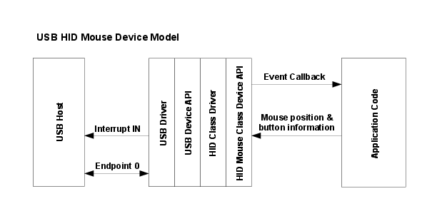
Fig. 6 USB HID Mouse Device
The usb_dev_mouse example application makes use of this device class API.
HID Mouse Device API Events
The HID mouse device API sends the following events to the application callback function:
USB_EVENT_CONNECTED
USB_EVENT_DISCONNECTED
USB_EVENT_TX_COMPLETE
USB_EVENT_ERROR
USB_EVENT_SUSPEND
USB_EVENT_RESUME
Note: The USB_EVENT_DISCONNECTED event is not be reported to the application if the MCU’s USB0VBUS pin is connected to a fixed +5 Volts rather than directly to the VBUS pin on the USB connector or if the USB controller is configured to force device mode.
Using the HID Mouse Device Class API
To add a USB HID mouse interface to your application using the HID Mouse Device Class API, take the following steps.
Add the following header files to the source file(s) which are to support USB:
#include "src/usb.h"
#include "usblib/usblib.h"
#include "usblib/device/usbdhidmouse.h"
Define the string table which is used to describe various features of your new device to the host system. An example of a suitable string table for a mouse device can be found in using_the_hid_device. This table must include a minimum of 6 entries - string descriptor 0 defining the language(s) available and 5 strings for each supported language.
Define a
tUSBDHIDMouseDevicestructure and initialize all fields as required for your application.
const tUSBDHIDMouseDevice g_sMouseDevice =
{
    //
    // The Vendor ID you have been assigned by USB-IF.
    //
    USB_VID_YOUR_VENDOR_ID,

    //
    // The product ID you have assigned for this device.
    //
    USB_PID_YOUR_PRODUCT_ID,

    //
    // The power consumption of your device in milliamps.
    //
    POWER_CONSUMPTION_MA,

    //
    // The value to be passed to the host in the USB configuration descriptor's
    // bmAttributes field.
    //
    USB_CONF_ATTR_SELF_PWR,

    //
    // A pointer to your mouse callback event handler.
    //
    YourMouseHandler,

    //
    // A value that you want passed to the callback alongside every event.
    //
    (void *)&g_sYourInstanceData,

    //
    // A pointer to your string table.
    //
    g_pStringDescriptors,

    //
    // The number of entries in your string table. This must equal
    // (1 + (5 * (num languages))).
    //
    NUM_STRING_DESCRIPTORS
};
Add a mouse event handler function, YourMouseHandler in the previous example, to your application. A minimal implementation can ignore all events though USB_EVENT_TX_COMPLETE can be used to ensure that mouse messages are not sent when a previous report is still in transit to the host. Attempts to send a new mouse report when the previous report has not yet been acknowledged results in return code MOUSE_ERR_TX_ERROR from
USBDHIDMouseStateChange().From your main initialization function call the HID mouse device API initialization function to configure the USB controller and place the device on the bus.
pvDevice = USBDHIDMouseInit(0, &g_sMouseDevice);
Assuming
pvDevicereturned is not NULL, your mouse device is now ready to communicate with a USB host.Once the host connects, your mouse event handler is sent USB_EVENT_CONNECTED after which calls can be made to
USBDHIDMouseStateChange()to inform the host of mouse position and button state changes.
HID Keyboard Device Class API
As with the HID Mouse Device Class API described above, the HID Keyboard Device Class API provides an easy-to-use high-level interface for applications wishing to appear to the USB host as a BIOS-compatible keyboard. The keyboard supports up to 6 simultaneously pressed, non-modifier keys and up to 5 state indication LEDs.
Key press and release notifications along with the state of the modifier keys (Shift, Ctrl, Alt, etc.) are passed to the API in a single API call and a callback informs the application whenever the host requests that the LED states be changed.
Keys are identified to the API by means of USB HID key usage codes. A subset of these are defined in the header file usbhid.h and the full set can be found in the document “Universal Serial Bus (USB) HID Usage Tables” which can be downloaded from https://www.usb.org/developers/devclass_docs/Hut1_12.pdf.
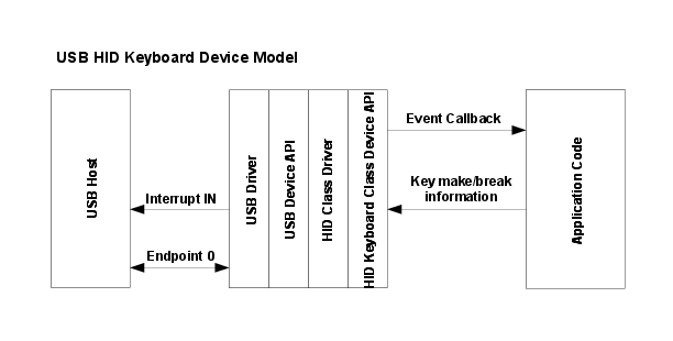
Fig. 7 USB HID Keyboard Device
The usb_dev_keyboard example application makes use of this device class API.
HID Keyboard Device API Events
The HID keyboard device API sends the following events to the application callback function:
USB_EVENT_CONNECTED
USB_EVENT_DISCONNECTED
USB_EVENT_TX_COMPLETE
USB_EVENT_ERROR
USB_EVENT_SUSPEND
USB_EVENT_RESUME
USBD_HID_KEYB_EVENT_SET_LEDS
Note: The USB_EVENT_DISCONNECTED event is not reported to the application if the MCU’s PB1/USB0VBUS pin is connected to a fixed +5 Volts rather than directly to the VBUS pin on the USB connector or if the USB controller is configured to force device mode.
Add the following header files to the source file(s) which are to support USB:
#include "ti/usblib/msp432e4/usblib.h"
#include "ti/usblib/msp432e4/device/usbdhidkeyb.h"
Define the string table which is used to describe various features of your new device to the host system. The string table found in using_the_hid_device illustrates the format required. This table must include a minimum of 6 entries - string descriptor 0 defining the language(s) available and 5 strings for each supported language.
Define a
tUSBDHIDKeyboardDevicestructure and initialize all fields as required for your application.
const tUSBDHIDKeyboardDevice g_sKeyboardDevice =
{
    //
    // The Vendor ID you have been assigned by USB-IF.
    //
    USB_VID_YOUR_VENDOR_ID,

    //
    // The product ID you have assigned for this device.
    //
    USB_PID_YOUR_PRODUCT_ID,

    //
    // The power consumption of your device in milliamps.
    //
    POWER_CONSUMPTION_MA,

    //
    // The value to be passed to the host in the USB configuration descriptor's
    // bmAttributes field.
    //
    USB_CONF_ATTR_SELF_PWR,

    //
    // A pointer to your keyboard callback event handler.
    //
    YourKeyboardHandler,

    //
    // A value that you want passed to the callback alongside every event.
    //
    (void *)&g_sYourInstanceData,

    //
    // A pointer to your string table.
    //
    g_pStringDescriptors,

    //
    // The number of entries in your string table. This must equal
    // (1 + (5 * (num languages))).
    //
    NUM_STRING_DESCRIPTORS
};
Add a keyboard event handler function, YourKeyboardHandler in the previous example, to your application. A minimal implementation can ignore all events since key information is buffered in the API and sent later if
USBDHIDKeyboardKeyStateChange()is called while a previous report transmission remains unacknowledged.From your main initialization function call the HID keyboard device API initialization function to configure the USB controller and place the device on the bus.
pvDevice = USBDHIDKeyboardInit(0, &g_sKeyboardDevice);
Assuming
pvDevicereturned is not NULL, your keyboard device is now ready to communicate with a USB host.Once the host connects, your keyboard event handler is sent USB_EVENT_CONNECTED after which calls can be made to
USBDHIDKeyboardKeyStateChange()to inform the host of key press and release events.
HID Gamepad Device Class API
The HID Gamepad Device Class API provides an interface for applications to provide USB gamepad support to a USB host. The default gamepad supports 3 8-bit signed axis values (X, Y, and Z) and 8 buttons. The USB gamepad is configured to allow the host to poll at 1ms rate for the values. The application calls the USBDHIDGamepadSendReport() function to provide data to the USB library.
Defining a HID Gamepad Device
In order to properly configure an application to function as a HID Gamepad device, there are a few structures that the application must properly declare and pass to the USB library. These include declaring the strings that are passed back to the USB host, the basic configuration of the device and an optional report descriptor to customize the data that is sent back to the USB host.
The following header files are needed to properly define all of the structures needed to implement a USB gamepad device:
#include "ti/usblib/msp432e4/usblib.h"
#include "ti/usblib/msp432e4/usbhid.h"
#include "ti/usblib/msp432e4/device/usbdevice.h"
#include "ti/usblib/msp432e4/device/usbdhid.h"
#include "ti/usblib/msp432e4/device/usbdhidgamepad.h"
The application must first define the string table that is used to describe various features of the device to the host system. A detailed description of how to declare a string table is found in the using_the_hid_device section of this document. This table must include a minimum of 6 entries with the following meanings: languages available, manufacturer name, product description, serial number, HID interface description, and a configuration description.
The application must also provide a gamepad event handler function. This function responds to the USB_EVENTS_ parameter passed to the application when events occur. The HID gamepad device API sends the following events to the application callback function:
USB_EVENT_CONNECTED - USB connection event occurred.
USB_EVENT_DISCONNECTED - USB disconnect event occurred.
USB_EVENT_TX_COMPLETE - A previously scheduled transmit request completed.
USB_EVENT_ERROR - An error prevented the call from completing successfully.
USB_EVENT_SUSPEND - A USB suspend event occurred.
USB_EVENT_RESUME - A USB resume event occurred.
USB_EVENT_LPM_RESUME - A USB LPM resume event occurred.
USB_EVENT_LPM_SLEEP - A USB LPM sleep event occurred.
USB_EVENT_LPM_ERROR - A USB LPM error occurred.
Note: The USB_EVENT_DISCONNECTED event is not reported to the application if the MCU’s USB0VBUS pin is connected to a fixed +5 Volts rather than directly to the VBUS pin on the USB connector or if the USB controller is configured to force device mode using the USBStackModeSet() function.
Note: The __USB_EVENT_LPM_*__ events are not supported on all microcontrollers. Please check the device’s data sheet to see if USB LPM is supported on the device that is in use.
The string table and event handler function are used in the final required structure to complete the definition of the USB game device to the host. The application must define a tUSBDHIDGamepadDevice structure and initialize all fields so that the USB library can enumerate the device to the host.
const tUSBDHIDGamepadDevice g_sGamepadDevice =
{
    //
    // The Vendor ID assigned by USB-IF.
    //
    USB_VID_YOUR_VENDOR_ID,

    //
    // The Product ID assigned to this device.
    //
    USB_PID_YOUR_PRODUCT_ID,

    //
    // The power consumption of the device in milliamps.
    //
    POWER_CONSUMPTION_MA,

    //
    // This value is passed to the host in the USB configuration descriptor's
    // bmAttributes field.
    //
    USB_CONF_ATTR_SELF_PWR,

    //
    // A pointer to the gamepad callback event handler.
    //
    YourGamepadHandler,

    //
    // A value that the application passes to the gamepad callback function.
    //
    (void *)&g_sYourInstanceData,

    //
    // A pointer to the string table for the device.
    //
    g_pStringDescriptors,

    //
    // The number of entries in your string table, which must equal
    // (1 + (5 * (number of languages))).
    //
    NUM_STRING_DESCRIPTORS,

    //
    // An optional override HID descriptor for the gamepad, the value of which
    // can be 0 if the application is using the default gamepad descriptor.
    //
    g_pui8GameReportDescriptor,

    //
    // The size of the optional override HID descriptor for the
    // gamepad, which must be 0 if the application is using the default
    // gamepad descriptor or the size of the custom report descriptor in bytes.
    //
    sizeof(g_pui8GameReportDescriptor)
};
Finally, to initialize a single gamepad device, the application must call the HID gamepad device API initialization function, USBDHIDGamepadInit(), to configure the USB controller and prepare the device to be connected to the host. Assuming the psGamepad returned is not NULL, the gamepad device is now ready to communicate with a USB host.
//
// Initialize a gamepad HID instance.
//
psGamepad = USBDHIDGamepadInit(0, &g_sGamepadDevice);
Once the host connects, your gamepad event handler is sent the USB_EVENT_CONNECTED event after which calls can be made to USBDHIDGamepadSendReport() to provide up to date information from the application to the USB host. After a successful call to USBDHIDGamepadSendReport(), the application must wait for a USB_EVENT_TX_COMPLETE event before sending more data.
tGamepadReport sReport;

...

//
// Send a gamepad HID report.
//
USBDHIDGamepadSendReport(psGamepad, &sReport, sizeof(sReport);
Defining a Custom HID Gamepad Report
This section handles some of the considerations when defining an application-supplied report descriptor. HID report descriptors are infinitely configurable and can be confusing to define properly, so a good understanding of the USB HID specification is required. The USB HID class supported by the USB library is based on the USB HID 1.11 specification available from usb.org, which should be reviewed before attempting to declare a custom report descriptor. The definition of the structure is as similiar as possible to the USB specification to make it as easy as possible to properly define a structure similar to the USB specification.
The example below defines a more complicated 12-bit four-axis controller with 16 buttons. Each of the 4 12-bit values are padded with a single 4-bit constant so that the values are easily accessed by the application. This padding is not required, but does make sending the data much more convenient for the application by allowing a structure like the tCustomReport in the example below. The final value in the report is a single 16-bit value containing the state of all 16 buttons as individual bits.
//*****************************************************************************
//
// The following is the HID report structure definition that is passed back
// to the host.
//
//*****************************************************************************
static const uint8_t g_pui8GameReportDescriptor[] =
{
    UsagePage(USB_HID_GENERIC_DESKTOP),
    Usage(USB_HID_JOYSTICK),
    Collection(USB_HID_APPLICATION),

        //
        // The axis for the controller.
        //
        UsagePage(USB_HID_GENERIC_DESKTOP),
        Usage (USB_HID_POINTER),
        Collection (USB_HID_PHYSICAL),

            //
            // The X, Y, RX, and RY values, which are specified as 8-bit
            // absolute position values.
            //
            Usage (USB_HID_X),

            //
            // 12-bit absolute X value.
            //
            ReportSize(12),
            ReportCount(1),
            Input(USB_HID_INPUT_DATA | USB_HID_INPUT_VARIABLE |
                  USB_HID_INPUT_ABS),

            //
            // 4-bit padding to 16 bits.
            //
            ReportCount(1),
            ReportSize(4),
            Input(USB_HID_INPUT_CONSTANT),

            //
            // 12-bit absolute Y value.
            //
            Usage (USB_HID_Y),
            ReportSize(12),
            ReportCount(1),
            Input(USB_HID_INPUT_DATA | USB_HID_INPUT_VARIABLE |
                  USB_HID_INPUT_ABS),

            //
            // 4-bit padding to 16 bits.
            //
            ReportCount(1),
            ReportSize(4),
            Input(USB_HID_INPUT_CONSTANT),

            //
            // 12-bit absolute RX value.
            //
            Usage (USB_HID_RX),
            ReportSize(12),
            ReportCount(1),
            Input(USB_HID_INPUT_DATA | USB_HID_INPUT_VARIABLE |
                  USB_HID_INPUT_ABS),

            //
            // 4-bit padding to 16 bits.
            //
            ReportCount(1),
            ReportSize(4),
            Input(USB_HID_INPUT_CONSTANT),

            //
            // 12-bit absolute RY value.
            //
            Usage (USB_HID_RY),
            ReportSize(12),
            ReportCount(1),
            Input(USB_HID_INPUT_DATA | USB_HID_INPUT_VARIABLE |
                  USB_HID_INPUT_ABS),

            //
            // 4-bit padding to 16 bits.
            //
            ReportCount(1),
            ReportSize(4),
            Input(USB_HID_INPUT_CONSTANT),

            //
            // The 16 buttons.
            //
            UsagePage(USB_HID_BUTTONS),
            UsageMinimum(1),
            UsageMaximum(16),
            LogicalMinimum(0),
            LogicalMaximum(1),
            PhysicalMinimum(0),
            PhysicalMaximum(1),

            //
            // 16 1-bit values for the buttons.
            //
            ReportSize(1),
            ReportCount(16),
            Input(USB_HID_INPUT_DATA | USB_HID_INPUT_VARIABLE |
                  USB_HID_INPUT_ABS),

        EndCollection,
    EndCollection
};

//*****************************************************************************
//
// The packed custom report structure that is sent to the host to match the
// report descriptor defined above.
//
//*****************************************************************************
typedef struct
{
    uint16_t i16XPos;
    uint16_t i16YPos;
    uint16_t i16RXPos;
    uint16_t i16RYPos;
    uint16_t ui16Buttons;
}
PACKED tCustomReport;
HID Sensor Device Class API
The HID Sensor Device Class API provides an interface for applications to provide USB sensor support to a USB host. Since there are many types of Sensors, the included example represents a Temperature Sensor device. The temperature sensor sends information on its internal temperature, its event and its state. The temperature sensor is configured to allow the host to poll its IN endpoint at 1ms rate for the values. The Sensor device application calls the USDHIDSensorSendReport()function to send the data to its buffer.
Defining a HID Sensor Device
In order to properly configure an application to function as a HID Sensor device, there are a few structures that the application must properly declare and pass to the USB library. These include declaring the strings that are passed back to the USB host, the basic configuration of the device and an optional report descriptor to customize the data that is sent back to the USB host.
The following header files are needed to properly define all of the structures needed to implement a USB sensor device:
#include "ti/usblib/msp432e4/usblib.h"
#include "ti/usblib/msp432e4/usbhid.h"
#include "ti/usblib/msp432e4/device/usbdevice.h"
#include "ti/usblib/msp432e4/device/usbdhid.h"
#include "ti/usblib/msp432e4/device/usbdhidsensor.h"
The application must first define the string table that is used to describe various features of the device to the host system. A detailed description of how to declare a string table is found in the using_the_hid_device section of this document. This table must include a minimum of 6 entries with the following meanings: languages available, manufacturer name, product description, serial number, HID interface description, and a configuration description.
The application must also provide a sensor event handler function. This function responds to the USB_EVENTS_ parameter passed to the application when events occur. The HID sensor device API sends the following events to the application callback function:
USB_EVENT_CONNECTED - USB connection event occurred.
USB_EVENT_DISCONNECTED - USB disconnect event occurred.
USB_EVENT_TX_COMPLETE - A previously scheduled transmit request completed.
USB_EVENT_ERROR - An error prevented the call from completing successfully.
USB_EVENT_SUSPEND - A USB suspend event occurred.
USB_EVENT_RESUME - A USB resume event occurred.
USB_EVENT_LPM_RESUME - A USB LPM resume event occurred.
USB_EVENT_LPM_SLEEP - A USB LPM sleep event occurred.
USB_EVENT_LPM_ERROR - A USB LPM error occurred.
Note: The USB_EVENT_DISCONNECTED event is not reported to the application if the MCU’s USB0VBUS pin is connected to a fixed +5 Volts rather than directly to the VBUS pin on the USB connector or if the USB controller is configured to force device mode using the USBStackModeSet() function.
The string table and event handler function are used in the final required structure to complete the definition of the USB sensor device to the host. The application must define a tUSBDHIDSensorDevice structure and initialize all fields so that the USB library can enumerate the device to the host.
const tUSBDHIDSensorDevice g_sSensorDevice =
{
    //
    // The Vendor ID assigned by USB-IF.
    //
    USB_VID_YOUR_VENDOR_ID,

    //
    // The Product ID assigned to this device.
    //
    USB_PID_YOUR_PRODUCT_ID,

    //
    // The power consumption of the device in milliamps.
    //
    POWER_CONSUMPTION_MA,

    //
    // This value is passed to the host in the USB configuration descriptor's
    // bmAttributes field.
    //
    USB_CONF_ATTR_SELF_PWR,

    //
    // A pointer to the sensor callback event handler.
    //
    YourSensorHandler,

    //
    // A value that the application passes to the sensor callback function.
    //
    (void *)&g_sYourInstanceData,

    //
    // A pointer to the string table for the device.
    //
    g_pStringDescriptors,

    //
    // The number of entries in your string table, which must equal
    // (1 + (5 * (number of languages))).
    //
    NUM_STRING_DESCRIPTORS,


};
Finally, to initialize a single sensor device, the application must call the HID sensor device API initialization function, USBDHIDSensorInit(), to configure the USB controller and prepare the device to be connected to the host. Assuming the psSensor returned is not NULL, the sensor device is now ready to communicate with a USB host.
//
// Initialize a sensor HID instance.
//
psSensor = USBDHIDSensorInit(0, &g_sSensorDevice);
Once the host connects, your sensor event handler is sent the USB_EVENT_CONNECTED event after which calls can be made to USBDHIDSensorSendReport() to provide up-to-date information from the application to the USB host. After a successful call to USBDHIDSensorSendReport(), the application must wait for a USB_EVENT_TX_COMPLETE event before sending more data.
tGamepadReport sReport;

...

//
// Send a sensor HID report.
//
USBDHIDSensorSendReport(psSensor, &sReport, sizeof(sReport);
Defining a Sensor HID Report
This section handles some of the considerations when defining an application-supplied report descriptor. HID report descriptors are infinitely configurable and can be confusing to define properly, so a good understanding of the USB HID specification is required. The USB HID class supported by the USB library is based on the USB HID 1.11 specification available from usb.org, which should be reviewed before attempting to declare a report descriptor. The definition of the structure is as similiar as possible to the USB specification to make it as easy as possible to properly define a structure similar to the USB specification.
The example below defines a Temperature sensor device which sends to the host sensor temperature, sensor state and sensor event as part of an Input report. Sensor temperature is defined as a 16-bit value while both sensor state and event are defined as two 8 bit values. These values are defined in the structure tSensorTemperatureReport())
//*****************************************************************************
//
// The following is the HID report structure definition that is passed back
// to the host.
//
//*****************************************************************************
static const uint8_t g_pui8SensorReportDescriptor[] =
{
     //UsagePage(USB_HID_SENSOR),               // uncomment this line and comment
                                                // the vendor defined usage page to
                                                // identify the device as a sensor
                                                // in Windows 10.

     0x06, 0x00, 0xff,                          //UsagePage(Vendor Defined)
     Usage(USB_HID_ENVIRONMENTAL_TEMPERATURE),
     Collection(USB_HID_PHYSICAL),
//     0x85, 0x01,    // Report ID (Vendor Defined)

     UsagePage(USB_HID_SENSOR),
     HidUsageSensorPropertyReportingState,           //HID_USAGE_SENSOR_PROPERTY_REPORTING_STATE,
     LogicalMinimum(0),
     LogicalMaximum(5),
     ReportSize(8),
     ReportCount(1),
     Feature(USB_HID_INPUT_DATA | USB_HID_INPUT_ARRAY |USB_HID_INPUT_ABS ),   //Data_Arr_Abs

     HidUsageSensorPropertySensorStatus,                            //HID_USAGE_SENSOR_PROPERTY_SENSOR_STATUS,
     LogicalMinimum(0),
     LogicalMaximum32(0xFF,0xFF,0xFF,0xFF),
     ReportSize(32),
     ReportCount(1),
     Feature(USB_HID_INPUT_DATA | USB_HID_INPUT_VARIABLE | USB_HID_INPUT_ABS),   // Data_Var_Abs up to VT_UI4 worth of status info

     HidUsageSensorPropertyReportInterval,
     LogicalMinimum(0),
     LogicalMaximum32(0xFF,0xFF,0xFF,0xFF),
     ReportSize(32),
     ReportCount(1),
     UnitExponent(0),
     Feature(USB_HID_INPUT_DATA | USB_HID_INPUT_VARIABLE | USB_HID_INPUT_ABS),

     0x0A,0x0F,0x03,                            //HID_USAGE_SENSOR_PROPERTY_CHANGE_SENSITIVITY_ABS,
     LogicalMinimum(0),
     LogicalMinimum16(0xFF,0xFF),
     ReportSize(16),
     ReportCount(1),
     UnitExponent(0x0E), // scale default unit “Celsius” to provide 2 digits past the decimal point
     Feature(USB_HID_INPUT_DATA | USB_HID_INPUT_VARIABLE | USB_HID_INPUT_ABS),    //Data_Var_Abs

     //UsagePage(USB_HID_SENSOR),                //uncomment this line and comment
                                                 // the vendor defined usage page to
                                                 // identify the device as a sensor
                                                 // in Windows 10.
     0x06, 0x00, 0xff,                           //UsagePage(Vendor Defined)
     HidUsageSensorState,
     LogicalMinimum(0),
     LogicalMaximum(6),
     ReportSize(8),
     ReportCount(1),
     Input(USB_HID_INPUT_CONSTANT | USB_HID_INPUT_ARRAY | USB_HID_INPUT_ABS),

     HidUsageSensorEvent,
     LogicalMinimum(0),
     LogicalMaximum(16),
     ReportSize(8),
     ReportCount(1),
     Input(USB_HID_INPUT_CONSTANT | USB_HID_INPUT_ARRAY | USB_HID_INPUT_ABS),

     HidUsageSensorDataEnvironmentalTemperature,
     LogicalMinimum16(01, 0x80),  // LOGICAL_MINIMUM (-32767)
     LogicalMaximum16(0xFF,0x7F),   // LOGICAL_MAXIMUM (32767)
     ReportSize(16),
     ReportCount(1),
     UnitExponent(0x0E),  // scale default unit “Celsius” to provide 2 digits past the decimal point
     Input(USB_HID_INPUT_CONSTANT | USB_HID_INPUT_VARIABLE | USB_HID_INPUT_ABS),
     EndCollection


};


//*****************************************************************************
//
// The packed custom report structure that is sent to the host to match the
// report descriptor defined above.
//
//*****************************************************************************
typedef struct
{
    uint16_t i16XPos;
    uint16_t i16YPos;
    uint16_t i16RXPos;
    uint16_t i16RYPos;
    uint16_t ui16Buttons;
}
PACKED tCustomReport;
Mass Storage Device Class API
The USB mass storage device class allows an application to act as a physical storage device for use by another USB application or for a host operating system. Because the type of storage can vary per application, the mass storage class abstracts the storage with a set of block based APIs that are provided by the application to the USB library. These APIs allow the USB mass storage class to call an external set of functions that actually perform the operations on the physical storage media. The storage APIs are given to the USB library’s mass storage device class initialization function and are called by the USB library whenever it needs to access the physical media. The mass storage class implementation does not require any run time calls once it is initialized. This is because all interaction with the mass storage class occur through the callback function that is provided to the USB library’s mass storage class interface. The callback function is used to notify the application when the device is being read, written or has gone idle. Depending on the operating system and how it accesses the mass storage device, these callbacks may occur at a very rapid rate (once per block) or slower (once per file). The USB library’s mass storage class also provides an interface to inform the USB library when the media status has changed in case the physical media can be ejected. This is important for devices like SD cards that can be removed before the device is connected or even while the device is running.
Some care must be taken by the application if it wishes to share the media with the mass storage class. Proper access protection must be in place as the mass storage class may be using the media access functions during the USB interrupt.
Initialization
The USB library’s mass storage class provides a simple interface to initialize the mass storage class and pass it the needed functions to access a device without having any knowledge of the physical media. The USBDMSCInit() function is the only initialization required by the mass storage class and it uses the structure tUSBDMSCDevice to hold all customizable values for the mass storage class.
Customization
The USB library’s mass storage class provides the ability to customize how the device is reported to the USB host controller in the tUSBDMSCDevice structure. The members of this structure contain all of the customizable parameters.
VID and PID
The VID and PID values reported to the host controller are provided in the usVID and usPID members of the tUSBDMSCDevice structure and should be valid for the application and unique for all vendors and devices. The mass storage device class also reports some class specific strings to the operating system which can be customized in the pucVendor, pucProduct, and pucVersion structure members. These strings may or may not be requested by the USB host controller, however they are required. The pucVendor member is an 8 byte character string for the Vendor, and should be exactly 8 bytes padded with spaces(for example: “TI “). The pucProduct member is a 16 character string that indicates the product type and it too should be padded out with spaces to 16 bytes(for example: “Mass Storage “). The last customizable mass storage string is contained in pucVersion member and is a character based version which should be a 4 bytes padded with spaces (for example: “1.00”).
Power Configuration
The power configuration for the mass storage class device is held in two of the tUSBDMSCDevice members variables, usMaxPowermA and ucPwrAttributes. The usMaxPowermA variable holds the maximum power consumption for the device and is expressed in milliamps. The power configuration is held in the ucPwrAttributes member variable and indicates whether the device is self or bus powered. Valid values are USB_CONF_ATTR_SELF_PWR or USB_CONF_ATTR_BUS_PWR.
Device Strings
The remaining USB strings are contained in the ppui8StringDescriptors and are just like the strings that are used in every other device class in the USB library. The ppui8StringDescriptors is a pointer to the string descriptor array for this device. This array must contain the following string descriptor pointers in this order. Language descriptor, Manufacturer name string (language 1), Product name string (language 1), Serial number string (language 1), MSC Interface description string (language 1), Configuration description string (language 1). If the device is supporting more than 1 language, the descriptor block (except for string descriptor 0) must be repeated for each language defined in the language descriptor. The number of descriptors provided in the ppui8StringDescriptors array must be ((5 + (num MSC strings)) * (num languages)) + 1.
Media Access Functions
The media access functions are passed in to the USB mass storage device class in the sMediaFunctions member variable. This structure holds the access functions for the media used by this instance of the mass storage class device. All of the functions in this structure are required to be filled out with valid functions. These function is called by the USB mass storage device class whenever it needs to read or write the physical media an
Event Callbacks
In some cases the application may need to be informed when the state of the mass storage device has changed. The pfnEventCallback member of the tUSBDMSCDevice structure provides event notification to applications for the following events: USBD_MSC_EVENT_IDLE, USBD_MSC_EVENT_READING, and USBD_MSC_WRITING. When the function of type tUSBCallback is called, only the first two parameters pvCBData and ui32Event parameters are valid. The pvCBData is the value that was returned when the application called USBDMSCInit() and can be used with other APIs. The ui32Event parameter is one of the __USBD_MSC_EVENT_*__ values.
Using the Mass Storage Device Class
The following sections has some coding examples for the initialization of the mass storage class structures as well as how to call the initialization function itself.
const tUSBDMSCDevice g_sMSCDevice =
{
    //
    // Vendor ID.
    //
    USB_VID_TI_1CBE,

    //
    // Product ID.
    //
    USB_PID_MSC,

    //
    // Vendor Information.
    //
    "TI      ",

    //
    // Product Identification.
    //
    "Mass Storage    ",

    //
    // Revision.
    //
    "1.00",

    //
    // 500mA.
    500,

    //
    // Bus Powered.
    //
    USB_CONF_ATTR_BUS_PWR,

    //
    // A list of string descriptors and the number of descriptors.
    //
    g_pStringDescriptors,
    NUM_STRING_DESCRIPTORS,

    //
    // The media access functions.
    //
    {
        USBDMSCStorageOpen,
        USBDMSCStorageClose,
        USBDMSCStorageRead,
        USBDMSCStorageWrite,
        USBDMSCStorageNumBlocks
    },

    //
    // The event notification call back function.
    //
    USBMSCDEventCallback,
};
The initialization and configuration calls for the USB library’s mass storage device class are handled by a single call that passes in the tUSBDMSCDevice structure.
//
// Pass our device information to the USB library and place the device
// on the bus.
//
USBDMSCInit(0, (tUSBDMSCDevice *)&g_sMSCDevice);

//
// Drop into the main loop.
//
while(1)
{
}
The application’s event call back function provides the application with notifications of changes in the USB mass storage class. The application can use this information to update it’s own state. The events may occur in rapid succession and the application must be careful not to spend much time in this function as it is called from a interrupt handler. The application should expect many calls to this function during USB transfers.
uint32_t
USBDMSCEventCallback(void *pvCBData, uint32_t ui32Event,
                     uint32_t ui32MsgParam, void *pvMsgData)
{
    switch(ui32Event)
    {
        //
        // Writing to the device.
        //
        case USBD_MSC_EVENT_WRITING:
        {
            //
            //  Handle write case.
            //

            ...

            break;
        }

        //
        // Reading from the device.
        //
        case USBD_MSC_EVENT_READING:
        {
            //
            //  Handle read case.
            //

            ...

            break;
        }
        case USBD_MSC_EVENT_IDLE:
        {
            //
            //  Handle idle case.
            //

            ...

        }
        default:
        {
            break;
        }
    }
    return(0);
}
Using the Composite Mass Storage Device Class
When using the mass storage device class in a composite device, the configuration of the device is very similar to how it is configured as a non-composite device. Follow all of the configuration steps in the previous section with the exception of calling USBDMSCCompositeInit() instead of USBDMSCInit(). This prepares an instance of the mass storage device class to be enumerated as part of a composite device. The return value from the USBDMSCCompositeInit() function should be placed in the pvInstance member of the tCompositeEntry structure for the mass storage device. The code example below provides an example of how to initialize some of the structures necessary to use the USB mass storage device class in a composite device.
//
// These should be initialized with valid values for each class.
//
extern tUSBDMSCDevice g_sMSCDevice;

//
// The array of composite device entries.
//
tCompositeEntry psCompEntries[2];

//
// Allocate the device data for the top level composite device class.
//
tUSBDCompositeDevice g_sCompDevice =
{
    //
    // Texas Intruments C-Series VID.
    //
    USB_VID_TI_1CBE,

    //
    // Texas Intruments C-Series PID for composite serial device.
    //
    USB_PID_YOUR_COMPOSITE_PID,

    //
    // This is in 2mA increments so 500mA.
    //
    250,

    //
    // Bus powered device.
    //
    USB_CONF_ATTR_BUS_PWR,

    //
    // Composite event handler.
    //
    EventHandler,

    //
    // The string table.
    //
    g_pui8StringDescriptors,
    NUM_STRING_DESCRIPTORS,

    //
    // The Composite device array.
    //
    2,
    g_psCompEntries
};

//
// The OTHER_SIZES here are the sizes of the descriptor data for other classes
// that are part of the composite device.
//
#define DESCRIPTOR_DATA_SIZE    (COMPOSITE_DMSC_SIZE + OTHER_SIZES)
uint8_t g_pui8DescriptorData[DESCRIPTOR_DATA_SIZE];

//
// Save the instance data for this mass storage device.
//
pvAudioDevice = USBDMSCCompositeInit(0, &g_sMSCDevice, &psCompEntries[0]);

...

//
// Initialize the USB controller as a composite device.
//
USBDCompositeInit(0, &g_sCompDevice, DESCRIPTOR_DATA_SIZE,
                  g_pui8DescriptorData);
All other API calls to the USB mass storage device class should use the value returned by USBDAudioCompositeInit() when the API calls for a pvInstance pointer. Also when using the audio device in a composite device the COMPOSITE_DMSC_SIZE value should be added to the size of the g_pui8DescriptorData array as shown in the example above.
Using the USB Device API
If an existing USB Device Class Driver is not suitable for your application, you may choose to develop your device using the lower-level USB Device API instead. This offers greater flexibility but involves somewhat more work. Creating a device application using the USB Device API involves several steps:
Build device, configuration, interface and endpoint descriptor structures to describe your device.
Write handlers for each of the USB events your device is interested in receiving from the USB library.
Call the USB Device API to connect the device to the bus and manage standard host interaction on your behalf.
The following sections walk through each of these steps offering code examples to illustrate the process. Working examples illustrating use of the library can also be found in the DriverLib release for your USB-capable evaluation kit.
The term “device code” used in the following sections describes all class specific code written above the USB Device API to implement a particular USB device application. This may be either application code or a USB device class driver.
Building Descriptors
The USB Device API manages all standard USB descriptors on behalf of the device. These descriptors are provided to the library via four fields in the tDeviceInfo structure which is passed on a call to USBDCDInit(). The relevant fields are:
psDeviceDescriptor
ppui8ConfigDescriptors
ppui8StringDescriptors
ui32NumStringDescriptors
All descriptors are provided as pointers to arrays of uint8_tacters where the contents of the individual descriptor arrays are USB 2.0-compliant descriptors of the appropriate type. For examples of particular descriptors, see the main source files for each of the USB device class drivers (for example device/usbdbulk.c for the generic bulk device class driver) or the file usbdescriptors.c in the qs-scope example application.
tDeviceInfo.pDeviceDescriptor
This array must hold the device descriptor that the USB Device API returns to the host in response to a GET_DESCRIPTOR(DEVICE) request. The following example contains the device descriptor provided by a USB HID keyboard device.
const uint8_t g_pui8DeviceDescriptor[] =
{
    18,                         // Size of this structure.
    USB_DTYPE_DEVICE,           // Type of this structure.
    USBShort(0x200),            // USB version 2.0.
    USB_CLASS_DEVICE,           // USB Device Class.
    0,                          // USB Device Sub-class.
    USB_HID_PROTOCOL_NONE,      // USB Device protocol.
    64,                         // Maximum packet size for default pipe.
    USBShort(USB_VID_TI_1CBE), // Vendor ID (VID).
    USBShort(USB_PID_KEYBOARD), // Product ID (PID).
    USBShort(0x100),            // Device Version BCD.
    1,                          // Manufacturer string identifier.
    2,                          // Product string identifier.
    3,                          // Product serial number.
    1                           // Number of configurations.
};
Header file usblib.h contains macros and labels to help in the construction of descriptors and individual device class header files, such as usbhid.h and device/usbdhid.h for the Human Interface Device class, provide class specific values and labels.
tDeviceInfo.ppui8ConfigDescriptors
While only a single device descriptor is required, multiple configuration descriptors may be offered so the ppui8ConfigDescriptors field is an array of pointers to tConfigHeader structures, each defining the descriptor for a single configuration. The number of entries in this array must agree with the number of configurations specified in the final byte of the device descriptor provided in the psDeviceDescriptor field.
To allow flexibility when defining composite devices, individual configuration descriptors are also defined in terms of an array of structures. In this case, the tConfigHeader structure contains a count and a pointer to an array of tConfigSection structures each of which contains a pointer to a block of bytes and a size indicating the number of bytes in the section. The sections described in this array are concatenated to generate the full config descriptor published to the host.
Config descriptors are somewhat more complex than device descriptors due to the amount of additional information passed alongside the basic configuration descriptor. In addition to USB 2.0 standard descriptors for the configuration, interfaces and endpoints in use, additional, class specific, descriptors may also be included.
The USB Device API imposes one restriction on configuration descriptors that devices must be aware of. While the USB 2.0 specification does not restrict the values that can be specified in the bConfigurationValue field (byte 6) of the configuration descriptor, the USB Device API requires that individual configurations are numbered consecutively starting at 1 for the first configuration.
The following example contains the configuration descriptor structures provided for a USB HID keyboard. This example offers a single configuration containing one interface and using a single interrupt endpoint. In this case, in addition to the standard portions of the descriptor, a Human Interface Device (HID) class descriptor is also included. Due to the use of a standard format for descriptor headers, the USB Device API is capable of safely skipping device specific descriptors when parsing these structures.
In this example, we illustrate the use of multiple sections to build the configuration descriptor. The content of the config descriptor given here is, however, static so it could easily have been defined in terms of a single tConfigSection entry instead. The label g_pucReportDescriptor is assumed to be a pointer to a HID-specific report descriptor for the keyboard.
Note that the value used to initialize the wTotalLength field of the configuration descriptor is irrelevant since the USB library calculates this based on the content of the sections that are concatenated to build the final descriptor.
//*****************************************************************************
//
// HID keyboard device configuration descriptor.
//
// It is vital that the configuration descriptor bConfigurationValue field
// (byte 6) is 1 for the first configuration and increments by 1 for each
// additional configuration defined here.  This relationship is assumed in the
// device stack for simplicity even though the USB 2.0 specification imposes
// no such restriction on the bConfigurationValue values.
//
//*****************************************************************************
const uint8_t g_pui8KeyboardDescriptor[] =
{
    //
    // Configuration descriptor header.
    //
    9,                          // Size of the configuration descriptor.
    USB_DTYPE_CONFIGURATION,    // Type of this descriptor.
    USBShort(34),               // The total size of this full structure
                                // (Value is patched by the USB library so is
                                // not important here)
    1,                          // The number of interfaces in this
                                // configuration.
    1,                          // The unique value for this configuration.
    5,                          // The string identifier that describes this
                                // configuration.
    USB_CONF_ATTR_SELF_PWR,     // Bus Powered, Self Powered, remote wakeup.
    125,                        // The maximum power in 2mA increments.
};

//*****************************************************************************
//
// The interface and HID descriptors for the keyboard device.
//
//*****************************************************************************
uint8_t g_pui8HIDInterface[] =
{
    //
    // HID Device Class Interface Descriptor.
    //
    9,                          // Size of the interface descriptor.
    USB_DTYPE_INTERFACE,        // Type of this descriptor.
    0,                          // The index for this interface.
    0,                          // The alternate setting for this interface.
    1,                          // The number of endpoints used by this
                                // interface.
    USB_CLASS_HID,              // The interface class
    USB_HID_SCLASS_BOOT,        // The interface sub-class.
    USB_HID_PROTOCOL_KEYB,      // The interface protocol for the sub-class
                                // specified above.
    4,                          // The string index for this interface.

    //
    // HID Descriptor.
    //
    9,                          // Size of this HID descriptor.
    USB_HID_DTYPE_HID,          // HID descriptor type.
    USBShort(0x101),            // Version is 1.1.
    0,                          // Country code is not specified.
    1,                          // Number of descriptors.
    USB_HID_DTYPE_REPORT,       // Type of this descriptor.
    USBShort(sizeof(g_pucReportDescriptor)),
                                // Length of the Descriptor.
};

//*****************************************************************************
//
// The interrupt IN endpoint descriptor for the HID keyboard.
//
//*****************************************************************************
const uint8_t g_pui8HIDInEndpoint[] =
{
    //
    // Interrupt IN endpoint descriptor
    //
    7,                               // The size of the endpoint descriptor.
    USB_DTYPE_ENDPOINT,              // Descriptor type is an endpoint.
    USB_EP_DESC_IN | USB_EP_TO_INDEX(INT_IN_ENDPOINT),
    USB_EP_ATTR_INT,                 // Endpoint is an interrupt endpoint.
    USBShort(INT_IN_EP_MAX_SIZE),    // The maximum packet size.
    16,                              // The polling interval for this endpoint.
};

//*****************************************************************************
//
// The HID keyboard config descriptor is defined using three sections:
//
// 1. The 9 byte configuration descriptor.
// 2. The interface and HID report descriptors.
// 4. The mandatory interrupt IN endpoint descriptor (FLASH).
//
//*****************************************************************************
const tConfigSection g_sKeyboardConfigSection =
{
    sizeof(g_pKeyboardDescriptor),
    g_pKeyboardDescriptor
};

const tConfigSection g_sHIDInterfaceSection =
{
    sizeof(g_pHIDInterface),
    g_pHIDInterface
};

const tConfigSection g_sHIDInEndpointSection =
{
    sizeof(g_pHIDInEndpoint),
    g_pHIDInEndpoint
};

//*****************************************************************************
//
// This array lists all the sections that must be concatenated to make a
// single, complete HID keyboard configuration descriptor.
//
//*****************************************************************************
const tConfigSection *g_psKeyboardSections[] =
{
    &g_sKeyboardConfigSection,
    &g_sHIDInterfaceSection,
    &g_sHIDInEndpointSection
};

#define NUM_KEYBOARD_SECTIONS (sizeof(g_psKeyboardSections) /                 \
                               sizeof(tConfigSection *))

//*****************************************************************************
//
// The header for the single configuration we support. This is the root of
// the data structure that defines all the bits and pieces that are pulled
// together to generate the HID keyboard's config descriptor.  A pointer to
// this structure is used to initialize the ppui8ConfigDescriptors field of
// the tDeviceInfo structure passed to USBDCDInit().
//
//*****************************************************************************
const tConfigHeader g_sKeyboardConfigHeader =
{
    NUM_KEYBOARD_SECTIONS,
    g_psKeyboardSections
};
tDeviceInfo.ppui8StringDescriptors and tDeviceInfo.ui32NumStringDescriptors
Descriptive strings referenced by device and configuration descriptors are provided to the USB Device API as an array of string descriptors containing the basic descriptor length and type header followed by a Unicode string. The various string identifiers passed in other descriptors are indexes into the pStringDescriptor array. The first entry of the string descriptor array has a special format and indicates the languages supported by the device.
The field ui32NumStringDescriptors indicates the number of individual string descriptors in the ppui8StringDescriptors array.
The string descriptor array provided to the USB Device API for a USB HID keyboard follows.
//****************************************************************************
//
// The languages supported by this device.
//
//****************************************************************************
const uint8_t g_pui8LangDescriptor[] =
{
    4,
    USB_DTYPE_STRING,
    USBShort(USB_LANG_EN_US)
};

//****************************************************************************
//
// The manufacturer string.
//
//****************************************************************************
const uint8_t g_pui8ManufacturerString[] =
{
    (17 + 1) * 2,
    USB_DTYPE_STRING,
    'T', 0, 'e', 0, 'x', 0, 'a', 0, 's', 0, ' ', 0, 'I', 0, 'n', 0, 's', 0,
    't', 0, 'r', 0, 'u', 0, 'm', 0, 'e', 0, 'n', 0, 't', 0, 's', 0,
};

//****************************************************************************
//
// The product string.
//
//****************************************************************************
const uint8_t g_pui8ProductString[] =
{
    (16 + 1) * 2,
    USB_DTYPE_STRING,
    'K', 0, 'e', 0, 'y', 0, 'b', 0, 'o', 0, 'a', 0, 'r', 0, 'd', 0, ' ', 0,
    'E', 0, 'x', 0, 'a', 0, 'm', 0, 'p', 0, 'l', 0, 'e', 0
};

//****************************************************************************
//
// The serial number string.
//
//****************************************************************************
const uint8_t g_pui8SerialNumberString[] =
{
    (8 + 1) * 2,
    USB_DTYPE_STRING,
    '1', 0, '2', 0, '3', 0, '4', 0, '5', 0, '6', 0, '7', 0, '8', 0
};

//****************************************************************************
//
// The array of string descriptors needed by the enumeration code.
//
//****************************************************************************
const uint8_t * const g_ppui8StringDescriptors[] =
{
    g_pui8LangDescriptor,
    g_pui8ManufacturerString,
    g_pui8ProductString,
    g_pui8SerialNumberString
};
In this example, the ppui8StringDescriptors member of the tDeviceInfo structure would be initialized with the value g_ppui8StringDescriptors and the ui32NumStringDescriptors member would be set to the number of elements in the g_ppui8StringDescriptors array.
USB Event Handlers
The majority of the work in a USB device application is carried out either in the context of, or in response to callbacks from the USB Device API. These callback functions are made available to the USB Device API in the sCallbacks field of the tDeviceInfo structure passed in a call to USBDCDInit().
Field sCallbacks is a structure of type tCustomHandlers which contains a function pointer for each USB event. The application must populate the table with valid function pointers for each event that it wishes to be informed of. Setting any function pointer to NULL disables notification for that event.
The tCustomHandlers structure contains the following fields: * pfnGetDescriptor * pfnRequestHandler * pfnInterfaceChange * pfnConfigChange * pfnDataReceived * pfnDataSent * pfnResetHandler * pfnSuspendHandler * pfnResumeHandler * pfnDisconnectHandler * pfnEndpointHandler * pfnDeviceHandler
Note that all callbacks except the pfnDeviceHandler entry are made in interrupt context. It is, therefore, vital that handlers do not block or make calls to functions which cannot safely be made in an interrupt handler.
pfnGetDescriptor
Standard USB device, configuration and string descriptors are handled by the USB Device API internally but some device classes also define additional, class specific descriptors. In cases where the host requests one of these non-standard descriptors, this callback is made to give the device code an opportunity to provide its own descriptor to satisfy the request.
If the device can satisfy the request, it must call USBDCDSendDataEP0() to provide the requested descriptor data to the host. If the request cannot be satisfied, the device should call USBDCDStallEP0() to indicate that the descriptor request is not supported.
If this member of sCallbacks is set to NULL, the USB Device API stalls endpoint zero whenever it receives a request for a non-standard descriptor.
pfnRequestHandler
The USB Device API contains handlers for all standard USB requests (as defined in Table 9-3 of the USB 2.0 specification) where a standard request is indicated by bits 5 and 6 of the request structure bmRequestType field being clear. If a request is received with a non-standard request type, this callback is made to give the device code an opportunity to satisfy the request.
The callback function receives a pointer to a standard, 8 byte request structure of type tUSBRequest containing information on the request type, the request identifier and various request-specific parameters. The structure also contains a length field, wLength, which indicates how much (if any) data follows in the data stage of the USB transaction. Note that this data is not available at the time the callback is made and the device code is responsible for requesting it using a call to USBDCDRequestDataEP0() if required.
The sequence required when additional data is attached to the request is as follows:
Parse the request to determine the request type and verify that it is handled by the device. If not, call
USBDCDStallEP0()to indicate the problem.If the request is to be handled and
wLengthis non-zero, indicating that additional data is required, callUSBDCDRequestDataEP0()passing a pointer to the buffer into which the data is to be written and the number of bytes of data to receive.Call
USBDevEndpointDataAck()to acknowledge reception of the initial request transmission. This function is found in the Driver Library USB driver API.
Note that it is important to call USBDCDRequestDataEP0() prior to acknowledging the initial request since the acknowledgment frees the host to send the additional data. By making the calls in this order, the USB Device API is guaranteed to be in the correct state to receive the data when it arrives. Making the calls in the opposite order, creates a race condition which could result in loss of data.
Data received as a result of a call to USBDCDRequestDataEP0() is delivered asynchronously via the pfnDataReceived callback described below.
If this member of sCallbacks is set to NULL, the USB Device API stalls endpoint zero whenever it receives a non-standard request.
pfnInterfaceChange
Based on the configuration descriptor published by the device code, several different alternate interface settings may be supported. In cases where the host wishes to change from the default interface configuration and the USB library determines that the requested alternate setting is supported, this callback is made to inform the device code of the change. The parameters passed provide the new alternate interface (ucAlternateSetting and the interface number (ucInterfaceNum).
This callback is only made once the USB Device API has validated the requested alternate setting. If the requested setting is not available in the published configuration descriptor, the USB Device API stalls endpoint zero to indicate the error to the host and make no callback to the device code.
If this member of sCallbacks is set to NULL, the USB Device API notes the interface change internally but not report it to the device code.
pfnConfigChange
When the host enumerates a device, it ultimately selects the configuration that is to be used and send a SET_CONFIGURATION request to the device. When this occurs, the USB Device API validates the configuration number passed against the device code’s published configuration descriptors then calls the pfnConfigChange callback to inform the device code of the configuration that is to be used.
If this member of sCallbacks is set to NULL, the USB Device API notes the configuration change internally but not report it to the device code.
pfnDataReceived
This callback informs the device code of the arrival of data following an earlier call to USBDCDRequestDataEP0(). On this callback, the received data has been written into the buffer provided to the USB Device API in the pucData parameter to USBDCDRequestDataEP0().
The callback handler does not need to acknowledge the data using a call to USBDevEndpointDataAck() in this case since this acknowledgment is performed within the USB Device API itself.
If this member of sCallbacks is set to NULL, the USB Device API reads endpoint zero data requested via USBDCDRequestDataEP0() but not report its availability to the device code. Devices making use of the USBDCDRequestDataEP0() call must, therefore, ensure that they supply a pfnDataReceived handler.
pfnDataSent
The USBDCDSendDataEP0() function allows device code to send an arbitrarily-sized block of data to the host via endpoint zero. The maximum packet size that can be sent via endpoint zero is, however, 64 bytes so larger blocks of data are sent in multiple packets. This callback function is used by the USB Device API to inform the device code when all data provided in the buffer passed to USBDCDSendDataEP0() has been consumed and scheduled for transmission to the host. On reception of this callback, the device code is free to reuse the outgoing data buffer if required.
If this member of sCallbacks is set to NULL, the USB Device API does not inform the device code when a block of EP0 data is sent.
pfnResetHandler
The pfnResetHandler callback is made by the USB Device API whenever a bus reset is detected. This typically occurs during enumeration. The device code may use this notification to perform any housekeeping required in preparation for a new configuration being set.
If this member of sCallbacks is set to NULL, the USB Device API does not inform the device code when a bus reset occurs.
pfnSuspendHandler
The pfnSuspendHandler callback is made whenever the USB Device API detects that suspend has been signaled on the bus. Device code may make use of this notification to, for example, set appropriate power saving modes.
If this member of sCallbacks is set to NULL, the USB Device API does not inform the device code when a bus suspend occurs.
pfnResumeHandler
The pfnResumeHandler callback is made whenever the USB Device API detects that resume has been signaled on the bus. Device code may make use of this notification to undo any changes made in response to an earlier call to the pfnSuspendHandler callback.
If this member of sCallbacks is set to NULL, the USB Device API does not inform the device code when a bus resume occurs.
pfnDisconnectHandler
The pfnDisconnectHandler callback is made whenever the USB Device API detects that the device has been disconnected from the bus.
If this member of sCallbacks is set to NULL, the USB Device API does not inform the device code when a disconnection event occurs.
Note: The USB_EVENT_DISCONNECTED event is not reported to the application if the MCU’s PB1/USB0VBUS pin is connected to a fixed +5 Volts rather than directly to the VBUS pin on the USB connector or if the USB controller is configured to force device mode.
pfnEndpointHandler
While the use of endpoint zero is standardized and supported via several of the other callbacks already listed (pfnDataSent, pfnDataReceived, pfnGetDescriptor, pfnRequestHandler, pfnInterfaceChange and pfnConfigChange), the use of other endpoints is entirely dependent upon the device class being implemented. The pfnEndpointHandler callback is, therefore, made to notify the device code of all activity on any endpoint other than endpoint zero and it is the device code’s responsibility to determine the correct action to take in response to each callback.
The ulStatus parameter passed to the handler provides information on the actual endpoint for which the callback is being made and allows the handler to determine if the event is due to transmission (if an IN endpoint event occurs) or reception (if an OUT endpoint event occurs) of data.
Having determined the endpoint sourcing the event, the device code can determine the actual event by calling USBEndpointStatus() for the appropriate endpoint then clear the status by calling USBDevEndpointStatusClear().
When incoming data is indicated by the flag USB_DEV_RX_PKT_RDY being set in the endpoint status, data can be received using a call to USBEndpointDataGet() followed by a call to USBDevEndpointDataAck() to acknowledge the reception to the host.
When an event relating to an IN endpoint (data transmitted from the device to the host) is received, the status read from USBEndpointStatus() indicates any errors in transmission. If the value read is 0, this implies that the data was successfully transmitted and acknowledged by the host.
Any device whose configuration descriptor indicates that it uses any endpoint (endpoint zero use is assumed) must populate the pfnEndpointHandler member of tCustomHandlers.
pfnDeviceHandler
Unlike the other calling functions pfnDeviceHandler specifies a generic input handler to the device class. Callers of this function should check to insure that the class supports this entry by seeing if the pfnDeviceHandler is non-zero This call is provided to allow requests based on a given instance to be passed into a device. This is commonly used by a top level composite device that is using multiple instances of the same class.
USB device classes that need to support being part of a composite device must implement this function as the composite device class needs to call this function to inform the class of interface, endpoint, and string index changes. See the documentation on the USB_EVENT_COMP_IFACE_CHANGE, USB_EVENT_COMP_EP_CHANGE, and USB_EVENT_COMP_STR_CHANGE.
Interrupt Vector Selection
An application using the USB Device API should normally ensure that the interrupt vector for the hardware USB controller is set to call function USB0DeviceIntHandler.
If the target application is intended to allow switching between USB device and USB host mode, however, this handler should be replaced with USB0DualModeIntHandler to allow the USB library to perform appropriate interrupt steering depending upon the current mode of operation. Hybrid applications must also call USBStackModeSet() to indicate the mode they wish to operate in.
Passing Control to the USB Device API
When all previous setup steps have been completed, control can be passed to the USB Device API. The library enables the appropriate interrupts and connect the device to the bus in preparation for enumeration by the USB host. This operation is initiated using a call to USBDCDInit() passing the completed tDeviceInfo structure which describes the device.
Following this call, your device code callback functions is called when USB events specific to your device are detected by the library.
//
// Pass the USB Device API our device information and connect the device to
// the bus.
//
USBDCDInit(0, &g_sMouseDeviceInfo);