MT Interface
Introduction
Multiple end applications require communication between a host tester and Zigbee device. The Monitor and Test (MT) interface supports this functionality through a RS-232 serial port and UART protocol. As such the user can issue MT commands to the Zigbee target through a PC application or host MCU. MT commands are separated into several categories, the most important of which are highlighted below:
MT_AF,MT_MAC,MT_ZDO: Allows the tester to interact with the target’s respective Z-Stack layer. The AF (Application Framework) interface allows the application process to register its application with the SNP and send and receive data. The MAC interface transfers commands between the IEEE 802.15.4 radio. The ZDO (Zigbee Device Object) interface provides varios Zigbee management functions like device and service discovery.MT_SYS: Provides the application processor with a low level interface to the ZNP hardware and software to perform resets, read/write memory or extended addresses, etc.MT_UTIL: Supports functionalities such as setting PAN-ID, getting device/NV info, subscribing callbacks, etc.MT_APP_CNF: Includes BDB functionality such as setting Install Codes or Primary/Secondary Channels, triggering different commissioning methods, and other Trust Center configurations.
For further details on the MT interface, refer to the Z-Stack Monitor and Test API.
Adding MT to a SimpleLink CC26x2 SDK Zigbee 3.0 Project
The following steps provide instuctions necessary to support a MT interface inside a SimpleLink CC26x2 SDK Zigbee 3.0 Project. The zc_genericapp CCS example will be used for reference, please refer to the Z-Stack Quick Start Guide to get started with importing a project into the IDE.
1. Implement Changes to the Main Application and OSAL Task Files
Add the following header includes to Application/zcl_genericapp.c
#include "npi_data.h"
#include "npi_task.h"

#include "mt.h"
#include "mt_af.h"
#include "mt_rpc.h"
#include "mt_sys.h"
#include "mt_uart.h"
#include "mt_util.h"
#include "mt_zdo.h"
#include "mt_nwk.h"
#include "mt_app.h"
#include "string.h"
Also place NPITask_createTask(ICALL_SERVICE_CLASS_ZSTACK); inside
zclGenericApp_initialization. From Application/Startup/osaltasks.c
add the following headers
#include "mt_task.h"
#include "znp_app.h"
#include "mt_sys.h"
Furthermore in the same file, insert znpEventLoop as the first event loop
in tasksArr and znpInit( taskID++ ); as the first OSAL tasks in osalInitTasks
2. Link to or Copy ZNP Application Files and Z-Stack Folders
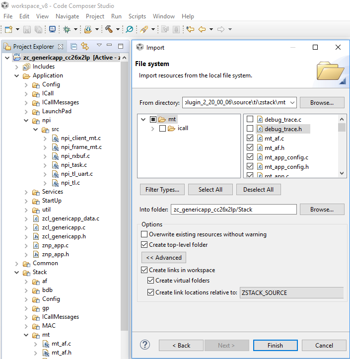
Using CCS as an example, select Project → Import → General → File System,
then browse to C:\ti\<SimpleLink SDK Path>\source\ti\zstack\mt
and select all mt files except the debug_trace files and mt_pipe files.
Place into the Stack folder and check the Create top-level folder and
Create links in workspace boxes, where locations are relative to ZSTACK_SOURCE.
When asked, do not choose to Adjust Compiler Include-Path as this creates build
errors and will be done manually in a later step.
Afterwards, do the same for all npi\src files (inc folder is not required as this
will be covered during the include options) but place the new folder inside of the
Application folder. The znp_app files can be linked to or directly copied from
C:\ti\<SimpleLink SDK Path>\examples\rtos\|DEVICE|_LAUNCHXL\zstack\common\znp_app and
placed directly into the Applications folder.
3. Include Predefined Symbols and Options
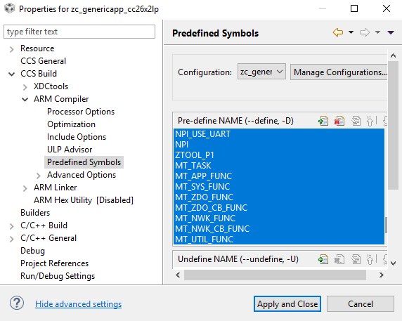
Open up the Project Properties and go to CCS Build → ARM Compiler → Predefined Symbols and add the following:
ICALL_MAX_NUM_TASKS=3NPI_USE_UARTNPIZTOOL_P1MT_TASKMT_APP_FUNCMT_SYS_FUNCMT_ZDO_FUNCMT_ZDO_CB_FUNCMT_NWK_FUNCMT_NWK_CB_FUNCMT_UTIL_FUNC
Each of which are defined in 5.2.3 OTA Server. Make sure
that BOARD_DISPLAY_USE_UART is not defined. In the Include Options tab,
add ${ZIGBEE_APPS}/common/znp_app and ${ZSTACK_SOURCE}/npi/src/inc to the
#include search paths.
4. Verify Operation
The serial configurations are set by NPITLUART_initializeTransport of npi_tl_uart.c
void NPITLUART_initializeTransport(Char *tRxBuf, Char *tTxBuf, npiCB_t npiCBack) { UART_Params params; TransportRxBuf = tRxBuf; TransportTxBuf = tTxBuf; npiTransmitCB = npiCBack; // Initialize the UART driver UART_init(); // Configure UART parameters. UART_Params_init(¶ms); params.baudRate = NPI_UART_BR; params.readDataMode = UART_DATA_BINARY; params.writeDataMode = UART_DATA_BINARY; params.dataLength = UART_LEN_8; params.stopBits = UART_STOP_ONE; params.readMode = UART_MODE_CALLBACK; params.writeMode = UART_MODE_CALLBACK; params.readEcho = UART_ECHO_OFF; params.readCallback = NPITLUART_readCallBack; params.writeCallback = NPITLUART_writeCallBack; // Open / power on the UART. uartHandle = UART_open(Board_UART0, ¶ms); //Enable Partial Reads on all subsequent UART_read() UART_control(uartHandle, UARTCC26XX_CMD_RETURN_PARTIAL_ENABLE, NULL); #if (NPI_FLOW_CTRL == 0) // This call will start repeated Uart Reads when Power Savings is disabled NPITLUART_readTransport(); #endif // NPI_FLOW_CTRL = 0 return; } by default for this sample application is:
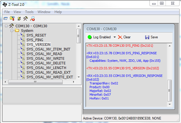
Therefore the default configuration is 115200 baud with no flow or parity, one stop bit, and 8 data bits. You can test the MT setup by opening Z-Tool and connecting to the device’s enumerated Application/UART COM Port by going to Tools → Settings → Serial Devices, double-clicking on the correct COM Port Name, and modifying the Port Settings as described above. You should then see the device recognized in the log window and be able to send a SYS_PING or SYS_VERSION message. Receiving a valid response confirms proper initialization. Please reference the Z-Stack Monitor and Test API for more information on how to utilize the MT interface.