Create a Downloadable Thread Image
The only supported out-of-box example of a downloadable image for Thread is the
oad_cli_<BOARD>_tirtos_ccs project. This is a modified version of
the cli_ftd_<BOARD>_tirtos_ccs project. We will be looking at the
differences between the two example applications as a case study for adding OAD
support to an existing project.
Changes to linker script
One of the major changes between the downloadable CLI example application and the regular CLI example is the linker script. Changes include; reserving space for the metadata headers, reserving the last page of flash, moving the CCFG, and.
To reserve the necessary memory for the image header, a memory section was
added to the flash map, this can be seen on line 94 below. As mentioned in
OAD Image Header the required size and position is fixed at the base
of the flash layout and is 0x100 bytes in size.
Another memory section is reserved for the reset vectors. To ensure that the
application’s reset vectors are placed at 0x100, this section is explicitly
placed on line 95 below. The length of that section is set at 0x100 to
ensure that more than enough room is reserved for the reset vectors.
Finally, as noted in Boot Image Manager (BIM) we need to reserve enough space for the
BIM itself. This is defined as the last page in our flash map. This reservation
can be seen by noticing that the FLASH_BULK section is 3 pages smaller than
the flash size on line 96 below. A section is also added for a debug BIM
and CCFG on line 99 below, this is used to place a pre-built BIM and CCFG.
Note
The author of this OAD example application choose to reserve the second and third to last pages of flash for NV storage. This is different than the regular CLI example. Both approaches are valid.
91 92 93 94 95 96 97 98 99 100 101 102 103 104 105 | MEMORY
{
/* Application stored in and executes from internal flash */
FLASH_IMG_HDR : origin = FLASH_BASE + 0x000 , length = 0x100
FLASH_ENTRY : origin = FLASH_BASE + 0x100 , length = 0x100
FLASH_BULK (RX) : origin = FLASH_BASE + 0x200 , length = (FLASH_SIZE - (3 * FLASH_SECTOR_SIZE) - 0x200)
// For CCS - the FLASH_NV is defined by other means
FLASH_BIM_CCFG (RX) : origin = FLASH_BIM_CCFG_BASE , length = FLASH_BIM_CCFG_SIZE
/* Application uses internal RAM for data */
SRAM (RWX) : origin = RAM_BASE, length = RAM_SIZE
/* Application can use GPRAM region as RAM if cache is disabled in the CCFG
(DEFAULT_CCFG_SIZE_AND_DIS_FLAGS.SET_CCFG_SIZE_AND_DIS_FLAGS_DIS_GPRAM = 0) */
GPRAM (RWX): origin = GPRAM_BASE, length = GPRAM_SIZE
}
|
Then the two new sections need to be filled with information. Place the OAD image header in the flash image header section. And, move the interrupt vectors into the new flash entry section. Don’t forget to rename the placements for the old flash section.
115 116 117 118 119 120 121 122 123 124 125 | GROUP > FLASH_IMG_HDR
{
.oad_image_header
}
GROUP > FLASH_ENTRY
{
.resetVecs
.intvecs
EntrySection LOAD_START(prgEntryAddr)
}
|
Remove the now unused ccfg placement. For our ti-cgt toolchain examples this
usually shows up as .ccfg : > FLASH (HIGH) in the linker
script.
Remove or change project files
Some files need to be removed from the project to allow placement to continue. Some files need to be added to the project to build the image header. And some files can be optionally added to improve the debug and development experience.
Remove the ccfg.c file from the project. This will prevent the CCFG
from being added to the final built image. The CCFG is now owned by the BIM
project, and the CC26x2 will use that CCFG.
Add the oad_image_header.c and oad_image_header.h files to your
project. These can be copied from the oad_cli_<BOARD>_tirtos_ccs project
directly. These source files define the OAD image header that is placed at the
origin of the image.
Optionally add the files bim_oad_debug_image_bim.c and
bim_oad_debug_image_bim.h files to your project. These are not required for
creating a downloadable image. These source files add a C array at the end of
flash that is a known good BIM image. This only serves to make programming and
debugging within the CCS environment easy. It may be advisable for you to look
at the BIM project, or to create your own.
Consult the main_oad.c source file in oad_cli_<BOARD>_tirtos_ccs for a
mechanism to erase the CRC metadata in the image header. This will allow you to
invalidate your running image and force BIM to reload the factory image.
Add the post-build steps to the project
Finally we need to define the post-build step that takes the *.out file to
a *.hex file and finally creating the downloadable *.bin file.
First we need to define the location of the OAD image tool. Open the project
properties by right clicking on the project in the project explorer and
selecting Properties. Then navigate to the Linked Resources page by
selecting Resource → Linked Resources. From there add a new path
variable by clicking New... as seen below.
| Name | OAD_IMAGE_TOOL |
| Location | ${COM_TI_SIMPLELINK_CC26X2_SDK_INSTALL_DIR}\tools\common\oad\bin\${OsType}\oad_image_tool |
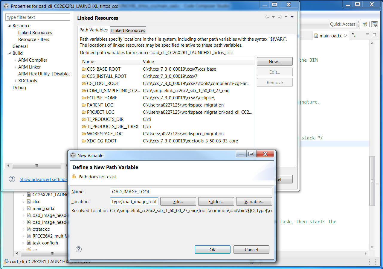
Figure 73. Defining the OAD image tool location
Note
CCS may complain that the location does not exist, this is due to the
${OsType} build variable in the path. This variable is only valid at
build time.
Finally we need to add the post-build steps to the configuration. In the
project’s Properties, navigate to the Build page by selecting Build. Then
select the Steps tab and add the following lines to the Post-build
steps text box.
${CG_TOOL_HEX} -order MS --memwidth=8 --romwidth=8 --intel -o ${ProjName}.hex ${ProjName}.out
${OAD_IMAGE_TOOL} --verbose ccs ${PROJECT_LOC}/${ConfigName} 7 -hex1 ${ProjName}.hex -o ${ProjName}_oad
This will add the two necessary steps to flatten the image into a *.hex,
and create the downloadable *.bin binary.