HCI Interface
HCI Overview
The HCI is a standardized Bluetooth interface for sending commands, receiving events, and for sending and receiving data. It is typically realized as a serial interface, using either RS232 or USB communication devices. As the name implies, the HCI is used to bridge the Host and Controller devices. Commands and Events can either be specified, or can be vendor specific for extensibility. The following sections summarize the HCI protocol, the specification defined commands and events used by BLE, and a detailed description of the vendor specific commands and events defined by Texas Instruments Inc. For complete details on the HCI as specified by the Special Interest Group (SIG), please see the Core specification [1].
Specification Interface
HCI Interface Protocol
The HCI supports four types of packets: Command Packet, Asynchronous Data Packet, Synchronous Data Packet, and Event Packet. The packet type is a one byte value that precedes the HCI packet. The packet type has the following values:
| Packet | Packet Type |
|---|---|
| Command | 0x01 |
| Asynchronous Data | 0x02 |
| Synchronous Data | 0x03 |
| Event | 0x04 |
| Extended Command | 0x09 |
The contents of each packet are shown as follows (please see section 5.4 of [1], Vol. 2, Part E for additional details).
Command Packet
The command packet is comprised of the opcode, the number of parameters, and parameters themselves.
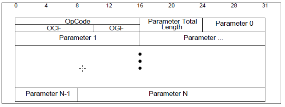
Fig. 5 Command Packet
Asynchronous Data Packet
The asynchronous data packet is comprised of the connection handle, fragmentation bits, the number of data bytes, and the data bytes themselves.
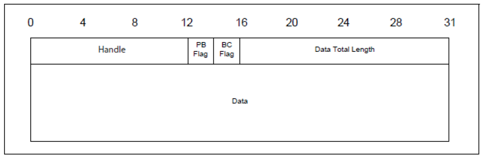
Fig. 6 Asynchronous Data Packet
Synchronous Data Packet
This synchronous data packet is not used in BLE.
Event Packet
The event packet is comprised of the event code, the number of event parameters, and the event parameters themselves.
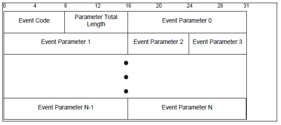
Fig. 7 Event Packet
Extended Command
This packet is used to allow more than the HCI limit of 256 bytes. It includes a two-byte length field which states the payload length:
| Offset | Description |
|---|---|
| 0 | packet type (0x09) |
| 1 | LSB opcode |
| 2 | MSB opcode |
| 3 | LSB payload length |
| 4 | MSB payload length |
| 5..(length-3) | Payload |
See each individual command for payload formatting.
HCI Commands
HCI commands use a 16-bit opcode for identification. The opcode is subdivided into two parts: a 10-bit Opcode Command Field (OCF) and a 6-bit Opcode Group Field (OGF).

Fig. 8 HCI Command Opcode
The OGF values are defined by the Bluetooth (BT) Core specification. The LE specification has its own OGF value. Also, there is an escape OGF value so that vendor specific OCF codes can be used. The following OGF values are valid for BLE: # Link Control Commands: 1 # Link Policy Commands: 2 # Controller and Baseband Commands: 3 # Informational Parameters: 4 # Status Parameters: 5 # Testing Commands: 6 # LE Only Commands: 8 # Vendor Specific Commands: 63
The following table, Table 2, lists all specification LE HCI commands and their opcodes. Note that while all commands can be sent by the application processor to the Network Processor using HCI, not all events will be returned as they will be trapped and possibly discarded by the Host layer of the BLE Stack. Therefore, it is not possible to support an external BLE Host in the Network Processor configuration. Network Processor based designs should use the respective Vendor Extension commands detailed in the following sections to implement an off-chip application.
| LE Commands | OGF | OCF | Opcdoe |
|---|---|---|---|
| LE Set Event Mask | 8 | 1 | 0x2001 |
| LE Read Buffer Size | 8 | 2 | 0x2002 |
| LE Read Local Supported Features | 8 | 3 | 0x2003 |
| LE Set Random Address | 8 | 5 | 0x2005 |
| LE Set Advertising Parameters | 8 | 6 | 0x2006 |
| LE Read Advertising Channel TX Power | 8 | 7 | 0x2007 |
| LE Set Advertising Data | 8 | 8 | 0x2008 |
| LE Set Scan Response Data | 8 | 9 | 0x2009 |
| LE Set Advertise Enable | 8 | 10 | 0x200A |
| LE Set Scan Parameters | 8 | 11 | 0x200B |
| LE Set Scan Enable | 8 | 12 | 0x200C |
| LE Create Connection | 8 | 13 | 0x200D |
| LE Create Connection Cancel | 8 | 14 | 0x200E |
| LE Read White List Size | 8 | 15 | 0x200F |
| LE Clear White Lis | 8 | 16 | 0x2010 |
| LE Add Device To White List | 8 | 17 | 0x2011 |
| LE Remove Device From White List | 8 | 18 | 0x2012 |
| LE Connection Update | 8 | 19 | 0x2013 |
| LE Set Host Channel Classification | 8 | 20 | 0x2014 |
| LE Read Channel Map | 8 | 21 | 0x2015 |
| LE Read Remote Used Features | 8 | 22 | 0x2016 |
| LE Encrypt | 8 | 23 | 0x2017 |
| LE Rand | 8 | 24 | 0x2018 |
| LE Start Encryption | 8 | 25 | 0x2019 |
| LE Long Term Key Requested Reply | 8 | 26 | 0x201A |
| LE Long Term Key Requested Negative Reply | 8 | 27 | 0x201B |
| LE Read Supported States | 8 | 28 | 0x201C |
| LE Receiver Test | 8 | 29 | 0x201D |
| LE Transmitter Test | 8 | 30 | 0x201E |
| LE Test End Command | 8 | 31 | 0x201F |
| LE Remote Connection Parameter Request Reply | 8 | 32 | 0x2020 |
| LE Remote Connection Parameter Request Negative Reply | 8 | 33 | 0x2021 |
| LE Set Data Length | 8 | 34 | 0x2022 |
| LE Read Suggested Default Data Length | 8 | 35 | 0x2023 |
| LE Write Suggested Default Data Length | 8 | 36 | 0x2024 |
| LE Read Local P256 Public Key 37 0x2025 LE Generate DHKey | 8 | 38 | 0x2026 |
| LE Add Device to Resolving List | 8 | 39 | 0x2027 |
| LE Remove Device from Resolving List | 8 | 40 | 0x2028 |
| LE Clear Resolving List | 8 | 41 | 0x2029 |
| LE Read Resolving List Size | 8 | 42 | 0x202A |
| LE Read Peer Resolvable Address | 8 | 43 | 0x202B |
| LE Read Local Resolvable Address | 8 | 44 | 0x202C |
| LE Set Address Resolution Enable | 8 | 45 | 0x202D |
| LE Set Resolvable Private Address Timeout | 8 | 46 | 0x202E |
| LE Read Maximum Data Length | 8 | 47 | 0x202F |
| BT Commands for LE | OGF | OCF | Opcode |
|---|---|---|---|
| Disconnect | 1 | 6 | 0x0406 |
| Read Remote Version Information | 1 | 29 | 0x041D |
| Set Event Mask | 3 | 1 | 0x0C01 |
| Reset | 3 | 3 | 0x0C03 |
| Read Transmit Power Level | 3 | 45 | 0x0C2D |
| Set Controller To Host Flow Control (optional) | 3 | 49 | 0x0C31 |
| Host Buffer Size (optional) | 3 | 51 | 0x0C33 |
| Host Number Of Completed Packets (optional) | 3 | 53 | 0x0C35 |
| Set Event Mask Page | 3 | 63 | 0x0C63 |
| Read Authenticated Payload Timeout | 4 | 123 | 0x0C7B |
| Write Authenticated Payload Timeout | 4 | 124 | 0x0C7C |
| Read Local Version Information | 4 | 1 | 0x1001 |
| Read Local Supported Commands (optional) | 4 | 2 | 0x1002 |
| Read Local Supported Features | 4 | 3 | 0x1003 |
| Read BD_ADDR | 4 | 9 | 0x1009 |
| Read RSSI | 5 | 5 | 0x1405 |
HCI Events
HCI events use an 8-bit event code. All event codes are unique for BT and BLE. Only event code 255 is reserved for vendor specific events. There is only one event code for all LE events. The first event parameter is used as the subevent code to distinguish the LE event types.
The following table lists all the BLE events and their event codes, and subevent codes when applicable:
| LE Events | Event Code | Subevent Code |
|---|---|---|
| LE Connection Complete | 0x3E | 0x01 |
| LE Advertising Report | 0x3E | 0x02 |
| LE Connection Update Complete | 0x3E | 0x03 |
| LE Read Remote Used Features Complete | 0x3E | 0x04 |
| LE Long Term Key Requested | 0x3E | 0x05 |
| LE Remote Connection Parameter Request | 0x3E | 0x06 |
| LE Data Length Change | 0x3E | 0x07 |
| LE Read Local P256 Public Key Complete | 0x3E | 0x08 |
| LE Generate DHKey Complete | 0x3E | 0x09 |
| LE Enhanced Connection Complete | 0x3E | 0x0A |
| LE Direct Advertising Report | 0x3E | 0x0B |
| BT Events | Event Code |
|---|---|
| Disconnection Complete | 0x05 |
| Encryption Change | 0x08 |
| Read Remote Version Information Complete | 0x0C |
| Command Complete | 0x0E |
| Command Status | 0x0F |
| Hardware Error (optional) | 0x10 |
| Number Of Completed Packets | 0x13 |
| Data Buffer Overflow | 0x1A |
| Encryption Key Refresh Complete | 0x30 |
| Authenticated Payload Timeout Expired | 0x57 |
Vendor Specific Interface
As mentioned, vendors can specify their own HCI commands and events by using the predefined vendor specific opcode and vendor specific event code.
Vendor Specific Commands
A vendor specific opcode is indicated by an OGF value of 63. The vendor can use the remaining 10 bits (i.e. the OCF) as they like. TI defines its vendor specific OCF values by subdividing the 10 bits into a 3 MSB Command Subgroup (CSG) and a 7 LSB Command (CMD). The CSG is used by the HCI to route the commands to a designated subsystem within the BLE stack. In this way, vendor specific commands can be specified for any BLE stack layer.

Fig. 9 HCI Vendor Specific Command Opcode, CSG=0..6
The Command Subgroups are defined as follows:
| CSG | Subgroup |
|---|---|
| 0 | HCI |
| 1 | L2CAP |
| 2 | ATT |
| 3 | GATT |
| 4 | GAP |
| 5 | UTIL |
| 6 | Reserved |
| 7 | User Profile |
For Command Subgroups 0 to 6, the remaining 7 bits of Command provide up to 128 commands for each subgroup. For Subgroup 7, the remaining 7 bits specify one of 128 profiles and indicates that the subsequent byte is to be used as the command for that particular profile (i.e. up to 256 commands per profile).
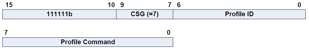
Fig. 10 HCI Vendor Specific Command Opcode, CSG=7
The following table lists all TI-specific HCI commands:
| Vendor Specific Command | OGF | CSG | CMD | Opcode |
|---|---|---|---|---|
| HCI_EXT_SetRxGainCmd | 63 | 0 | 0 | 0xFC00 |
| HCI_EXT_SetTxPowerCmd | 63 | 0 | 1 | 0xFC01 |
| HCI_EXT_OnePktPerEvtCmd | 63 | 0 | 2 | 0xFC02 |
| HCI_EXT_ClkDivideOnHaltCmd | 63 | 0 | 3 | 0xFC03 |
| HCI_EXT_DeclareNvUsageCmd | 63 | 0 | 4 | 0xFC04 |
| HCI_EXT_DecryptCmd | 63 | 0 | 5 | 0xFC05 |
| HCI_EXT_SetLocalSupportedFeaturesCmd | 63 | 0 | 6 | 0xFC06 |
| HCI_EXT_SetFastTxRespTimeCmd | 63 | 0 | 7 | 0xFC07 |
| HCI_EXT_ModemTestTxCmd | 63 | 0 | 8 | 0xFC08 |
| HCI_EXT_ModemHopTestTxCmd | 63 | 0 | 9 | 0xFC09 |
| HCI_EXT_ModemTestRxCmd | 63 | 0 | 10 | 0xFC0A |
| HCI_EXT_EndModemTestCmd | 63 | 0 | 11 | 0xFC0B |
| HCI_EXT_SetBDADDRCmd | 63 | 0 | 12 | 0xFC0C |
| HCI_EXT_SetSCACmd | 63 | 0 | 13 | 0xFC0D |
| HCI_EXT_EnablePTMCmd | 63 | 0 | 14 | 0xFC0E |
| HCI_EXT_SetFreqTuneCmd | 63 | 0 | 15 | 0xFC0F |
| HCI_EXT_SaveFreqTuneCmd | 63 | 0 | 16 | 0xFC10 |
| HCI_EXT_SetMaxDtmTxPowerCmd | 63 | 0 | 17 | 0xFC11 |
| HCI_EXT_MapPmIoPortCmd | 63 | 0 | 18 | 0xFC12 |
| HCI_EXT_DisconnectImmedCmd | 63 | 0 | 19 | 0xFC13 |
| HCI_EXT_PacketErrorRateCmd | 63 | 0 | 20 | 0xFC14 |
| HCI_EXT_PERbyChanCmd | 63 | 0 | 21 | 0xFC15 |
| HCI_EXT_ExtendRfRangeCmd | 63 | 0 | 22 | 0xFC16 |
| HCI_EXT_AdvEventNoticeCmd | 63 | 0 | 23 | 0xFC17 |
| HCI_EXT_ConnEventNoticeCmd | 63 | 0 | 24 | 0xFC18 |
| HCI_EXT_HaltDuringRfCmd | 63 | 0 | 25 | 0xFC19 |
| HCI_EXT_SetSlaveLatencyOverrideCmd | 63 | 0 | 26 | 0xFC1A |
| HCI_EXT_BuildRevisionCmd | 63 | 0 | 27 | 0xFC1B |
| HCI_EXT_DelaySleepCmd | 63 | 0 | 28 | 0xFC1C |
| HCI_EXT_ResetSystemCmd | 63 | 0 | 29 | 0xFC1D |
| HCI_EXT_OverlappedProcessingCmd | 63 | 0 | 30 | 0xFC1E |
| HCI_EXT_NumComplPktsLimitCmd | 63 | 0 | 31 | 0xFC1F |
| HCI_EXT_GetConnInfoCmd | 63 | 0 | 32 | 0xFC20 |
| HCI_EXT_SetMaxDataLenCmd | 63 | 0 | 33 | 0xFC21 |
| HCI_EXT_ScanEventNoticeCmd | 63 | 0 | 34 | 0xFC22 |
| HCI_EXT_ScanReqRptCmd | 63 | 0 | 35 | 0xFC23 |
| HCI_EXT_SetDtmTxPktCntCmd | 63 | 0 | 36 | 0xFC24 |
| HCI_EXT_EnhancedModemTestTxCmd | 63 | 0 | 39 | 0xFC27 |
| HCI_EXT_EnhancedModemHopTestTxCmd | 63 | 0 | 40 | 0xFC28 |
| HCI_EXT_EnhancedModemTestRxCmd | 63 | 0 | 41 | 0xFC29 |
| HCI_EXT_LLTestModeCmd | 63 | 0 | 112 | 0xFC70 |
| L2CAP_DisconnectReq | 63 | 1 | 6 | 0xFC86 |
| L2CAP_InfoReq | 63 | 1 | 10 | 0xFC8A |
| L2CAP_ConnParamUpdateReq | 63 | 1 | 18 | 0xFC92 |
| L2CAP_ConnectReq | 63 | 1 | 20 | 0xFC94 |
| L2CAP_ConnectRsp | 63 | 1 | 21 | 0xFC95 |
| L2CAP_FlowCtrlCredit | 63 | 1 | 22 | 0xFC96 |
| L2CAP_SendData | 63 | 1 | 112 | 0xFCF0 |
| L2CAP_RegisterPsm | 63 | 1 | 113 | 0xFCF1 |
| L2CAP_DeregisterPsm | 63 | 1 | 114 | 0xFCF2 |
| L2CAP_PsmInfo | 63 | 1 | 115 | 0xFCF3 |
| L2CAP_PsmChannels | 63 | 1 | 116 | 0xFCF4 |
| L2CAP_ChannelInfo | 63 | 1 | 117 | 0xFCF5 |
| ATT_ErrorRsp | 63 | 2 | 1 | 0xFD01 |
| ATT_ExchangeMTUReq | 63 | 2 | 2 | 0xFD02 |
| ATT_ExchangeMTURsp | 63 | 2 | 3 | 0xFD03 |
| ATT_FindInfoReq | 63 | 2 | 4 | 0xFD04 |
| ATT_FindInfoRsp | 63 | 2 | 5 | 0xFD05 |
| ATT_FindByTypeValueReq | 63 | 2 | 6 | 0xFD06 |
| ATT_FindByTypeValueRsp | 63 | 2 | 7 | 0xFD07 |
| ATT_ReadByTypeReq | 63 | 2 | 8 | 0xFD08 |
| ATT_ReadByTypeRsp | 63 | 2 | 9 | 0xFD09 |
| ATT_ReadReq | 63 | 2 | 10 | 0xFD0A |
| ATT_ReadRsp | 63 | 2 | 11 | 0xFD0B |
| ATT_ReadBlobReq | 63 | 2 | 12 | 0xFD0C |
| ATT_ReadBlobRsp | 63 | 2 | 13 | 0xFD0D |
| ATT_ReadMultiReq | 63 | 2 | 14 | 0xFD0E |
| ATT_ReadMultiRsp | 63 | 2 | 15 | 0xFD0F |
| ATT_ReadByGrpTypeReq | 63 | 2 | 16 | 0xFD10 |
| ATT_ReadByGrpTypeRsp | 63 | 2 | 17 | 0xFD11 |
| ATT_WriteReq | 63 | 2 | 18 | 0xFD12 |
| ATT_WriteRsp | 63 | 2 | 19 | 0xFD13 |
| ATT_PrepareWriteReq | 63 | 2 | 22 | 0xFD16 |
| ATT_PrepareWriteRsp | 63 | 2 | 23 | 0xFD17 |
| ATT_ExecuteWriteReq | 63 | 2 | 24 | 0xFD18 |
| ATT_ExecuteWriteRsp | 63 | 2 | 25 | 0xFD19 |
| ATT_HandleValueNoti | 63 | 2 | 27 | 0xFD1B |
| ATT_HandleValueInd | 63 | 2 | 29 | 0xFD1D |
| ATT_HandleValueCfm | 63 | 2 | 30 | 0xFD1E |
| GATT_ExchangeMTU | 63 | 3 | 2 | 0xFD82 |
| GATT_DiscAllCharDescs | 63 | 3 | 4 | 0xFD84 |
| GATT_DiscPrimaryServiceByUUID | 63 | 3 | 6 | 0xFD86 |
| GATT_DiscCharsByUUID | 63 | 3 | 8 | 0xFD88 |
| GATT_ReadCharValue | 63 | 3 | 10 | 0xFD8A |
| GATT_ReadLongCharValue | 63 | 3 | 12 | 0xFD8C |
| GATT_ReadMultiCharValues | 63 | 3 | 14 | 0xFD8E |
| GATT_DiscAllPrimaryServices | 63 | 3 | 16 | 0xFD90 |
| GATT_WriteCharValue | 63 | 3 | 18 | 0xFD92 |
| GATT_WriteLongCharValue | 63 | 3 | 22 | 0xFD96 |
| GATT_Notification | 63 | 3 | 27 | 0xFD9B |
| GATT_Indication | 63 | 3 | 29 | 0xFD9D |
| GATT_FindIncludedServices | 63 | 3 | 48 | 0xFDB0 |
| GATT_DiscAllChars | 63 | 3 | 50 | 0xFDB2 |
| GATT_ReadUsingCharUUID | 63 | 3 | 52 | 0xFDB4 |
| GATT_WriteNoRsp | 63 | 3 | 54 | 0xFDB6 |
| GATT_SignedWriteNoRsp | 63 | 3 | 56 | 0xFDB8 |
| GATT_ReliableWrites | 63 | 3 | 58 | 0xFDBA |
| GATT_ReadCharDesc | 63 | 3 | 60 | 0xFDBC |
| GATT_ReadLongCharDesc | 63 | 3 | 62 | 0xFDBE |
| GATT_WriteCharDesc | 63 | 3 | 64 | 0xFDC0 |
| GATT_WriteLongCharDesc | 63 | 3 | 66 | 0xFDC2 |
| GATT_AddService | 63 | 3 | 124 | 0xFDFC |
| GATT_DelService | 63 | 3 | 125 | 0xFDFD |
| GATT_AddAttribute | 63 | 3 | 126 | 0xFDFE |
| GAP_DeviceInit | 63 | 4 | 0 | 0xFE00 |
| GAP_TerminateLinkReq | 63 | 4 | 10 | 0xFE0A |
| GAP_Authenticate | 63 | 4 | 11 | 0xFE0B |
| GAP_PasskeyUpdate | 63 | 4 | 12 | 0xFE0C |
| GAP_SlaveSecurityRequest | 63 | 4 | 13 | 0xFE0D |
| GAP_Signable | 63 | 4 | 14 | 0xFE0E |
| GAP_Bond | 63 | 4 | 15 | 0xFE0F |
| GAP_TerminateAuth | 63 | 4 | 16 | 0xFE10 |
| GAP_UpdateLinkParamReq | 63 | 4 | 17 | 0xFE11 |
| GAP_UpdateLinkParamReqReply | 63 | 4 | 18 | 0xFE12 |
| GapConfig_SetParameter | 63 | 4 | 47 | 0xFE2F |
| GAP_SetParamValue | 63 | 4 | 48 | 0xFE30 |
| GAP_GetParamValue | 63 | 4 | 49 | 0xFE31 |
| GAPBondMgr_SetParameter | 63 | 4 | 54 | 0xFE36 |
| GAPBondMgr_GetParameter | 63 | 4 | 55 | 0xFE37 |
| GAPBondMgr_ServiceChangeInd | 63 | 4 | 56 | 0xFE38 |
| SM_RegisterTask | 63 | 4 | 57 | 0xFE39 |
| SM_GetEccKeys | 63 | 4 | 58 | 0xFE3A |
| SM_GetDHKey | 63 | 4 | 59 | 0xFE3B |
| SM_GetScConfirmOob | 63 | 4 | 60 | 0xFE3C |
| GapAdv_create | 63 | 4 | 62 | 0xFE3E |
| GapAdv_enable | 63 | 4 | 63 | 0xFE3F |
| GAPBondMgr_PasscodeRsp | 63 | 4 | 74 | 0xFE4A |
| GapAdv_disable | 63 | 4 | 64 | 0xFE40 |
| GapAdv_destroy | 63 | 4 | 65 | 0xFE41 |
| GapAdv_setParam | 63 | 4 | 66 | 0xFE42 |
| GapAdv_getParam | 63 | 4 | 67 | 0xFE43 |
| GapAdv_loadData | 63 | 4 | 68 | 0xFE44 |
| GapAdv_setEventMask | 63 | 4 | 69 | 0xFE45 |
| GAPBondMgr_Pair | 63 | 4 | 72 | 0xFE48 |
| GAPBondMgr_FindAddr | 63 | 4 | 73 | 0xFE49 |
| GapScan_enable | 63 | 4 | 81 | 0xFE51 |
| GapScan_disable | 63 | 4 | 82 | 0xFE52 |
| GapScan_setPhyParams | 63 | 4 | 83 | 0xFE53 |
| GapScan_getPhyParams | 63 | 4 | 84 | 0xFE54 |
| GapScan_setParam | 63 | 4 | 85 | 0xFE55 |
| GapScan_getParam | 63 | 4 | 86 | 0xFE56 |
| GapScan_setEventMask | 63 | 4 | 87 | 0xFE57 |
| GapScan_getAdvReport | 63 | 4 | 88 | 0xFE58 |
| GapInit_setPhyParam | 63 | 4 | 96 | 0xFE60 |
| GapInit_getPhyParam | 63 | 4 | 97 | 0xFE61 |
| GapInit_connect | 63 | 4 | 98 | 0xFE62 |
| GapInit_connectWl | 63 | 4 | 99 | 0xFE63 |
| GapInit_cancelConnect | 63 | 4 | 100 | 0xFE64 |
| UTIL_Reserved | 63 | 5 | 0 | 0xFE80 |
| UTIL_NV_Read | 63 | 5 | 1 | 0xFE81 |
| UTIL_NV_Write | 63 | 5 | 2 | 0xFE82 |
| UTIL_ForceBoot | 63 | 5 | 3 | 0xFE83 |
| UTIL_BuildRevision | 63 | 5 | 4 | 0xFE84 |
| UTIL_GetMemStats | 63 | 5 | 7 | 0xFE87 |
Vendor Specific Events
A vendor specific event code is indicated by a value of 255. The vendor must then use event parameters (following the length byte) to specify vendor specific events. TI defines the following two bytes as the Event Opcode.
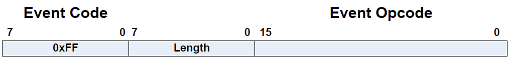
The Event Opcode was chosen to mirror the Command Opcode by dividing it into two parts: a 6 bit Event Opcode Group Field (EOGF), and a 10 bit Event Opcode Event Field (EOEF).

The EOEF is again chosen to mirror the Command OCF by dividing it into two parts: the Event Subgroup (ESG) and the Event.

The EOGF is defined as follows:
| EOGF | Group |
|---|---|
| 0 | Embedded Opcode |
| 1 | Core Opcode |
| 2 | Profile Request |
| 3 | Profile Response |
| 4-63 | Reserved |
The ESG is defined as in Table 4. The Events are as defined in the following table. Please note that the value of the Events cannot be less than 0x400 as the first 1024 values are reserved. The reason for this has to do with Client/Server Request/Response Tunneling, which is described in the following section. Tunneling requires embedding Command Opcodes in HCI Events. When this is done, the EOGF is zero, and the remaining 10 bits is the Command Opcode. In order to prevent Command and Event Opcode overlap, the first 1024 values are reserved in the Event Opcode space. Also note that the Event Code (EC) is always 0xFF since normally only Controller events are returned via the HCI.
| Vendor Specific Event | EC | EOGF | ESG | Event | Opcode |
|---|---|---|---|---|---|
| HCI_EXT_SetRxGainDone | 0xFF | 1 | 0 | 0 | 0x0400 |
| HCI_EXT_SetTxPowerDone | 0xFF | 1 | 0 | 1 | 0x0401 |
| HCI_EXT_OnePacketPerEventDone | 0xFF | 1 | 0 | 2 | 0x0402 |
| HCI_EXT_DecryptCommandDone | 0xFF | 1 | 0 | 5 | 0x0405 |
| HCI_EXT_WriteLocalFeatureSupportDone | 0xFF | 1 | 0 | 6 | 0x0406 |
| HCI_EXT_SetFastTxResponseTimeDone | 0xFF | 1 | 0 | 7 | 0x0407 |
| HCI_EXT_ModemTestTxDone | 0xFF | 1 | 0 | 8 | 0x0408 |
| HCI_EXT_ModemHopTestTxDone | 0xFF | 1 | 0 | 9 | 0x0409 |
| HCI_EXT_ModemTestRxDone | 0xFF | 1 | 0 | 10 | 0x040A |
| HCI_EXT_EndModemTestDone | 0xFF | 1 | 0 | 11 | 0x040B |
| HCI_EXT_SetBDADDRDone | 0xFF | 1 | 0 | 12 | 0x040C |
| HCI_EXT_SetSCADone | 0xFF | 1 | 0 | 13 | 0x040D |
| HCI_EXT_EnablePTMDone | 0xFF | 1 | 0 | 14 | 0x040E |
| HCI_EXT_SetMaxDtmTxPowerDone | 0xFF | 1 | 0 | 17 | 0x0411 |
| HCI_EXT_MapPmIoPortDone | 0xFF | 1 | 0 | 18 | 0x0412 |
| HCI_EXT_DisconnectImmedDone | 0xFF | 1 | 0 | 19 | 0x0413 |
| HCI_EXT_PER | 0xFF | 1 | 0 | 20 | 0x0414 |
| HCI_EXT_PerByChanDone | 0xFF | 1 | 0 | 21 | 0x0415 |
| HCI_EXT_AdvEventNoticeDone | 0xFF | 1 | 0 | 23 | 0x0417 |
| HCI_EXT_ConnEventNoticeDone | 0xFF | 1 | 0 | 24 | 0x0418 |
| HCI_EXT_OverrideSLDone | 0xFF | 1 | 0 | 26 | 0x041A |
| HCI_EXT_BuildRevisionDone | 0xFF | 1 | 0 | 27 | 0x041B |
| HCI_EXT_ResetSystemDone | 0xFF | 1 | 0 | 29 | 0x041D |
| HCI_EXT_NumComplPktsLimitDone | 0xFF | 1 | 0 | 31 | 0x041F |
| HCI_EXT_GetConnInfoDone | 0xFF | 1 | 0 | 32 | 0x0420 |
| HCI_EXT_SetMaxDataLengthDone | 0xFF | 1 | 0 | 33 | 0x0421 |
| HCI_EXT_ScanEventNoticeDone | 0xFF | 1 | 0 | 34 | 0x0422 |
| HCI_EXT_ScanReqRptCmdDone | 0xFF | 1 | 0 | 35 | 0x0423 |
| HCI_EXT_SetDtmTxPktCntDone | 0xFF | 1 | 0 | 36 | 0x0424 |
| HCI_EXT_LE_ADV_EVENT | 0xFF | 1 | 0 | 37 | 0x0425 |
| HCI_EXT_LE_SCAN_EVENT | 0xFF | 1 | 0 | 38 | 0x0426 |
| HCI_EXT_EnhancedModemTestTxDone | 0xFF | 1 | 0 | 39 | 0x0427 |
| HCI_EXT_EnhancedModemHopTestTxDone | 0xFF | 1 | 0 | 40 | 0x0428 |
| HCI_EXT_EnhancedModemTestRxDone | 0xFF | 1 | 0 | 41 | 0x0429 |
| HCI_EXT_LLTestModeDone | 0xFF | 1 | 0 | 112 | 0x0470 |
| L2CAP_CmdReject | 0xFF | 1 | 1 | 1 | 0x0481 |
| L2CAP_InfoRsp | 0xFF | 1 | 1 | 11 | 0x048B |
| L2CAP_ConnParamUpdateRsp | 0xFF | 1 | 1 | 19 | 0x0493 |
| L2CAP_ConnectReq | 0xFF | 1 | 1 | 20 | 0x0494 |
| L2CAP_ChannelEstablished | 0xFF | 1 | 1 | 96 | 0x04E0 |
| L2CAP_ChannelTerminated | 0xFF | 1 | 1 | 97 | 0x04E1 |
| L2CAP_OutOfCredit | 0xFF | 1 | 1 | 98 | 0x04E2 |
| L2CAP_PeerCreditThreshold | 0xFF | 1 | 1 | 99 | 0x04E3 |
| L2CAP_SendSduDone | 0xFF | 1 | 1 | 100 | 0x04E4 |
| L2CAP_SendData | 0xFF | 1 | 1 | 112 | 0x04F0 |
| ATT_ErrorRsp | 0xFF | 1 | 2 | 1 | 0x0501 |
| ATT_ExchangeMTUReq | 0xFF | 1 | 2 | 2 | 0x0502 |
| ATT_ExchangeMTURsp | 0xFF | 1 | 2 | 3 | 0x0503 |
| ATT_FindInfoReq | 0xFF | 1 | 2 | 4 | 0x0504 |
| ATT_FindInfoRsp | 0xFF | 1 | 2 | 5 | 0x0505 |
| ATT_FindByTypeValueReq | 0xFF | 1 | 2 | 6 | 0x0506 |
| ATT_FindByTypeValueRsp | 0xFF | 1 | 2 | 7 | 0x0507 |
| ATT_ReadByTypeReq | 0xFF | 1 | 2 | 8 | 0x0508 |
| ATT_ReadByTypeRsp | 0xFF | 1 | 2 | 9 | 0x0509 |
| ATT_ReadReq | 0xFF | 1 | 2 | 10 | 0x050A |
| ATT_ReadRsp | 0xFF | 1 | 2 | 11 | 0x050B |
| ATT_ReadBlobReq | 0xFF | 1 | 2 | 12 | 0x050C |
| ATT_ReadBlobRsp | 0xFF | 1 | 2 | 13 | 0x050D |
| ATT_ReadMultiReq | 0xFF | 1 | 2 | 14 | 0x050E |
| ATT_ReadMultiRsp | 0xFF | 1 | 2 | 15 | 0x050F |
| ATT_ReadByGrpTypeReq | 0xFF | 1 | 2 | 16 | 0x0510 |
| ATT_ReadByGrpTypeRsp | 0xFF | 1 | 2 | 17 | 0x0511 |
| ATT_WriteReq | 0xFF | 1 | 2 | 18 | 0x0512 |
| ATT_WriteRsp | 0xFF | 1 | 2 | 19 | 0x0513 |
| ATT_PrepareWriteReq | 0xFF | 1 | 2 | 22 | 0x0516 |
| ATT_PrepareWriteRsp | 0xFF | 1 | 2 | 23 | 0x0517 |
| ATT_ExecuteWriteReq | 0xFF | 1 | 2 | 24 | 0x0518 |
| ATT_ExecuteWriteRsp | 0xFF | 1 | 2 | 25 | 0x0519 |
| ATT_HandleValueNoti | 0xFF | 1 | 2 | 27 | 0x051B |
| ATT_HandleValueInd | 0xFF | 1 | 2 | 29 | 0x051D |
| ATT_HandleValueCfm | 0xFF | 1 | 2 | 30 | 0x051E |
| ATT_FlowCtrlViolatedEvt_t | 0xFF | 1 | 2 | 126 | 0x057E |
| ATT_MtuUpdatedEvt | 0xFF | 1 | 2 | 127 | 0x057F |
| GATT_ClientCharCfgUpdated | 0xFF | 1 | 3 | 0 | 0x0580 |
| GAP_DeviceInitDone | 0xFF | 1 | 4 | 0 | 0x0600 |
| GAP_LinkEstablished | 0xFF | 1 | 4 | 5 | 0x0605 |
| GAP_LinkTerminated | 0xFF | 1 | 4 | 6 | 0x0606 |
| GAP_LinkParamUpdate | 0xFF | 1 | 4 | 7 | 0x0607 |
| GAP_SignatureUpdated | 0xFF | 1 | 4 | 9 | 0x0609 |
| GAP_AuthenticationComplete | 0xFF | 1 | 4 | 10 | 0x060A |
| GAP_PasskeyNeeded | 0xFF | 1 | 4 | 11 | 0x060B |
| GAP_SlaveRequestedSecurity | 0xFF | 1 | 4 | 12 | 0x060C |
| GAP_BondComplete | 0xFF | 1 | 4 | 14 | 0x060E |
| GAP_PairingRequested | 0xFF | 1 | 4 | 15 | 0x060F |
| SM_GetEccKeys | 0xFF | 1 | 4 | 16 | 0x0610 |
| SM_GetDHKey | 0xFF | 1 | 4 | 17 | 0x0611 |
| GAP_LinkParamUpdateRequest | 0xFF | 1 | 4 | 18 | 0x0612 |
| GAP_Advertiser/Scanner_Event | 0xFF | 1 | 4 | 19 | 0x0613 |
| GAP_ConnectingCancelled | 0xFF | 1 | 4 | 21 | 0x0615 |
| CommandStatus | 0xFF | 1 | 4 | 127 | 0x067F |
| UTIL_GetMemStats | 0xFF | 1 | 5 | 1 | 0x0681 |
| UTIL_SystemError | 0xFF | 1 | 5 | 2 | 0x0682 |
You will note that there are two EOGF values for Profiles. At this time, no profiles are defined well enough to document here. These values are defined in anticipation of not only needing large numbers of profiles and their commands, but also of needing the direction the command is travelling when embedded in an HCI Command or Event. You can see that ATT does not have this issue as these commands are already defined using even values for commands and odd values for events, and thus, direction is distinguishable. For profiles, it is not yet known how the commands and events will be defined.
Request and Response Tunneling
In the Client/Server model defined and supported by the BLE stack, the Client sends Requests to the Server and the Server sends Responses back to the Client. The Requests sent by the Client may be handled by a Server on the same device, or they may travel OTA to the Server on another device. Similarly, the Response sent by the Server may be handled by a Client on the same device, or may be sent OTA to a Client on another device from which the request came. But in either case, as long as the Requests and Responses remain within the scope of the BLE stack software (i.e. the BLE Server database is on the device), the BLE stack remains unconcerned about whether the Requests and Responses are sent/received by the same device or are from another device. Please see Fig. 14.
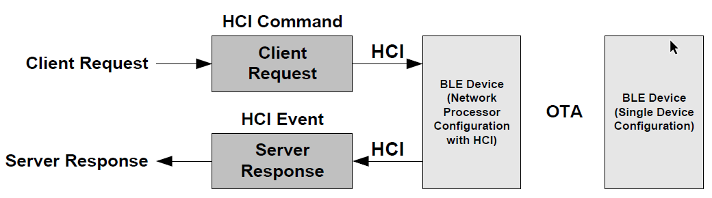
Fig. 14 Request/Response with Server Database in BLE Stack
However, when using the Network Processor Configuration with HCI such that the Server database is not located on the device, then Requests and Reponses have to be mapped into HCI Commands and Events. The HCI is specified such that only Commands are sent from the Host to the Controller, and only Events are sent from the Controller to the Host. If the Server database is located on say a PC, then when an OTA Request is received by the Server device, it must be sent to the PC via the HCI. Even though the Request started out on one end as an HCI Command, it must be provided to the remote PC as an HCI event on the other. Similarly, when the PC sends the Response on one end, which will be an HCI Event to the remote PC on the other, it must be sent to the device as an HCI Command. Thus, the Request, which starts out as an HCI Command, must be embedded in an HCI Event when received by the remote PC, and the Response, which starts out as an HCI Command, must be embedded in an HCI Event when received by the remote PC. In this way, Requests and Responses are being tunneled in HCI Commands and Events. Please see Fig. 15.
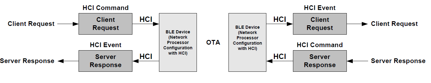
Fig. 15 Request/Response with Server Database not in BLE Stack