Developing a Bluetooth Low Energy Application
Overview
This section describes the functionality of the Bluetooth low energy protocol stack and provides a list of APIs to interface with the protocol stack. The stack project and its associated files serve to implement the Bluetooth low energy protocol stack task. This is the highest priority task in the system and it implements the Bluetooth low energy protocol stack as shown in Figure 26..
Most of the Bluetooth low energy protocol stack is object code in a single library file (TI does not provide the protocol stack source code as a matter of policy). A developer must understand the functionality of the various protocol stack layers and how they interact with the application and profiles. This section explains these layers.
Introduction
Version 4.2 of the Bluetooth specification allows for two systems of wireless technology: Basic Rate (BR: BR/EDR for Basic Rate/Enhanced Data Rate) and Bluetooth low energy. The Bluetooth low energy system was created to transmit small packets of data, while consuming significantly less power than BR/EDR devices.
The TI BLE Protocol stack supports the following 4.2 features:
- LE Secure Connections
- LE Data Length extension
- LE Privacy 1.2
The TI BLE Protocol stack also supports the following 4.1 features:
- LE L2CAP Connection-Oriented Channel Support
- LE Link Layer Topology
- LE Ping
- Slave Feature Exchange
- Connection Parameter Request
Optional features can be selectively enabled at build time. See Optimizing Bluetooth low energy Stack Memory Usage.
Bluetooth low energy Protocol Stack Basics
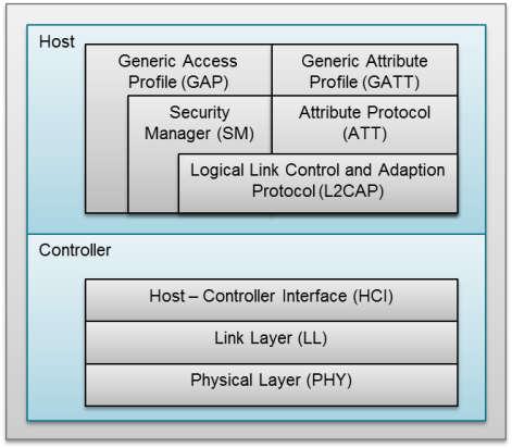
Figure 26. Bluetooth low energy Protocol Stack.
Figure 26. shows the Bluetooth low energy protocol stack architecture.
The Bluetooth low energy protocol stack (or protocol stack) consists of the controller and the host. This separation of controller and host derives from the implementation of classic Bluetooth BR/EDR devices, where the two sections are implemented separately. Any profiles and applications sit on top of the GAP and GATT layers of the protocol stack.
The physical layer (PHY) is a 1-Mbps adaptive frequency-hopping GFSK (Gaussian frequency-shift keying) radio operating in the unlicensed 2.4-GHz ISM (industrial, scientific, and medical) band.
The Generic Access Profile (GAP) controls the RF state of the device, with the device in one of five states:
- Standby
- Advertising
- Scanning
- Initiating
- Connected
Advertisers transmit data without connecting, while scanners scan for advertisers. An initiator is a device that responds to an advertiser with a request to connect. If the advertiser accepts the connection request, both the advertiser and initiator enter a connected state. When a device is connected, it connects as either master or slave. The device initiating the connection becomes the master and the device accepting the request becomes the slave.
See the BLE-Stack API Reference for HCI layer API. The HCI layer provides communication between the host and controller through a standardized interface. This layer can be implemented either through a software API or by a hardware interface such as UART, SPI, or USB. The Specification of the Bluetooth System describes Standard HCI commands and events. TI’s proprietary commands and events are specified in the TI Vendor Specific HCI Guide.
The Logical Link Control and Adaptation Layer Protocol (L2CAP) layer provides data encapsulation services to the upper layers, allowing for logical end-to-end communication of data.
The Security Manager layer defines the methods for pairing and key distribution, and provides functions for the other layers of the protocol stack to securely connect and exchange data with another device.
The Generic Access Profile (GAP) layer directly interfaces with the application and/or profiles, to handle device discovery and connection-related services for the device. GAP handles the initiation of security features.
The ATT layer allows a device to expose certain pieces of data or attributes, to another device. The Generic Attribute Profile (GATT) layer is a service framework that defines the sub-procedures for using ATT. Data communications that occur between two devices in a Bluetooth low energy connection are handled through GATT sub-procedures. The application and/or profiles will directly use GATT.
The Application
This section describes the application portion of the simple_peripheral project, which includes the following:
Note
The GAPRole Task is also part of the application project workspace, but is discussed with The Stack. The functionality of the GAPRole Task relates closely to the protocol stack.
Pre-main initialization
The main function is contained in source file main.c located in the
IDE Start-up folder. This function is the starting point at run time.
The purpose of main is to bring up the target with interrupts disabled,
drivers initialized, power management on, TI-RTOS tasks created or
constructed, and start the SYS/BIOS kernel scheduler with interrupts enabled.
The main function does not return. Main.c exists in the application
project; in other words main.c will be allocated within flash reserved for
the application.
See TI-RTOS Overview for how the application and GAPRole tasks are constructed through TI-RTOS.
Note
that the ICall module must be initialized by ICall_init and the stack task is created via ICall_createRemoteTasks.
ICall
Introduction
Indirect Call Framework (ICall) is a module that provides a mechanism for the application to interface with the Bluetooth low energy protocol stack services (that is, BLE-Stack APIs) as well as certain primitive services provided by TI-RTOS (for example, thread synchronization). ICall allows the application and protocol stack to operate efficiently, communicate, and share resources in a unified TI-RTOS environment.
The central component of the ICall architecture is the dispatcher, which facilitates the application program interface between the application and the BLE-Stack task across the dual-image boundary as well as in Library configuration. Although most ICall interactions are abstracted within the BLE-Stack APIs (for example, GAP, HCI, and so forth), the application developer must understand the underlying architecture for the BLE-Stack to operate properly in the multithreaded RTOS environment.
The ICall module source code is provided in the ICall and ICall BLE IDE folders in the application project.
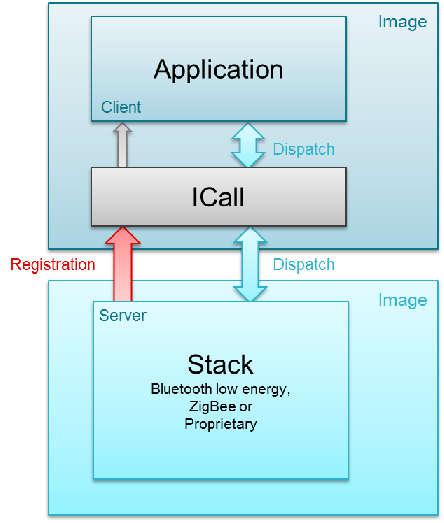
Figure 27. ICall Application – Protocol Stack Abstraction.
ICall BLE-Stack Protocol Service
As Figure 27. shows, the ICall core use case involves messaging between a server entity (that is, the BLE-Stack task) and a client entity (for example, the application task).
Note
The ICall framework is not the GATT server and client architecture, as defined by the Bluetooth Low Energy protocol.
The reasoning for this architecture is as follows:
- To enable independent updating of the application and Bluetooth Low Energy protocol stack
- To maintain API consistency as software is ported from legacy platforms (that is, OSAL for the CC254x) to TI-RTOS of the CC13x0.
The ICall BLE-Stack service serves as the application interface to BLE-Stack APIs. When a BLE-Stack API is called by the application internally, the ICall module routes (that is, dispatches) the command to the BLE-Stack and routes messages from the BLE-Stack to the application when appropriate.
Because the ICall module is part of the application project, the application task can access ICall with direct function calls. Because the BLE-Stack executes at the highest priority, the application task blocks until the response is received. Certain protocol stack APIs may respond immediately, but the application thread blocks as the API is dispatched to the BLE-Stack through ICall. Other BLE-Stack APIs may also respond asynchronously to the application through ICall (for example, event updates) with the response sent to the event handler of the application task.
ICall Primitive Service
ICall includes a primitive service that abstracts various operating system-related functions. Due to shared resources and to maintain interprocess communication, the application must use the following ICall primitive service functions:
- Messaging and Thread Synchronization
- Heap Allocation and Management
Some of these are abstracted to Util functions (see the relevant module in TI-RTOS Overview).
Messaging and Thread Synchronization
The Messaging and Thread Synchronization functions provided by ICall enable an application to communicate with the BLE-Stack in the multithreaded TI-RTOS environment.
In ICall, messaging between two tasks occurs by sending a block of message from one thread to the other through a message queue. The sender allocates a memory block, writes the content of the message into the memory block, and then sends (that is, enqueues) the memory block to the recipient. Notification of message delivery occurs using a event flag. The receiver wakes up on the event flag post, copies the message memory block (or blocks), processes the message, and returns (frees) the memory block to the heap.
The stack uses ICall for notifying and sending messages to the application. ICall delivers these service messages, the application task receives them, and the messages are processed in the context of the application.
Heap Allocation and Management
ICall provides the application with global heap APIs for dynamic
memory allocation. The size of the ICall heap is configured with the
HEAPMGR_SIZE preprocessor-defined symbol in the application
project. See Dynamic Memory Allocation for more details on managing dynamic
memory. ICall uses this heap for all protocol stack messaging and to
obtain memory for other ICall services. TI recommends that the
application uses these ICall APIs to allocate dynamic memory.
ICall Initialization and Registration
To instantiate and initialize the ICall service, the application must call the functions in in the snippet below in main() before starting the TI-RTOS kernel scheduler:
Calling ICall_init initializes the ICall primitive service (for
example, heap manager) and framework. Calling
ICall_createRemoteTasks creates but does not start the BLE-Stack
task. Before using ICall protocol
services, the server and client must enroll and register with ICall.
The server enrolls a service, which is defined at build time.
Service function handler registration uses a globally defined unique
identifier for each service. For example, Bluetooth low energy uses
ICALL_SERVICE_CLASS_BLE for receiving BLE-Stack task messages through
ICall.
To enroll the BLE-Stack service (server) with ICall in osal_icall_ble.c see the snippet below
The registration mechanism is used by the client to send and/or receive messages through the ICall dispatcher.
For a client (for example, application task) to use the BLE-Stack APIs,
the client must first register its task with
ICall. This registration usually occurs in the task initialization
function of the application. The snippet below is an example from
simple_peripheral_init in simple_peripheral.c
The application supplies the selfEntity and syncEvent inputs. These inputs are initialized for the task of the client (for example, application) when the ICall_registerApp returns are initialized. These objects are subsequently used by ICall to facilitate messaging between the application and server tasks. The syncEvent argument represents the Events Module handle for signaling and the selfEntity represents the destination message queue of the task. Each task registering with ICall have unique syncEvent and selfEntity identifiers.
Note
BLE-Stack APIs defined in ICallBLEApi.c and other ICall primitive
services are not available before ICall registration.
ICall Thread Synchronization
The Messaging and Thread Synchronization functions provided by ICall enable designing an application to protocol stack interface in the multithreaded RTOS environment.
In ICall, messaging between two tasks occurs by sending a block of message from one thread to the other through a message queue. The sender allocates a memory block, writes the content of the message into the memory block, and then sends (that is, enqueues) the memory block to the recipient. Notification of message delivery occurs using a signaling semaphore. The receiver wakes up on the semaphore, copies the message memory block (or blocks), processes the message, and returns (frees) the memory block to the heap.
The stack uses ICall for notifying and sending messages to the application. ICall delivers these service messages, the application task receives them, and the messages are processed in the context of the application.
Simple Peripheral Task
Simple Peripheral Task, or the application task, is the lowest priority task in the system. The code for this task is in simple_peripheral.c and simple_peripheral in the Application IDE folder.
Application Initialization Function
TI-RTOS Overview describes how a task is constructed. After the task
is constructed and the SYS/BIOS kernel scheduler is started, the function that
was passed during task construction is run when the task is ready (for example,
SimpleBLEPeripheral_taskFxn). This function must first call an application
initialization function.
This initialization function (simple_peripheral_init) configures
several services for the task and sets several hardware and software
configuration settings and parameters. The following list contains
some common examples:
- Initializing the GATT client
- Registering for callbacks in various profiles
- Setting up the GAPRole
- Setting up the Bond Manager
- Setting up the GAP layer
- Configuring hardware modules such as LCD or SPI.
For more information on these examples, see their respective sections in this guide.
Note
In the application initialization function, ICall_registerApp must be called before any stack API is called.
Event Processing in the Task Function
After the initialization function shown in the previous code snippet, the task function enters an infinite loop so that it continuously processes as an independent task and does not run to completion. In this infinite loop, the task remains blocked and waits until a semaphore signals a new reason for processing:
ICall_Errno errno = ICall_wait(ICALL_TIMEOUT_FOREVER);
if (errno == ICALL_ERRNO_SUCCESS)
{
// ...
}
simple_peripheral implements a event driven task function. The task function enters an infinite loop so that it continuously processes as an independent task and does not run to completion. In this infinite loop, the task remains blocked and waits until proper events flags signal a new reason for processing:
When an event or other stimulus occurs and is processed, the task waits for event flags and remains in a blocked state until there is another reason to process.
Task Events
Task events are set when the BLE-Stack sets an event in the application task through the Events Module. An example of a task event is when the HCI_EXT_ConnEventNoticeCmd is called to indicate the end of a connection event. An example of a task event that signals the end of a connection event is shown in the task function of the simple_peripheral:
Note
In the code, the pEvt->signature is always equal to 0xFFFF
if the event is coming from the BLE-Stack.
When selecting an event value for an intertask event, the value must
be unique for the given task and must be a power of 2 (so only 1 bit
is set). Because the pEvt->event variable is initialized as
uint16_t, this initialization allows for a maximum of 16 events.
The only event values that cannot be used are those already used for
BLE-Stack OSAL global events (stated in bcomdef.h):
Note
These intertask events are a different set of events than the intratask events mentioned in Requesting and Proccessing Stack Events.
Intertask Messages
These messages are passed from another task (such as the BLE-Stack Service) through ICall to the application task.
Some possible examples are as follows:
- A confirmation sent from the protocol stack in acknowledgment of a successful over-the-air indication
- An event corresponding to an HCI command (see BLE-Stack API Reference for HCI command documentation and corresponding events)
- A response to a GATT client operation (see Using the GATT Layer Directly)
Task Events an example from the main task loop of the simple_peripheral.
Using TI-RTOS Events Module
All BLE-Stack 2.03.03 projects use the TI-RTOS Event module aquire ICall stack message event. Usage is described in ICall Thread Synchronization and more documentation on the Event module can be found in the TI RTOS Kernel User Guide.
Processing Queued Application Messages
Application messages enqueued using the Util_enqueueMsg function are
dequeued for processing in the order in which they occurred. The application
should dequeue and free messages when UTIL_QUEUE_EVENT_ID events are posted.
The code snippet below shows how simple_peripheral processes application messages.
Requesting and Proccessing Stack Events
Some APIs have the option to notify the application when specific events occur in
the BLE-Stack. The API which enabled the notification of such events will
contain a taskEvent argument. This taskEvent must be unique for a given
ICall-aware task. The application can process the requested stack events by
checking if the taskEvent is contained in the uint16_t event_flag
variable of the ICall_Stack_Event data structure.
Note
The event_flag is not to be confused with events posted by the TI-RTOS
Event module.
The snippet below shows how simple_peripheral requests stack event flags.
The snippet below shows how simple_peripheral processes stack event flags.
Callbacks
The application code also includes various callbacks to protocol stack layers, profiles, and TI-RTOS modules. To ensure thread safety, processing must be minimized in the actual callback and the bulk of the processing should occur in the application context. Two functions are defined per callback. One is the callback itself, that is called upon by another module or task. The second is the function to handle the event generated by the call back in the application context. Consider the GAPRole state change callback, which is called when a GAPRole state change occurs.
Danger
No blocking TI-RTOS function calls or protocol stack APIs should be performed in a callback function. Such function calls may result in an abort or undefined behavior. Always perform protocol stack and TI-RTOS blocking calls from the application task context.
Note
All callbacks are called in the context of the calling task or module (for example, the GAPRole task). To minimize processing in the calling context, this function should enqueue an event that the application pends on.
1 2 3 4 | static void SimpleBLEPeripheral_stateChangeCB(gaprole_States_t newState)
{
SimpleBLEPeripheral_enqueueMsg(SBP_STATE_CHANGE_EVT, newState);
}
|
The code snippet above shows the callback function that is sent to
the GAP role via SimpleBLEPeripheral_gapRoleCBs and GAPRole_StartDevice.
The callback simply places a message in the queue to signal the application to
wake up. Once the callback’s context returns and it’s parent task goes to sleep,
the application wakes up due to the enqueue from the callback.
The code snippet below is called when the event is popped from the
application queue and processed.
See Peripheral Role for a flow diagram of this process.
The Stack
Generic Access Profile (GAP)
The GAP layer of the Bluetooth low energy protocol stack is responsible for connection functionality. This layer handles the access modes and procedures of the device including device discovery, link establishment, link termination, initiation of security features, and device configuration. See GAP State Diagram. for more details.
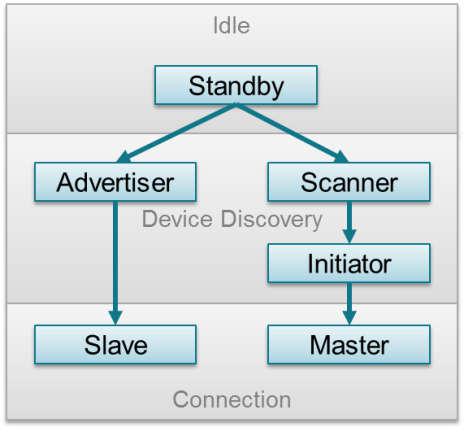
Figure 28. GAP State Diagram.
Based on the role for which the device is configured, GAP State Diagram. shows the states of the device. The following describes these states.
- Standby: The device is in the initial idle state upon reset.
- Advertiser: The device is advertising with specific data letting any initiating devices know that it is a connectible device (this advertisement contains the device address and can contain some additional data such as the device name).
- Scanner: When receiving the advertisement, the scanning device sends a scan request to the advertiser. The advertiser responds with a scan response. This process is called device discovery. The scanning device is aware of the advertising device and can initiate a connection with it.
- Initiator: When initiating, the initiator must specify a peer device address to which to connect. If an advertisement is received matching that address of the peer device, the initiating device then sends out a request to establish a connection (link) with the advertising device with the connection parameters described in Connection Parameters.
- Slave/Master: When a connection is formed, the device functions as a slave if the advertiser and a master if the initiator.
Connection Parameters
This section describes the connection parameters which are sent by the initiating device with the connection request and can be modified by either device when the connection is established. These parameters are as follows:
- Connection Interval - In Bluetooth low energy connections, a
frequency-hopping scheme is used. The two devices each send and
receive data from one another only on a specific channel at a
specific time. These devices meet a specific amount of time later
at a new channel (the link layer of the Bluetooth low energy
protocol stack handles the channel switching). This meeting is
where the two devices send and receive data is known as a
connection event. If there is no application data to be sent or received, the two devices exchange link layer data to maintain the connection. The connection interval is the amount of time between two connection events in units of 1.25 ms. The connection interval can range from a minimum value of 6 (7.5 ms) to a maximum of 3200 (4.0 s). See Connection Event and Interval for more details.
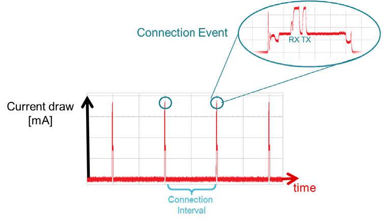
Figure 29. Connection Event and Interval
Different applications may require different connection intervals. As described in Connection Parameter Considerations, these requirements affect the power consumption of the device. For more detailed information on power consumption, see Measuring Bluetooth Smart Power Consumption Application Report (SWRA478).
- Slave Latency - This parameter gives the slave (peripheral) device the option of skipping a number of connection events. This ability gives the peripheral device some flexibility. If the peripheral does not have any data to send, it can skip connection events, stay asleep, and save power. The peripheral device selects whether to wake or not on a per connection event basis. The peripheral can skip connection events but must not skip more than allowed by the slave latency parameter or the connection fails. See Slave Latency for more details.
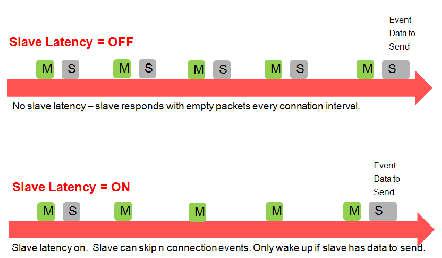
Figure 30. Slave Latency
- Supervision Time-out - This time-out is the maximum amount of time between two successful connection events. If this time passes without a successful connection event, the device terminates the connection and returns to an unconnected state. This parameter value is represented in units of 10 ms. The supervision time-out value can range from a minimum of 10 (100 ms) to 3200 (32.0 s). The time-out must be larger than the effective connection interval (see Effective Connection Interval for more details).
Effective Connection Interval
The effective connection interval is equal to the amount of time between two connection events, assuming that the slave skips the maximum number of possible events if slave latency is allowed (the effective connection interval is equal to the actual connection interval if slave latency is set to 0).
The slave latency value represents the maximum number of events that can be skipped. This number can range from a minimum value of 0 (meaning that no connection events can be skipped) to a maximum of 499. The maximum value must not make the effective connection interval (see the following formula) greater than 16 s. The interval can be calculated using the following formula:
Effective Connection Interval = (Connection Interval) * (1 + [Slave
Latency])
Consider the following example:
- Connection Interval: 80 (100 ms)
- Slave Latency: 4
- Effective Connection Interval: (100 ms) * (1 + 4) = 500 ms
When no data is being sent from the slave to the master, the slave transmits during a connection event once every 500 ms.
Connection Parameter Considerations
In many applications, the slave skips the maximum number of connection events. Consider the effective connection interval when selecting or requesting connection parameters. Selecting the correct group of connection parameters plays an important role in power optimization of the Bluetooth low energy device. The following list gives a general summary of the trade-offs in connection parameter settings.
Reducing the connection interval does as follows:
- Increases the power consumption for both devices
- Increases the throughput in both directions
- Reduces the time for sending data in either direction
Increasing the connection interval does as follows:
- Reduces the power consumption for both devices
- Reduces the throughput in both directions
- Increases the time for sending data in either direction
Reducing the slave latency (or setting it to zero) does as follows:
- Increases the power consumption for the peripheral device
- Reduces the time for the peripheral device to receive the data sent from a central device
Increasing the slave latency does as follows:
- Reduces power consumption for the peripheral during periods when the peripheral has no data to send to the central device
- Increases the time for the peripheral device to receive the data sent from the central device
Connection Parameter Limitations with Multiple Connections
There are additional constraints that exist when connected to multiple devices or performing multiple GAP roles simultaneously. See the multi_role example in BLE-Stack.
Connection Parameter Update
In some cases, the central device requests a connection with a
peripheral device containing connection parameters that are
unfavorable to the peripheral device. In other cases, a peripheral
device might have the desire to change parameters in the middle of a
connection, based on the peripheral application. The peripheral
device can request the central device to change the connection
settings by sending a Connection Parameter Update Request. For
Bluetooth 4.1 and 4.2-capable devices, this request is handled directly by
the Link Layer. For Bluetooth 4.0 devices, the L2CAP layer of the
protocol stack handles the request. The Bluetooth low energy stack
automatically selects the update method.
This request contains four parameters: minimum connection interval, maximum connection interval, slave latency, and time-out. These values represent the parameters that the peripheral device needs for the connection (the connection interval is given as a range). When the central device receives this request, it can accept or reject the new parameters.
Sending a Connection Parameter Update Request is optional and is not
required for the central device to accept or apply the requested
parameters. Some applications try to establish a connection at a
faster connection interval to allow for a faster service discovery
and initial setup. These applications later request a longer
(slower) connection interval to allow for optimal power usage.
Depending on the GAPRole, connection parameter updates can be sent
asynchronously with the GAPRole_SendUpdateParam or
GAPCentralRole_UpdateLink command. The peripheral GAPRole can be
configured to automatically send a parameter update a certain amount of time
after establishing a connection. For example, the simple_peripheral
application uses the following preprocessor-defined symbols:
Six seconds after a connection is established, the GAP layer
automatically sends a connection parameter update. This action
can be disabled by changing DEFAULT_ENABLE_UPDATE_REQUEST to e.g.
GAPROLE_LINK_PARAM_UPDATE_WAIT_REMOTE_PARAMS. See Peripheral Role
for an explanation of how the parameters are configured.
Connection Termination
Either the master or the slave can terminate a connection for any reason. One side initiates termination and the other side must respond before both devices exit the connected state.
GAP Abstraction
The application and profiles can directly call GAP API functions to perform Bluetooth low energy-related functions such as advertising or connecting. Most of the GAP functionality is handled by the GAPRole Task. GAP Abstraction shows this abstraction hierarchy.
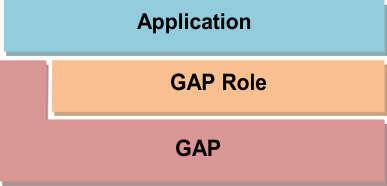
Figure 31. GAP Abstraction
Access the GAP layer through direct calls or through the GAPRole task as described in GAPRole Task. Use the GAPRole task rather than direct calls when possible. Configuring the GAP Layer describes the functions and parameters that are not handled or configured through the GAPRole task and must be modified directly through the GAP layer.
Configuring the GAP Layer
The GAP layer functionality is mostly defined in library code. The
function headers can be found in gap.h in the protocol stack
project. Most of these functions are used by the GAPRole and do not
need to be called directly. For reference, see GATTServApp.
Several parameters exist which may be desirable to modify before starting the
GAPRole. These parameters can be set or get through the
GAP_SetParamValue and GAP_GetParamValue functions and
include advertising and scanning intervals, windows, and so forth (see the API
for more information). The following is the configuration of the GAP layer in
simple_peripheral_init():
1 2 3 4 5 6 7 8 9 | // Set advertising interval
{
uint16_t advInt = DEFAULT_ADVERTISING_INTERVAL;
GAP_SetParamValue(TGAP_LIM_DISC_ADV_INT_MIN, advInt);
GAP_SetParamValue(TGAP_LIM_DISC_ADV_INT_MAX, advInt);
GAP_SetParamValue(TGAP_GEN_DISC_ADV_INT_MIN, advInt);
GAP_SetParamValue(TGAP_GEN_DISC_ADV_INT_MAX, advInt);
}
|
The above code sets the advertising interval for limited and general
advertising modes. By default, the peripheral advertises in general
discoverable mode. To use limited discoverable mode, the
corresponding fields inside the advertising data packet should be
changed by defining DEFAULT_DISCOVERABLE_MODE to
GAP_ADTYPE_FLAGS_LIMITED.
GAPRole Task
The GAPRole task is a separate task which offloads handling most of the GAP layer functionality from the application. This task is enabled and configured by the application during initialization. Based on this configuration, many Bluetooth low energy protocol stack events are handled directly by the GAPRole task and never passed to the application. Callbacks exist that the application can register with the GAPRole task so that the application task can be notified of certain events and proceed accordingly.
Based on the configuration of the device, the GAP layer always operates in one of four roles:
- Broadcaster - The device is an advertiser that is non connectable.
- Observer - The device scans for advertisements but cannot initiate connections.
- Peripheral - The device is an advertiser that is connectable and operates as slave in a single link-layer connection.
The Bluetooth low energy specification allows for certain combinations of multiple-roles, which are supported by the Bluetooth low energy protocol stack. For configuration of the Bluetooth low energy stack features, see Creating a Custom Bluetooth low energy Application
For supported GAPRole API, see BLE-Stack API Reference.
Peripheral Role
The peripheral GAPRole task is defined in peripheral.c and peripheral.h. Peripheral describes the full API including commands, configurable parameters, events, and callbacks. The steps to use this module are as follows:
- Initialize the GAPRole parameters. This
initialization should occur in the application initialization
function. (for example
simple_peripheral_initshown in Listing 42.).
1 2 3 4 5 6 7 8 9 10 11 12 13 14 15 16 17 18 19 20 21 22 23 24 25 26 27 28 29 30 31 32 33 | // Setup the GAP Peripheral Role Profile
{
uint8_t initialAdvertEnable = TRUE;
uint16_t advertOffTime = 0;
uint8_t enableUpdateRequest = DEFAULT_ENABLE_UPDATE_REQUEST;
uint16_t desiredMinInterval = DEFAULT_DESIRED_MIN_CONN_INTERVAL;
uint16_t desiredMaxInterval = DEFAULT_DESIRED_MAX_CONN_INTERVAL;
uint16_t desiredSlaveLatency = DEFAULT_DESIRED_SLAVE_LATENCY;
uint16_t desiredConnTimeout = DEFAULT_DESIRED_CONN_TIMEOUT;
// Set the GAP Role Parameters
GAPRole_setParameter(GAPROLE_ADVERT_ENABLED, sizeof(uint8_t),
&initialAdvertEnable);
GAPRole_setParameter(GAPROLE_ADVERT_OFF_TIME, sizeof(uint16_t),
&advertOffTime); GAPRole_setParameter(GAPROLE_SCAN_RSP_DATA,
sizeof(scanRspData), scanRspData);
GAPRole_setParameter(GAPROLE_ADVERT_DATA, sizeof(advertData),
advertData); GAPRole_setParameter(GAPROLE_PARAM_UPDATE_ENABLE,
sizeof(uint8_t), &enableUpdateRequest);
GAPRole_setParameter(GAPROLE_MIN_CONN_INTERVAL,
sizeof(uint16_t), &desiredMinInterval);
GAPRole_setParameter(GAPROLE_MAX_CONN_INTERVAL,
sizeof(uint16_t), &desiredMaxInterval);
GAPRole_setParameter(GAPROLE_SLAVE_LATENCY, sizeof(uint16_t),
&desiredSlaveLatency);
GAPRole_setParameter(GAPROLE_TIMEOUT_MULTIPLIER,
sizeof(uint16_t), &desiredConnTimeout);
}
|
- Initialize the GAPRole task and pass application callback functions to GAPRole. This should also occur in the application initialization function.
1 2 | // Start the Device
VOID GAPRole_StartDevice(&SimpleBLEPeripheral_gapRoleCBs);
|
- Send GAPRole commands from the application. Figure 32. is an example of the application using GAPRole_TerminateConnection.
1 | GAPRole_TerminateConnection();
|
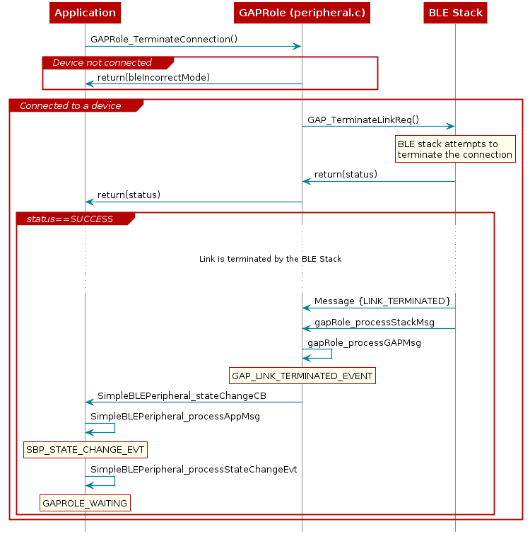
Figure 32. Context Diagram of Application using GAPRole_TerminateConnection().
Note
The return value only indicates whether the attempt to terminate the connection initiated successfully. The actual termination of connection event is returned asynchronously and is passed to the application through a callback.
- The GAPRole task processes most of the GAP-related events passed to it from the Bluetooth low energy protocol stack. The GAPRole task also forwards some events to the application. When a link is terminated, the GAPRole automatically restarts advertising. The following code snippet can be found in peripheral.c
1 2 3 4 5 6 7 8 9 10 11 12 13 14 15 16 17 18 19 20 21 22 23 24 25 26 27 28 29 | case GAP_LINK_TERMINATED_EVENT:
{
//.......
//.......
//.......
// If device was advertising when connection dropped
if (gapRole_AdvNonConnEnabled)
{
// Continue advertising.
gapRole_state = GAPROLE_ADVERTISING_NONCONN;
}
// Else go to WAITING state.
else
{
if(pPkt->reason == LL_SUPERVISION_TIMEOUT_TERM)
{
gapRole_state = GAPROLE_WAITING_AFTER_TIMEOUT;
}
else
{
gapRole_state = GAPROLE_WAITING;
}
// Start advertising, if enabled.
gapRole_setEvent(START_ADVERTISING_EVT);
}
}
break;
|
Generic Attribute Profile (GATT)
Just as the GAP layer handles most connection-related functionality, the GATT layer of the Bluetooth low energy protocol stack is used by the application for data communication between two connected devices. Data is passed and stored in the form of characteristics which are stored in memory on the Bluetooth low energy device. From a GATT standpoint, when two devices are connected they are each in one of two roles.
- The GATT server
- the device containing the characteristic database that is being read or written by a GATT client.
- The GATT client
- the device that is reading or writing data from or to the GATT server.
Figure 33. shows this relationship in a sample Bluetooth low energy connection where the peripheral device (that is, a CC1350 Launchpad) is the GATT server and the central device (that is, a smart phone) is the GATT client.
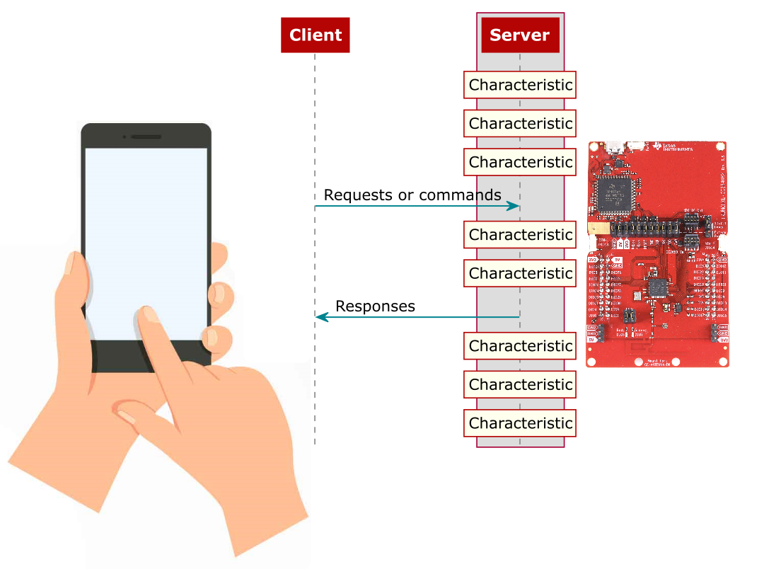
Figure 33. GATT Client and Server Interaction Overview
The GATT roles of client and server are independent from the GAP roles of peripheral and central. A peripheral can be either a GATT client or a GATT server, and a central can be either a GATT client or a GATT server. A peripheral can act as both a GATT client and a GATT server. For a hands-on review of GATT services and characteristics, see SimpleLink Academy.
GATT Characteristics and Attributes
While characteristics and attributes are sometimes used interchangeably when referring to Bluetooth low energy, consider characteristics as groups of information called attributes. Attributes are the information actually transferred between devices. Characteristics organize and use attributes as data values, properties, and configuration information. A typical characteristic is composed of the following attributes.
- Characteristic Value
- data value of the characteristic
- Characteristic Declaration
- descriptor storing the properties, location, and type of the characteristic value
- Client Characteristic Configuration
- a configuration that allows the GATT server to configure the characteristic to be notified (send message asynchronously) or indicated (send message asynchronously with acknowledgment)
- Characteristic User Description
- an ASCII string describing the characteristic
These attributes are stored in the GATT server in an attribute table. In addition to the value, the following properties are associated with each attribute.
- Handle
- the index of the attribute in the table (Every attribute has a unique handle.)
- Type
- indicates what the attribute data represents (referred to as a UUID [universal unique identifier]. Some of these are Bluetooth SIG-defined and some are custom.)
- Permissions
- enforces if and how a GATT client device can access the value of an attribute
GATT Client Abstraction
Like the GAP layer, the GATT layer is also abstracted. This abstraction depends on whether the device is acting as a GATT client or a GATT server. As defined by the Bluetooth Specification, the GATT layer is an abstraction of the ATT layer.
GATT clients do not have attribute tables or profiles as they are gathering, not serving, information. Most of the interfacing with the GATT layer occurs directly from the application.

Figure 34. Visualization of GATT Client Abstraction.
GATT Server Abstraction
As a GATT server, most of the GATT functionality is handled by the individual GATT profiles. These profiles use the GATTServApp (a configurable module that stores and manages the attribute table). Figure 35. shows this abstraction hierarchy.
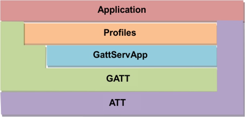
Figure 35. Visualization of GATT Server abstraction.
The design process involves creating GATT profiles that configure the GATTServApp module and use its API to interface with the GATT layer. In this case of a GATT server, direct calls to GATT layer functions are unnecessary. The application then interfaces with the profiles.
GATT Services and Profile
A GATT service is a collection of characteristics. For example, the heart rate service contains a heart rate measurement characteristic and a body location characteristic, among others. Multiple services can be grouped together to form a profile. Many profiles only implement one service so the two terms are sometimes used interchangeably.
Note
TI intends this section as an introduction to the attribute table by using simple_peripheral as an example. For information on how this profile is implemented within the stack, see GATT Server Abstraction.
There are four GATT profiles defined in the simple_peripheral example application project.
- GAP GATT Service (GGS)
This service contains device and access information such as the device name, vendor identification, and product identification.
The following characteristics are defined for this service:
- Device name
- Appearance
- Peripheral preferred connection parameters
Note
See Bluetooth Core_v4.2 specification (vol. 3 Part C, Ch. 12) for more information on these characteristics.
Generic Attribute Service
This service contains information about the GATT server, is a part of the Bluetooth low energy protocol stack, and is required for every GATT server device as per the Bluetooth low energy specification.
Device Info Service
This service exposes information about the device such as the hardware, software version, firmware version, regulatory information, compliance information, and manufacturer name. The Device Info Service is part of the Bluetooth low energy protocol stack and configured by the application.
simple_gatt_profile Service
This service is a sample profile for testing and for demonstration. The full source code is provided in the simple_gatt_profile.c and simple_gatt_profile.h files.
Figure 36. shows the attribute table in the simple_peripheral project.
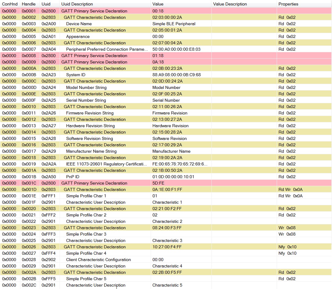
Figure 36. Simple GATT Profile Characteristic Table taken with BTool. Red indicates a Profile declaration, Yellow indicates character declaration, and White indicates Attributes related to a particular characteristic declaration.
The simple_gatt_profile contains the following characteristics:
- SIMPLEPROFILE_CHAR1
- 1-byte value that can be read or written from a GATT client device
- SIMPLEPROFILE_CHAR2
- 1-byte value that can be read from a GATT client device but cannot be written
- SIMPLEPROFILE_CHAR3
- 1-byte value that can be written from a GATT client device but cannot be read
- SIMPLEPROFILE_CHAR4
- 1-byte value that cannot be directly read or written from a GATT client device (This value is notifiable: This value can be configured for notifications to be sent to a GATT client device.)
- SIMPLEPROFILE_CHAR5
- 5-byte value that can be read (but not written) from a GATT client device
The following is a line-by-line description of the simple profile attribute table, referenced by the following handle.
- 0x001C is the simple_gatt_profile service declaration.
This declaration has a UUID of 0x2800 (Bluetooth-defined
GATT_PRIMARY_SERVICE_UUID). The value of this declaration is the UUID of the simple_gatt_profile (custom-defined).
- 0x001D is the SimpleProfileChar1 characteristic declaration.
This declaration can be thought of as a pointer to the SimpleProfileChar1 value. The declaration has a UUID of 0x2803 (Bluetooth-defined
GATT_CHARACTER_UUID). The value of the declaration characteristic, as well as all other characteristic declarations, is a 5-byte value explained here (from MSB to LSB):- Byte 0 is the properties of the SimpleProfileChar1 as defined in the
Bluetooth specification (The following are some of the relevant
properties.)
- 0x02: permits reads of the characteristic value
- 0x04: permits writes of the characteristic value (without a response)
- 0x08: permits writes of the characteristic value (with a response)
- 0x10: permits of notifications of the characteristic value (without acknowledgment)
- 0x20: permits notifications of the characteristic value (with acknowledgment)
The value of 0x0A means the characteristic is readable (0x02) and writeable (0x08).
- Bytes 1-2: the byte-reversed handle where the SimpleProfileChar1’s value is (handle 0x001E)
- Bytes 3-4: the UUID of the SimpleProfileChar1 value (custom-defined 0xFFF1)
- Byte 0 is the properties of the SimpleProfileChar1 as defined in the
Bluetooth specification (The following are some of the relevant
properties.)
- 0x001E is the SimpleProfileChar1 Characteristic Value
This value has a UUID of 0xFFF1 (custom-defined). This value is the actual payload data of the characteristic. As indicated by its characteristic declaration (handle 0x01D), this value is readable and writable.
- 0x001F is the SimpleProfileChar1 Characteristic User Description
This description has a UUID of 0x2901 (Bluetooth-defined). The value of this description is a user-readable string describing the characteristic.
- 0x0020 - 0x002C
are attributes that follow the same structure as the simpleProfileChar1 described previously with regard to the remaining four characteristics. The only different attribute, handle 0x0028, is described as follows.
0x0028 is the SimpleProfileChar4 Client Characteristic Configuration. This configuration has a UUID of 0x2902 (Bluetooth-defined). By writing to this attribute, a GATT server can configure the SimpleProfileChar4 for notifications (writing 0x0001) or indications (writing 0x0002). Writing 0x0000 to this attribute disable notifications and indications.
GATT Security
As described in GATT Server Abstraction, the GATT server may define permissions independently for each characteristic. The server may allow some characteristics to be accessed by any client, while limiting access to other characteristics to only authenticated or authorized clients. These permissions are usually defined as part of a higher level profile specification. For custom profiles, the user may select the permissions as they see fit. For more information about the GATT Security, refer to the Bluetooth Core_v4.2 specification (Vol 3, Part G, section 8).
Authentication
Characteristics that require authentication cannot be accessed until the client has gone through an authenticated pairing method. This verification is performed within the stack, with no processing required by the application. The only requirement is for the characteristic to be registered properly with the GATT server.
For example, characteristic 5 of the simple_gatt_profile allows on authenticated reads.
// Characteristic Value 5
{
{ ATT_BT_UUID_SIZE, simpleProfilechar5UUID },
GATT_PERMIT_AUTHEN_READ,
0,
simpleProfileChar5
},
When an un-authenticated client attempts to read this value, the GATT
server automatically rejects it with ERROR_INSUFFICIENT_AUTHEN (0x41),
without invoking the simpleProfile_ReadAttrCB(). See an example of this
in Sniffer Capture Example.
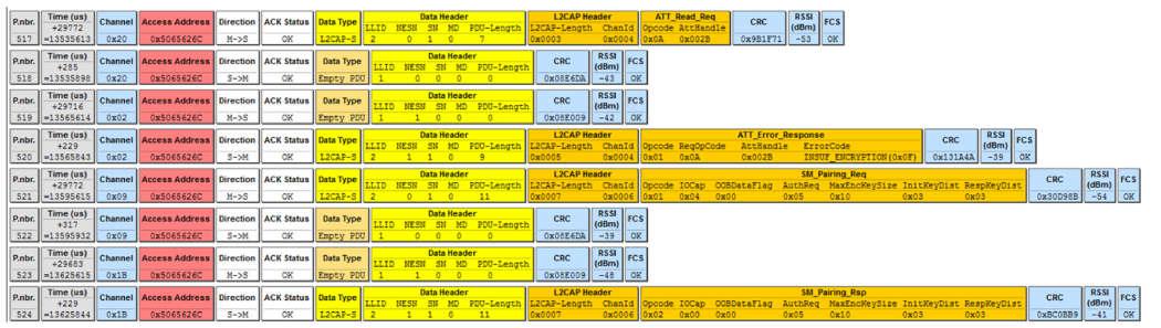
Figure 37. Sniffer Capture Example
After the client has successfully authenticated, read/write requests are forwarded to the profiles read/write callback. See the code below for a simple_gatt_profile example:
case SIMPLEPROFILE_CHAR5_UUID:
*pLen = SIMPLEPROFILE_CHAR5_LEN;
VOID memcpy( pValue, pAttr->pValue, SIMPLEPROFILE_CHAR5_LEN );
break;
Authorization
Authorization is a layer of security provided in addition to what BLE already implements. Because applications are required to define their own requirements for authorization, the stack forwards read/write requests on these characteristics to the application layer of the profile.
For the profile to register for authorization information from the GATT server, it must define an authorization callback with the stack. The simple_gatt_profile does not do this by default, but below is an example of how it could be modified to do this.
- Register profile level authorization callback.
CONST gattServiceCBs_t simpleProfileCBs =
{
simpleProfile_ReadAttrCB, // Read callback function pointer
simpleProfile_WriteAttrCB, // Write callback function pointer
simpleProfile_authorizationCB // Authorization callback function pointer
};
- Implement authorization callback code.
static bStatus_t simpleProfile_authorizationCB( uint16 connHandle, gattAttribute_t *pAttr, uint8 opcode )
{
//This is just an example implementation, normal use cases would require
//more complex logic to determine that the device is authorized
if(clientIsAuthorized)
return SUCCESS;
else
return ATT_ERR_INSUFFICIENT_AUTHOR;
}
The authorization callback executes in the stack context, thus
intensive processing should not be performed in this function. The
implementation is left up to the developer; the above callback
should be treated as a shell. The return value should be either
SUCCESS if the client is authorized to access the characteristic, or
ATT_ERR_INSUFFICIENT_AUTHOR if they have not yet obtained proper
authorization. Authorization requires the connection to be authenticated
beforehand, or ATT_ERR_INSUFFICIENT_AUTHEN will be sent as an error
response.
If a characteristic that requires authorization is registered with
the GATT server, but no application level authorization callback is
defined, the stack will return ATT_ERR_UNLIKELY. Because this
error can be cryptic, TI recommends using an authorization callback.
Using the GATT Layer Directly
This section describes how to use the GATT layer in an application. The functionality of the GATT layer is implemented in the library but header functions can be found in the gatt.h file. ATT_GATT has the complete API for the GATT layer. The Bluetooth Core_v4.2 specification provides more information on the functionality of these commands. These functions are used primarily for GATT client applications. A few server-specific functions are described in the API. Most of the GATT functions returns ATT events to the application, review ATT_GATT for details.
The general procedure to use the GATT layer when functioning as a GATT client (in the simple_central project) is as follows:
![@startuml
participant "Application \n(simple_central.c)" as App
participant ICALL
participant "BLE Stack"
App->ICALL: VOID GATT_InitClient(); \nInitialize Client
App->ICALL: GATT_RegisterForInd(selfEntity); \nRegister to receive incoming \nATT Indications or Notification
App->ICALL: GATT_WriteCharValue(connHandle,\n&req, selfEntity);
activate ICALL
rnote over "ICALL"
Translate into ATT function
and send it to the BLE stack
end note
ICALL->"BLE Stack" : ATT_WriteReq
Deactivate "ICALL"
group Invalid Write Req
"BLE Stack"-> ICALL : return(INVALIDPARAMETER)
ICALL-> App : return(INVALIDPARAMETER)
end
group Valid Write Req
"BLE Stack"-->]: Send ATT_WRITE_REQ
"BLE Stack"-->ICALL : return(SUCCESS)
ICALL-->App : return(SUCCESS)
...
... Wait for the server to respond ...
...
"BLE Stack"<--]: Receive ATT_WRITE_RSP\nor ATT_ERROR_RSP
"BLE Stack"->ICALL: Parse the msg
activate ICALL
rnote over "ICALL"
Send GATT_MSG_EVENT
to the application layer
end note
ICALL->App : Notify application
deactivate "ICALL"
App->App: SimpleBLECentral_processStackMsg
rnote over "App"
GATT_MSG_EVENT
end note
App->App: SimpleBLECentral_processGATTMsg
rnote over "App"
ATT_WRITE_RSP
ATT_ERROR_RSP
end note
end
@enduml](../_images/plantuml-89d327cc173abdd9a29d231b4f1ff89b6bbecdbe.png)
Figure 38. Context Diagram of Application using GATT layer.
Note
Even though the event sent to the application is an ATT
event, it is sent as a GATT protocol stack message
(GATT_MSG_EVENT).
Note
In addition to receiving responses to its own commands, a GATT client may
also receive asynchronous data from the GATT server as indications or
notifications. Use (GATT_RegisterForInd(selfEntity)) to receive these
ATT notifications and indications. These notifications and indications are
also sent as ATT events (ATT_HANDLE_VALUE_NOTI &
ATT_HANDLE_VALUE_IND) in GATT messages to the application. These events
must be handled as described in GATT Services and Profile.
GAP GATT Service (GGS)
The GAP GATT Service (GGS) is required for low-energy devices that implement the central or peripheral role. Multirole devices that implement either of these roles must also contain the GGS. The purpose of the GGS is to aide in the device discovery and connection initiation process.
Note
For more information about the GGS, refer to the Bluetooth Core_v4.2 specification (Vol 3, Part C, section 12).
Using the GGS
This section describes what the application must do to configure, start, and use the GAP Gatt Service. The GGS is implemented as part of the Bluetooth Low Energy library code, the API can be found in GATTServApp. ATT_GATT describes the full API, including commands, configurable parameters, events, and callbacks.
- Include header
#include "gapgattserver.h"
- Initialize GGS parameters.
1 2 3 4 | // GAP GATT Attributes
static uint8_t attDeviceName[GAP_DEVICE_NAME_LEN] = "Simple BLE Peripheral";
GGS_SetParameter(GGS_DEVICE_NAME_ATT, GAP_DEVICE_NAME_LEN, attDeviceName);
|
- Initialize application callbacks with GGS (optional). This notifies the application when any of the characteristics in the GGS have changed.
GGS_RegisterAppCBs(&appGGSCBs);
- Add the GGS to the GATT server.
bStatus_t GGS_AddService(GATT_ALL_SERVICES);
Generic Attribute Profile Service (GATT Service)
The Generic Attribute Profile (GATT) Service provides information about the GATT services registered with a device.
Note
For more information on GATT, refer to Bluetooth Core_v4.2 specification (Vol 3, Part G, section 7).
The service changed characteristic is used to inform bonded devices that services have changed on the server upon reconnection. Service changed updates are sent in the form of GATT indications, and the service changed characteristic is not writeable or readable. In the TI Bluetooth low energy stack, the service changed characteristic is implemented as part of the gattservapp, which is part of library code.
Per the TI Bluetooth low energy stack spec, it is safe for server devices whose characteristic tables do not change over their lifetime to exclude the service changed characteristic. Support for indications from this characteristic must be supported on GATT client devices.
Using the GATT Service
This section describes what the user must do to enable the GATT service changed feature in the Bluetooth low energy stack. Once the service changed feature is enabled, the GAPBondMgr will handle sending the service changed indication to clients who have enabled it using the CCCD.
Use a supported build config for the stack; only stack libraries with v4.1 features and L2CAP connection-oriented channels will support the service changed characteristic.
Enable this feature with the project’s build_config.opt file, by uncommenting the following line:
-DBLE_V41_FEATURES=L2CAP_COC_CFG+V41_CTRL_CFG
From this point, the GAPBondMgr handles sending an indication to connected clients when the service has changed and the CCCD is enabled. If the feature is enabled, the peripheral role invokes the necessary APIs to send the indication through the GAPBondMgr.
On the client side, service changed indications can be registered using the same method as registering for other indications.
GATTServApp Module
The GATT Server Application (GATTServApp) stores and manages the application-wide attribute table. Various profiles use this module to add their characteristics to the attribute table. The Bluetooth low energy stack uses this module to respond to discovery requests from a GATT client. For example, a GATT client may send a Discover all Primary Characteristics message. The Bluetooth low energy stack on the GATT server side receives this message and uses the GATTServApp to find and send over-the-air all of the primary characteristics stored in the attribute table. This type of functionality is beyond the scope of this document and is implemented in the library code. The GATTServApp functions accessible from the profiles are defined in ‘’gattservapp_util.c’’ and the API described in GATTServApp. These functions include finding specific attributes and reading or modifying client characteristic configurations. See Figure 39. for an example of how GATTServApp functions in an application.
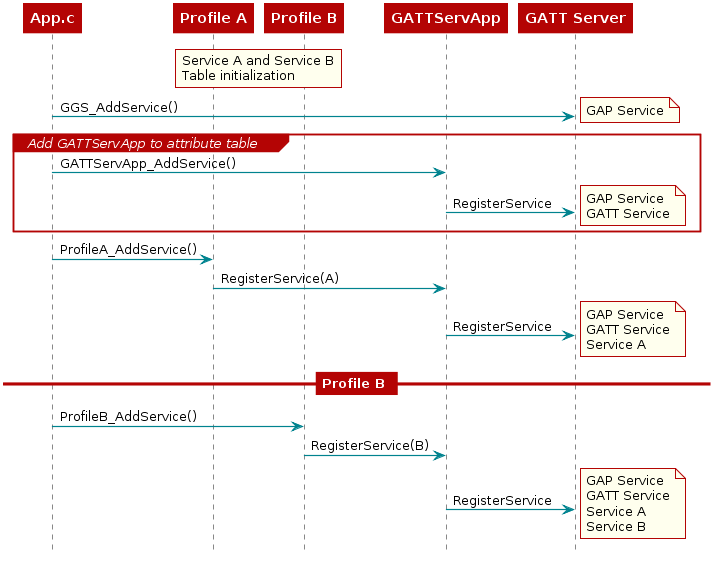
Figure 39. Attribute Table Initialization Diagram.
Building up the Attribute Table
Upon power-on or reset, the application builds the GATT table by using the GATTServApp to add services. Each service consists of a list of attributes with UUIDs, values, permissions, and read and write call-backs. As Figure 39. shows, all of this information is passed through the GATTServApp to GATT and stored in the stack.
Attribute table initialization must occur in the application initialization function, that is, simple_peripheral_init().
// Initialize GATT attributes
GGS_AddService(GATT_ALL_SERVICES); // GAP
GATTServApp_AddService(GATT_ALL_SERVICES); // GATT attributes
Implementing Profiles in Attributes Table
This section describes the general architecture for implementing profiles and provides specific functional examples in relation to the simple_gatt_profile in the simple_peripheral project. See GATT Services and Profile for an overview of the simple_gatt_profile.
Attribute Table Definition
Each service or group of GATT attributes must define a fixed size attribute table that gets passed into GATT. This table in simple_gatt_profile.c is defined as the following.
static gattAttribute_t simpleProfileAttrTbl[SERVAPP_NUM_ATTR_SUPPORTED]
Each attribute in this table is of the following type.
typedef struct attAttribute_t
{
gattAttrType_t type; //!< Attribute type (2 or 16 octet UUIDs)
uint8 permissions; //!< Attribute permissions
uint16 handle; //!< Attribute handle - assigned internally by attribute server
uint8* const pValue; //!< Attribute value - encoding of the octet array is defined in
//!< the applicable profile. The maximum length of an attribute
//!< value shall be 512 octets.
} gattAttribute_t;
When utilizing gattAttribute_t, the various fields have specific meanings.
- gattAttrType_t type
type is the UUID associated with the attribute being placed into the table. gattAttrType_t itself is defined as:
typedef struct { uint8 len; //!< Length of UUID (2 or 16) const uint8 *uuid; //!<Pointer to UUID } gattAttrType_t;
Where length can be either
ATT_BT_UUID_SIZE(2 bytes), orATT_UUID_SIZE(16 bytes). The *uuid is a pointer to a number either reserved by Bluetooth SIG (defined in gatt_uuid.c) or a custom UUID defined in the profile.
- uint8 permissions
enforces how and if a GATT client device can access the value of the attribute. Possible permissions are defined in gatt.h as follows:
#define GATT_PERMIT_READ 0x01 //!< Attribute is Readable #define GATT_PERMIT_WRITE 0x02 //!< Attribute is Writable #define GATT_PERMIT_AUTHEN_READ 0x04 //!< Read requires Authentication #define GATT_PERMIT_AUTHEN_WRITE 0x08 //!< Write requires Authentication #define GATT_PERMIT_AUTHOR_READ 0x10 //!< Read requires Authorization #define GATT_PERMIT_AUTHOR_WRITE 0x20 //!< Write requires Authorization #define GATT_PERMIT_ENCRYPT_READ 0x40 //!< Read requires Encryption #define GATT_PERMIT_ENCRYPT_WRITE 0x80 //!< Write requires Encryption Allocating Memory for GATT Procedures further describes authentication, authorization, and encryption.
- uint16 handle
handle is a placeholder in the table where GATTServApp assigns a handle. This placeholder is not customizable. Handles are assigned sequentially.
- uint8* const pValue
pValue is a pointer to the attribute value. The size is unable to change after initialization. The maximum size is 512 octets.
Service Declaration
Consider the following simple_gatt_profile service declaration attribute:
// Simple Profile Service
{
{ ATT_BT_UUID_SIZE, primaryServiceUUID }, // type
GATT_PERMIT_READ, // permissions
0, // handle
(uint8 *)&simpleProfileService // pValue
}
The type is set to the Bluetooth SIG-defined primary service UUID
(0x2800). A GATT client is permitted to read this service with the permission
is set to GATT_PERMIT_READ. The pValue is a pointer to the UUID of
the service, custom-defined as 0xFFF0. SimpleProfileService itself is defined to
reference the profile’s UUID.
// Simple Profile Service attribute
static CONST gattAttrType_t simpleProfileService =
{
ATT_BT_UUID_SIZE,
simpleProfileServUUID
};
Characteristic Declaration
Consider the following simple_gatt_profile simpleProfileCharacteristic1 declaration.
// Characteristic 1 Declaration
{
{ ATT_BT_UUID_SIZE, characterUUID },
GATT_PERMIT_READ,
0,
&simpleProfileChar1Props
},
The type is set to the Bluetooth SIG-defined characteristic UUID
(0x2803). This makes simpleProfileCharacteristic1 read only to the GATT client
with the permissions set to GATT_PERMIT_READ.
For functional purposes, the only information required to be passed to the GATTServApp in pValue is a pointer to the properties of the characteristic value. The GATTServApp adds the UUID and the handle of the value. These properties are defined to allow this particular characteristic in this service to be read and written to.
// Simple Profile Characteristic 1 Properties
static uint8 simpleProfileChar1Props = GATT_PROP_READ | GATT_PROP_WRITE;
Note
An important distinction exists between these properties and the GATT permissions of the characteristic value. These properties are visible to the GATT client stating the properties of the characteristic value. The GATT permissions of the characteristic value affect its functionality in the protocol stack. These properties must match that of the GATT permissions of the characteristic value.
Characteristic Value
Consider the simple_gatt_profile simpleProfileCharacteristic1 value.
// Characteristic Value 1
{
{ ATT_BT_UUID_SIZE, simpleProfilechar1UUID },
GATT_PERMIT_READ | GATT_PERMIT_WRITE,
0,
&simpleProfileChar1
},
The type is set to the custom-defined simpleProfilechar1 UUID (0xFFF1). The properties of the characteristic value in the attribute table must match the properties from the characteristic value declaration. The pValue is a pointer to the location of the actual value, statically defined in the profile as follows.
// Characteristic 1 Value
static uint8 simpleProfileChar1 = 0;
Client Characteristic Configuration
Consider the simple_gatt_profile simpleProfileCharacteristic4 configuration.
// Characteristic 4 configuration
{
{ ATT_BT_UUID_SIZE, clientCharCfgUuID },
GATT_PERMIT_READ | GATT_PERMIT_WRITE,
0,
(uint8 *)&simpleProfileChar4Config
},
The type is set to the Bluetooth SIG-defined client characteristic configuration UUID (0x2902) GATT clients must read and write to this attribute so the GATT permissions are set to readable and writable. The pValue is a pointer to the location of the client characteristic configuration array, defined in the profile as follows.
1 | static gattCharCfg_t *simpleProfileChar4Config;
|
Note
Client characteristic configuration is represented as an array because this value must be cached for each connection. The catching of the client characteristic configuration is described in more detail in Add Service Function.
Add Service Function
As described in GATTServApp Module, when an application starts up it requires adding the GATT services it supports. Each profile needs a global AddService function that can be called from the application. Some of these services are defined in the protocol stack, such as GAP GATT Service and GATT Service. User-defined services must expose their own AddService function that the application can call for profile initialization. Using SimpleProfile_AddService() as an example, these functions should do as follows.
Allocate space for the client characteristic configuration (CCC) arrays. As an example, a pointer to one of these arrays was initialized in the profile as described in ref:client_characteristic_configuration.
In the AddService function, the supported connections is declared and memory is allocated for each array. Only one CCC is defined in the imple_gatt_profile but there can be multiple CCCs.
// Allocate Client Characteristic Configuration table
simpleProfileChar4Config = (gattCharCfg_t *)ICall_malloc(sizeof(gattCharCfg_t) * linkDBNumConns );
if ( simpleProfileChar4Config == NULL )
{
return ( bleMemAllocError );
}
- Initialize the CCC arrays. CCC values are persistent between power downs and between bonded device connections. For each CCC in the profile, the GATTServApp_InitCharCfg function must be called. This function tries to initialize the CCCs with information from a previously bonded connection and set the initial values to default values if not found.
1 | GATTServApp_InitCharCfg( INVALID_CONHANDLE, simpleProfileChar4Config );
|
- Register the profile with the GATTServApp. This function passes the attribute table of the profile to the GATTServApp so that the attributes of the profile are added to the application-wide attribute table managed by the protocol stack and handles are assigned for each attribute. This also passes pointers to the callbacks of the profile to the stack to initiate communication between the GATTServApp and the profile.
// Register GATT attribute list and CBs with GATT Server App
status = GATTServApp_RegisterService( simpleProfileAttrTbl,
GATT_NUM_ATTRS( simpleProfileAttrTbl ),
GATT_MAX_ENCRYPT_KEY_SIZE,
&simpleProfileCBs );
Register Application Callback Function
Profiles can relay messages to the application using callbacks. In the simple_peripheral project, the simple_gatt_profile calls an application callback whenever the GATT client writes a characteristic value. For these application callbacks to be used, the profile must define a Register Application Callback function that the application uses to set up callbacks during its initialization. The register application callback function for the simple_gatt_profile is the following:
1 2 3 4 5 6 7 8 9 10 11 12 13 | bStatus_t SimpleProfile_RegisterAppCBs( simpleProfileCBs_t *appCallbacks )
{
if ( appCallbacks )
{
simpleProfile_AppCBs = appCallbacks;
return ( SUCCESS );
}
else
{
return ( bleAlreadyInRequestedMode );
}
}
|
Where the callback typedef is defined as the following.
typedef struct
{
simpleProfileChange_t pfnSimpleProfileChange; // Called when characteristic value changes
} simpleProfileCBs_t;
The application must then define a callback of this type and pass it to the simple_gatt_profile with the SimpleProfile_RegisterAppCBs() function. This occurs in simple_peripheral.c as follows.
//Simple GATT Profile Callbacks
#ifndef FEATURE_OAD_ONCHIP
static simpleProfileCBs_t SimpleBLEPeripheral_simpleProfileCBs =
{
SimpleBLEPeripheral_charValueChangeCB // Characteristic value change callback
};
#endif //!FEATURE_OAD_ONCHIP
//...
//Register callback with SimpleGATTprofile
SimpleProfile_RegisterAppCBs(&SimpleBLEPeripheral_simpleProfileCBs);
See Read and Write Callback Functions for further information on how this callback is used.
Read and Write Callback Functions
The profile must define Read and Write callback functions which the protocol stack calls when one of the attributes of the profile are written to or read from. The callbacks must be registered with GATTServApp as mentioned in Add Service Function. These callbacks perform the characteristic read or write and other processing (possibly calling an application callback) as defined by the specific profile.
Read Request from Client
When a read request from a GATT Client is received for a given attribute, the protocol stack checks the permissions of the attribute and, if the attribute is readable, calls the read call-back profile. The profile copies in the value, performs any profile-specific processing, and notifies the application if desired. This procedure is illustrated in Figure 40. for a read of simpleprofileChar1 in the simple_gatt_profile.
![@startuml
participant "Service CB \n(simple_gatt_profile.c)" as App
participant GATTServApp
participant "BLE Stack" as BLE
BLE <--]: Receive Attribute Read Request
BLE -> GATTServApp : GATT_MSG_EVENT
Activate "GATTServApp"
GATTServApp -> GATTServApp : Process Event
GATTServApp -> GATTServApp : Process Msg "ATT Read Req"
group status != SUCCESS
GATTServApp -> BLE : ATT_ErrorRsp
Deactivate "GATTServApp"
BLE -->] : Send ATT_ERROR_RSP
end
group status == SUCCESS
GATTServApp -> App : Find Attribute CB
App -> App : simpleProfile_ReadAttrCB
rnote over "App"
Copy the values
end note
App -> GATTServApp
GATTServApp -> BLE : ATT_ReadRsp
BLE -->] : ATT_READ_RSP
end
@enduml](../_images/plantuml-566bab86917812dd02525d3c4dcde2efddc32b41.png)
Figure 40. Read Request illustration
The processing is in the context of the protocol stack. If any intensive profile-related processing that must be done in the case of an attribute read, this should be split up and done in the context of the Application task. See the Write Request from Client for more information.
Write Request from Client
When a write request from a GATT client is received for a given attribute, the protocol stack checks the permissions of the attribute and, if the attribute is write-permitted, calls the write callback of the profile. The profile stores the value to be written, performs any profile-specific processing, and notifies the application if desired. Figure 41. shows this procedure for a write of simpleprofileChar3 in the simple_gatt_profile.
![@startuml
participant "User Define Post Processing" as User
participant "Service CB \n(simple_gatt_profile.c)" as App
participant GATTServApp
participant "BLE Stack" as BLE
BLE <--]: Receive Attribute Write Request
BLE -> GATTServApp : GATT_MSG_EVENT
Activate "GATTServApp"
GATTServApp -> GATTServApp : Process Event
GATTServApp -> GATTServApp : Process Msg "ATT Write Req"
group status != SUCCESS
GATTServApp -> BLE : ATT_ErrorRsp
Deactivate "GATTServApp"
BLE -->] : Send ATT_ERROR_RSP
end
group status == SUCCESS
GATTServApp -> App : Find Attribute CB
App -> App : simpleProfile_WriteAttrCB
rnote over "App"
update the value
&
find user defined application callback
end note
GATTServApp -> BLE : ATT_WriteRsp
BLE -->] : ATT_Write_RSP
App -> User : SimpleBLEPeripheral_\ncharValueChangeCB()
User-> User : SimpleBLEPeripheral_\nenqueueMsg()
rnote over "User"
SBP_CHAR_CHANGE_EVT
end note
User-> User : SimpleBLEPeripheral_\nprocessCharValueChangeEvt()
rnote over "User"
Get the new value and
do whatever you want with it
end note
end
@enduml](../_images/plantuml-c3f8c03c982abf0cbcf66a77754f8159697adfe5.png)
Figure 41. Write Request illustration
Important
Minimizing the processing in protocol stack context is important. In this example, additional processing beyond storing the attribute write value in the profile occurs in the application context by enqueuing a message in the queue of the application.
Get and Set Functions
The profile containing the characteristics shall provide set and get abstraction functions for the application to read and write a characteristic of the profile. The set parameter function also includes logic to check for and implement notifications and indications if the relevant characteristic has notify or indicate properties. Figure 42. and the following code show this example for setting simpleProfileChacteristic4 in the simple_gatt_profile.
![@startuml
participant App
participant "Profile \n(simple_gatt_profile.c)" as profile
participant GATTServApp
participant "BLE Stack" as BLE
App -> profile : SetParameter(param, len, value)
group Invalid operation
profile -> App : return(bleInvalidRange|\nINVALIDPARAMETER)
end note
group Valid operation (correct len etc)
rnote over "profile"
Copy and update the values
end note
profile -> GATTServApp : GATTServApp_ProcessCharCfg()
rnote over "GATTServApp"
Check if the notification has
already been enabled
end note
group Notification is not enabled
GATTServApp -> profile : return(SUCCESS)
profile -> App : return(SUCCESS)
end
group Notification is enabled
GATTServApp -> BLE : GATT_Notification()
BLE -->]: Send notification to client
BLE->GATTServApp : return(status)
GATTServApp -> profile : return(status)
profile -> App : return(SUCCESS)
end
end note
@enduml](../_images/plantuml-f3f8a6313905aec0a8ee67778d39af556ae21fc8.png)
Figure 42. Set Profile Parameter
For example, the application initializes simpleProfileCharacteristic4 to 0 in simple_peripheral.c through the following.
uint8_t charValue4 = 0;
SimpleProfile_SetParameter(SIMPLEPROFILE_CHAR4, sizeof(uint8_t), &charValue4);
The code for this function is displayed in the following code snippet (from simple_gatt_profile.c). Besides setting the value of the static simpleProfileChar4, this function also calls GATTServApp_ProcessCharCfg because it has notify properties. This action forces GATTServApp to check if notifications have been enabled by the GATT Client. If so, the GATTServApp sends a notification of this attribute to the GATT Client.
1 2 3 4 5 6 7 8 9 10 11 12 13 14 | bStatus_t SimpleProfile_SetParameter( uint8 param, uint8 len, void *value )
{
bStatus_t ret = SUCCESS switch ( param )
{
case SIMPLEPROFILE_CHAR4:
if ( len == sizeof ( uint8 ) )
{
simpleProfileChar4 = *((uint8*)value);
// See if Notification has been enabled
GATTServApp_ProcessCharCfg( simpleProfileChar4Config, &simpleProfileChar4, FALSE,
simpleProfileAttrTbl, GATT_NUM_ATTRS( simpleProfileAttrTbl ),
INVALID_TASK_ID, simpleProfile_ReadAttrCB );
}
|
Queued Writes
Prepare Write commands allows a GATT server to send more payload data by queuing up multiple write requests. The default queue size is 5. With a default MTU of 23 and payload of 18 bytes, up to 90 bytes of payload can be sent. Refer to Bluetooth Core_v4.2 specification (Vol 3, Part F, Section 3.4.6) for more information on queued writes.
Adjust the Prepare Write queue with GATTServApp_SetParameter with
parameter GATT_PARAM_NUM_PREPARE_WRITES. There is no specified
limit, but it is bounded by the available HEAPMGR space.
Allocating Memory for GATT Procedures
To support fragmentation, GATT and ATT payload structures must be dynamically allocated for commands sent wirelessly. For example, a buffer must be allocated when sending a GATT_Notification. The stack does this allocation if the preferred method to send a GATT notification or indication is used: calling a SetParameter function of the profile (that is, SimpleProfile_SetParameter()) and calling GATTServApp_ProcessCharCfg as described in Get and Set Functions.
If using GATT_Notification or GATT_Indication directly, memory management must be added as follows.
- Try to allocate memory for the notification or indication payload using GATT_bm_alloc.
- Send notification or indication using GATT_Notification or GATT_Indication if the allocation succeeds.
Note
If the return value of the notification or indication is
SUCCESS (0x00), the stack freed the memory.
Use GATT_bm_free to free the memory if the return value is something other than
SUCCESS(for example,blePending).The following is an example of this in the
GATTServApp_SendNotiIndfunction in the gattservapp_util.c file.
1 2 3 4 5 6 7 8 9 10 11 12 13 14 15 16 17 18 19 20 21 22 23 24 25 26 27 28 29 30 31 | noti.pValue = (uint8 *)GATT_bm_alloc( connHandle, ATT_HANDLE_VALUE_NOTI, GATT_MAX_MTU, &len );
if ( noti.pValue != NULL )
{
status = (*pfnReadAttrCB)( connHandle, pAttr, noti.pValue, ¬i.len, 0, len, GATT_LOCAL_READ );
if ( status == SUCCESS )
{
noti.handle = pAttr->handle;
if ( cccValue & GATT_CLIENT_CFG_NOTIFY )
{
status = GATT_Notification( connHandle, ¬i, authenticated );
}
else // GATT_CLIENT_CFG_INDICATE
{
status = GATT_Indication( connHandle, (attHandleValueInd_t *)¬i, authenticated, taskId );
}
}
if ( status != SUCCESS )
{
GATT_bm_free( (gattMsg_t *)¬i, ATT_HANDLE_VALUE_NOTI );
}
}
else
{
status = bleNoResources;
}
|
For other GATT procedures, take similar steps as noted in ATT_GATT.
Registering to Receive Additional GATT Events in the Application
Using GATT_RegisterForMsgs, receiving additional GATT messages to handle certain corner cases is possible. This possibility can be seen in simple_peripheral_processGATTMsg(). The following three cases are currently handled.
- GATT server in the stack was unable to send an ATT response (due to
lack of available HCI buffers): Attempt to transmit on the next
connection interval. Additionally, a status of
bleTimeoutis sent if the ATT transaction is not completed within 30 seconds, as specified in the core spec.
1 2 3 4 5 6 7 8 9 10 11 12 13 14 15 16 17 18 | // See if GATT server was unable to transmit an ATT response
if (pMsg->hdr.status == blePending)
{
//No HCI buffer was available. Let's try to retransmit the response
//on the next connection event.
if (HCI_EXT_ConnEventNoticeCmd(pMsg->connHandle, selfEntity, SBP_CONN_EVT_END_EVT) == SUCCESS)
{
//First free any pending response
SimpleBLEPeripheral_freeAttRsp(FAILURE);
//Hold on to the response message for retransmission
pAttRsp = pMsg;
//Don't free the response message yet
return (FALSE);
}
}
|
An ATT flow control violation: The application is notified that the connected device has violated the ATT flow control specification, such as sending a Read Request before an Indication Confirm is sent.
No more ATT requests or indications can be sent wirelessly during the connection. The application may want to terminate the connection due to this violation. As an example in simple_peripheral, the LCD is updated.
1 2 3 4 5 6 7 8 9 | else if (pMsg->method == ATT_FLOW_CTRL_VIOLATED_EVENT)
{
//ATT request-response or indication-confirmation flow control is
//violated. All subsequent ATT requests or indications will be dropped.
//The app is informed in case it wants to drop the connection.
//Display the opcode of the message that caused the violation.
DISPLAY_WRITE_STRING_VALUE("FC Violated: %d", pMsg->msg.flowCtrlEvt.opcode, LCD_PAGE5);
}
|
- An ATT MTU size is updated: The application is notified in case this affects its processing in any way. See Maximum Transmission Unit (MTU) for more information on the MTU. As an example in simple_peripheral, the LCD is updated.
1 2 3 4 5 | else if (pMsg->method == ATT_MTU_UPDATED_EVENT)
{
// MTU size updated
DISPLAY_WRITE_STRING_VALUE("MTU Size: $d", pMsg->msg.mtuEvt.MTU, LCD_PAGE5);
}
|
GAP Bond Manager and LE Secure Connections
The GAP Bond Manager is a configurable module that offloads most of the security mechanisms from the application. Table 11. lists the terminology.
| Term | Description |
| Authentication | The pairing process including MITM (Man in the Middle) protection. |
| Authorization | An additional application level key exchange in addition to authentication. |
| Bonding | Storing the keys in nonvolatile memory to use for the next encryption sequence. |
| Encryption | Data is encrypted after pairing or re-encryption (a subsequent connection where keys are looked up from nonvolatile memory). |
| Just Works | Pairing method where keys are transferred over the air without MITM protection. |
| MITM | Man in the Middle protection. This prevents an attacker from listening to the keys transferred over the air to break the encryption. |
| OOB | Out of Band. Keys are not exchanged over the air, but rather over some other source such as a serial port or NFC. This also provides MITM protection. |
| Pairing | The process of exchanging keys. |
The general process that the GAPBondMgr uses is as follows:
- The pairing process exchanges keys through the following methods described in Selection of Pairing Mode.
- Encrypt the link with keys from Step 1.
- The bonding process stores keys in secure flash (SNV).
- Use the keys stored in SNV to encrypt the link when reconnecting.
Tip
Performing all of these steps is not necessary. For example, two devices may choose to pair but not bond.
Selection of Pairing Mode
Version 4.2 of the Bluetooth Spec introduces the Secure Connections feature to upgrade BLE pairing. For a detailed description of the algorithms used for Secure Connections, see Bluetooth Core_v4.2 specification (Section 5.1 of Vol 1, Part A). The previous pairing methods used in the 4.1 and 4.0 Bluetooth Specs are still available, and are now defined as LE legacy pairing. The main difference is that Secure Connections uses Elliptic Curve Diffie-Hellman cryptography, while LE legacy pairing does not.
There are four types of pairing models, each of which are described in detail in GAPBondMgr Examples for Different Pairing Modes:
- just works (Secure Connections or LE Legacy)
- passkey entry (Secure Connections or LE Legacy)
- numeric comparison (Secure Connections)
- out of band (Secure Connections or LE Legacy)
The selection of the association model and whether or not pairing will succeed is based upon the following parameters (all tables from Section 2.3.5.1 of Vol 3, Part H of the Bluetooth Core_v4.2 specification). The GAPBondMgr parameters, as they map to the table parameters below are listed here. For more information on these parameters, see GAPBondMgr.
GAPBOND_LOCAL_OOB_SC_ENABLED: OOB Set / Not SetGAPBOND_MITM_PROTECTION: MITM Set / Not SetGAPBOND_IO_CAPABILITIES: IO CapabilitiesGAPBOND_SECURE_CONNECTION: secure connections supported / not supportedBeyond what the spec defines, this parameter also affects whether or not pairing succeeds, as described in GAPBondMgr.
If both devices support secure connections, use Figure 43. to decide upon the next step.
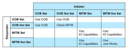
Figure 43. Parameters With Secure Connections.
If at least one device does not support secure connections, use Figure 44. to decide upon the next step.
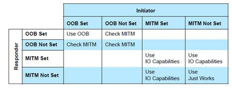
Figure 44. Parameters Without Secure Connections.
If, based on one of the previous tables, IO capabilities are to be used to determine the association model, use Figure 45.
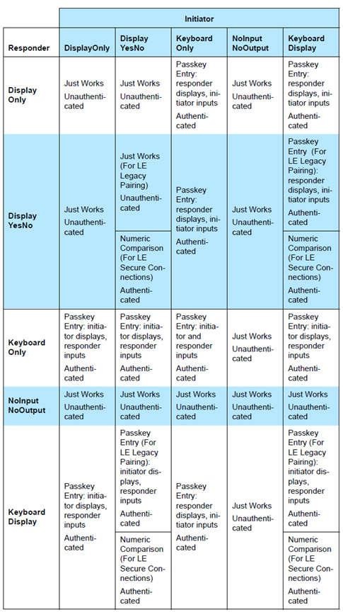
Figure 45. Parameters With IO Capabilities
Using GAPBondMgr
This section describes what the application must do to configure, start, and use the GAPBondMgr. The GAPRole handles some of the GAPBondMgr functionality. The GAPBondMgr is defined in gapbondmgr.c and gapbondmgr.h. GAPBondMgr describes the full API including commands, configurable parameters, events, and callbacks. The project being considered here is the security_examples_central project available from the TI SimpleLink GitHub. The general steps to use the GAPBondMgr module are as follows:
Note
The security examples on Github are not implemented for the CC1350. However, the code steps to use GAPBondMgr and pairing/bonding is the same for CC1350.
- Configure the stack to include GAPBondMgr functionality and, if
desired, secure connections. Define the following in
build_config.optin the stack project:DGAP_BOND_MGRDBLE_V42_FEATURES=SECURE_CONNS_CFG
- The stack must also be configured to use 1 or 2 SNV pages, by
defining
OSAL_SNV=1orOSAL_SNV=2as a preprocessor-defined symbol in the stack project. - If using Secure Connections, the PDU size must be >= 69. This can be
set by defining the following preprocessor symbol in the
application project:
MAX_PDU_SIZE=69. Also, the minimum heap size that can be used with Secure Connections is 3690. - Configure the GAPBondMgr by initializing its parameters as desired. See ATT_GATT for a complete list of parameters with functionality described. There are examples of this for the various pairing / bonding modes in GAPBondMgr Examples for Different Pairing Modes.
- Register application callbacks with the GAPBondMgr, so that the application can communicate with the GAPBondMgr and be notified of events. See an example of this in the ATT_GATT for the callback definitions.
// GAP Bond Manager Callbacks
static gapBondCBs_t application_BondMgrCBs =
{
(pfnPasscodeCB_t)application_passcodeCB, // Passcode callback
application_pairStateCB // Pairing / Bonding state Callback (not used by application)
};
// Register with bond manager after starting device
GAPBondMgr_Register(&application_bondCB);
Note
This should occur in the application initialization function after the GAPRole profile is started (that is, GAPRole_StartDevice).
Define and implement your Passcode and Pairing callback functions. As usual, a callback function should do as little as possible to avois blocking the application. E.g. you can post an event to the application event queue:
/********************************************************************* * @fn application_pairStateCB * * @brief Pairing state callback. * * @return none */ static void application_pairStateCB(uint16_t connHandle, uint8_t state, uint8_t status) { uint8_t *pData; // Allocate space for the event data. if ((pData = ICall_malloc(sizeof(uint8_t)))) { *pData = status; // Queue the event. application_enqueueMsg(APPLICATION_PAIRING_STATE_EVT, state, pData); } }
Once the GAPBondMgr is configured, it operates mostly autonomously from the perspective of the application. When a connection is established, it initiates pairing and bonding, depending on the configuration parameters set during initialization, and communicates with the application as needed through the defined callbacks.
A few parameters can be set and functions called asynchronously at any time from the application. See GAPBondMgr for more information.
Most communication between the GAPBondMgr and the application at this point occurs through the callbacks which were registered in Step 2. Figure 46. is a flow diagram example from simple_central of the GAPBondMgr notifying the application that pairing has been completed. The same method occurs for various other events and will be expanded upon in the following section.
Note
simple_central is not supported on CC1350, but the code flow is the same regardless of example project.
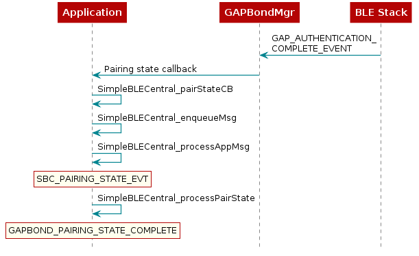
Figure 46. GapBondMgr Callback Example.
GAPBondMgr Examples for Different Pairing Modes
This section provides message diagrams for the types of security that can be implemented. These modes assume acceptable I/O capabilities are available for the security mode, and that the selection of whether or not to support Secure Connections allows for the pairing mode. See the Selection of Pairing Mode on how these parameters affect pairing. These examples only consider the pairing aspect. Bonding can be added to each type of pairing in the same manner and is shown in the next section.
Caution
The code snippets here are not complete functioning examples, and are only intended for illustration purposes.
Pairing Disabled
With pairing set to FALSE, the BLE stack automatically rejects any
attempt at pairing. Configure the GAPBondMgr as follows to disable
pairing:
uint8 pairMode = GAPBOND_PAIRING_MODE_NO_PAIRING;
GAPBondMgr_SetParameter(GAPBOND_PAIRING_MODE, sizeof(uint8_t), &pairMode);
Just Works Pairing
Just Works pairing allows encryption without MITM authentication and is vulnerable to MITM attacks. Just Works pairing can use LE Legacy or Secure Connections pairing. The GAPBondMgr does not need any additional input from the application for just works pairing. Configure the GAPBondMgr for Just Works pairing as follows.
uint8_t pairMode = GAPBOND_PAIRING_MODE_INITIATE;
uint8_t mitm = FALSE;
GAPBondMgr_SetParameter( GAPBOND_PAIRING_MODE, sizeof (uint8_t), &pairMode);
GAPBondMgr_SetParameter( GAPBOND_MITM_PROTECTION, sizeof (uint8_t), &mitm);
Figure 47. describes the interaction between the GAPBondMgr and
the application for Just Works pairing. As shown, the application
receives a GAPBOND_PAIRING_STATE_STARTED event once the pairing
request has been sent, and a GAPBOND_PAIRING_STATE_COMPLETE event
once the pairing process has been completed. At this time, the link is
encrypted.
![@startuml
participant Application
participant GAPRole
participant Gapbondmgr as "GAPBondMgr"
participant BLEStack as "BLE Stack"
BLEStack -> GAPRole : GAP_LINK_ESTABLISHED_EVENT
GAPRole -> Gapbondmgr : GAPBondMgr_LinkEst()
Gapbondmgr -> BLEStack : GAP_Authenticate()
BLEStack -->] : Pairing req
Gapbondmgr -> Application : Pairing state callback
rnote over Application
GAPBOND_PAIRING_
STATE_STARTED
end note
BLEStack -->] : Encryption req
BLEStack <--] : Encryption rsp
BLEStack -> Gapbondmgr : GAP_AUTHENTICATION_\nCOMPLETE_EVENT
Gapbondmgr -> Application : Pairing state callback
rnote over Application
GAPBOND_PAIRING_
STATE_COMPLETE
end note
@enduml](../_images/plantuml-8a2afb442fc5873402d3d0080fe321976ee14120.png)
Figure 47. Just Works Pairing.
Passcode Entry
Passkey entry is a type of authenticated pairing that can prevent MITM attacks. It can use either LE Legacy pairing or Secure Connections pairing. In this pairing method, one device displays a 6-digit passcode, and the other device enters the passcode. As described in Selection of Pairing Mode, the IO capabilities decide which device performs which role. The passcode callback registered with the GAPBondMgr when it was started is used to enter or display the passcode. The following is an example of initiating Passcode Entry pairing where the passcode is displayed.
- Define passcode callback
1 2 3 4 5 6 7 8 9 10 11 12 13 14 15 16 17 18 19 20 21 22 23 | // Bond Manager Callbacks
static gapBondCBs_t application_central_bondCB =
{
(pfnPasscodeCB_t)pplication_central_passcodeCB, //Passcode callback
application_pairStateCB //Pairing state callback
};
static void application_passcodeCB(uint8_t *deviceAddr, uint16_t connHandle, uint8_t uiInputs,
uint8_t uiOutputs, uint32_t numComparison)
{
gapPasskeyNeededEvent_t *pData; // Allocate space for the passcode event.
if ((pData = ICall_malloc(sizeof(gapPasskeyNeededEvent_t))))
{
memcpy(pData->deviceAddr, deviceAddr, B_ADDR_LEN);
pData->connectionHandle = connHandle;
pData->uiInputs = uiInputs;
pData->uiOutputs = uiOutputs;
// Enqueue the event.
application_enqueueMsg(APPLICATION_PASSCODE_NEEDED_EVT, 0, (uint8_t *) pData);
}
}
|
- Configure GAPBondMgr
1 2 3 4 | uint8_t pairMode = GAPBOND_PAIRING_MODE_INITIATE;
uint8_t mitm = TRUE;
GAPBondMgr_SetParameter(GAPBOND_PAIRING_MODE, sizeof(uint8_t), &pairMode);
GAPBondMgr_SetParameter(GAPBOND_PAIRING_MODE, sizeof(uint8_t), &mitm);
|
- Process passcode callback and send response to stack
1 2 3 4 5 6 7 8 9 10 11 12 13 14 15 16 17 18 19 | static void application_processPasscode(uint16_t connectionHandle, gapPasskeyNeededEvent_t *pData)
{
if (pData->uiInputs) // if we are to enter passkey
{
passcode = 111111;
// Send passcode response
GAPBondMgr_PasscodeRsp(connectionHandle, SUCCESS, passcode);
}
else if (pData->uiOutputs) // if we are to display passkey
{
passcode = 111111;
DISPLAY_WRITE_STRING_VALUE("Passcode: %d", passcode, LCD_PAGE4);
// Send passcode response
GAPBondMgr_PasscodeRsp(connectionHandle, SUCCESS, passcode);
}
}
|
Depending on what the uiInputs and uiOutputs returned from the
GAPBondMgr are, the passcode must either be displayed or entered. The
passcode is then sent to the GAPBondMgr using
GAPBondMgr_PasscodeRsp, so that pairing can continue. In this case,
the password is statically set to 111111. In a real product, the password will
likely be randomly generated, and the device must expose a way for the user to
enter the passcode. Then the passcode must be sent to the GAPBondMgr using
GAPBondMgr_PasscodeRsp. The complete interaction between the
GAPBondMgr and the application is shown in Figure 48..
![@startuml
participant Application
participant GAPRole
participant Gapbondmgr as "GAPBondMgr"
participant BLEStack as "BLE Stack"
BLEStack -> GAPRole : GAP_LINK_ESTABLISHED_EVENT
GAPRole -> Gapbondmgr : GAPBondMgr_LinkEst()
Gapbondmgr -> BLEStack : GAP_Authenticate()
BLEStack -->] : Pairing req
Gapbondmgr -> Application : Pairing state callback
rnote over Application
GAPBOND_PAIRING_
STATE_STARTED
end note
BLEStack -> Gapbondmgr : GAP_PASSKEY_NEEDED_\nEVENT
Gapbondmgr -> Application : Passcode callback
[--> Application : Enter or display\npasscode
Application -> Gapbondmgr : GAPBondMgr_PasscodeRsp()
Gapbondmgr -> BLEStack : GAP_PasscodeUpdate()
BLEStack -->] : Encryption req
BLEStack <--] : Encryption rsp
BLEStack -> Gapbondmgr : GAP_AUTHENTICATION_\nCOMPLETE_EVENT
Gapbondmgr -> Application : Pairing state callback
rnote over Application
GAPBOND_PAIRING_
STATE_COMPLETE
end note
@enduml](../_images/plantuml-398c1ac704cb4a7319c4c50da24f27ebe2c26a0b.png)
Figure 48. Interaction Between the GAPBondMgr and the Application when exchanging passcode.
Numeric Comparison
Numeric comparison is a type of authenticated pairing that protects from MITM attacks. It is only possible as Secure Connections pairing; not LE legacy. For numeric comparison pairing, both devices display a 6-digit code. Each device must then indicate, through a button press or some other yes-no input, whether the codes match. The passcode callback registered with the GAPBondMgr when it was started is used to display the 6-digit code. The following is an example of initiating Numeric Comparison pairing where the passcode is displayed. The IO capabilities must be set appropriately to select numeric comparison (that is, Display/Yes-No on both sides). Follow these steps to implement numeric comparison pairing:
- Define passcode callback to display code.
1 2 3 4 5 6 7 8 9 10 11 12 13 14 15 16 17 18 19 20 21 | // Bond Manager Callbacks
static gapBondCBs_t application_bondCB =
{
(pfnPasscodeCB_t)application_passcodeCB, //Passcode callback
application_pairStateCB //Pairing state callback
};
static void application_passcodeCB (uint8_t *deviceAddr, uint16_t connHandle, uint8_t uiInputs,
uint8_t uiOutputs, uint32_t numComparison)
{
gapPasskeyNeededEvent_t *pData;
// Allocate space for the passcode event.
if ((pData = ICall_malloc(sizeof(gapPasskeyNeededEvent_t))))
{
memcpy(pData->deviceAddr, deviceAddr, B_ADDR_LEN);
pData->connectionHandle = connHandle;
pData->numComparison = numComparison;
// Enqueue the event.
application_enqueueMsg(APPLICATION_PASSCODE_NEEDED_EVT, 0, (uint8_t *) pData);
|
- Configure GAPBondMgr.
1 2 3 4 5 6 7 8 9 | uint8_t pairMode = GAPBOND_PAIRING_MODE_INITIATE;
uint8_t scMode = GAPBOND_SECURE_CONNECTION_ONLY;
uint8_t mitm = TRUE;
uint8_t ioCap = GAPBOND_IO_CAP_DISPLAY_YES_NO;
GAPBondMgr_SetParameter(GAPBOND_IO_CAPABILITIES, sizeof(uint8_t), &ioCap);
GAPBondMgr_SetParameter(GAPBOND_PAIRING_MODE, sizeof(uint8_t), &pairMode);
GAPBondMgr_SetParameter(GAPBOND_MITM_PROTECTION, sizeof(uint8_t), &mitm);
GAPBondMgr_SetParameter(GAPBOND_SECURE_CONNECTION, sizeof(uint8_t), &scMode);
|
- Process passcode callback and display code.
1 2 3 4 5 6 7 8 9 10 | static void application_processPasscode (uint16_t connectionHandle, gapPasskeyNeededEvent_t *pData)
{
if (pData->numComparison) //numeric comparison
{
//Display passcode
DISPLAY_WRITE_STRING_VALUE("Num Cmp: %d", pData->numComparison, LCD_PAGE4);
}
}
|
- Accept Yes-No input from user and send response to GAPBondMgr.
1 2 3 4 5 6 | if (keys & KEY_RIGHT)
{
GAPBondMgr_PasscodeRsp(connHandle, SUCCESS, TRUE);
DISPLAY_WRITE_STRING("Codes Match!", LCD_PAGE5);
return;
}
|
In this case, the third parameter of GAPBondMgr_PasscodeRsp, which usually
accepts a passcode, is overloaded to send TRUE to the stack to indicate that the
codes match and to continue with pairing. The process of numeric comparison is
illustrated in Figure 49.
![@startuml
participant Application
participant GAPRole
participant Gapbondmgr as "GAPBondMgr"
participant BLEStack as "BLE Stack"
BLEStack -> GAPRole : GAP_LINK_ESTABLISHED_EVENT
GAPRole -> Gapbondmgr : GAPBondMgr_LinkEst()
Gapbondmgr -> BLEStack : GAP_Authenticate
BLEStack -->] : Pairing req
Gapbondmgr -> Application : Pairing state callback
rnote over Application
GAPBOND_PAIRING_
STATE_STARTED
end note
BLEStack -> Gapbondmgr : GAP_PASSKEY_\nNEEDED_EVENT
Gapbondmgr -> Application : Passcode callback
[<-- Application : Display code
[--> Application : Codes match
Application -> Gapbondmgr : GAPBondMgr_PasscodeRsp()
Gapbondmgr -> BLEStack : GAP_PasscodeUpdate()
BLEStack -->] : Encryption req
BLEStack <--] : Encryption rsp
BLEStack -> Gapbondmgr : GAP_AUTHENTICATION_\nCOMPLETE_EVENT
Gapbondmgr -> Application : Pairing state callback
rnote over Application
GAPBOND_PAIRING_
STATE_COMPLETE
end note
@enduml](../_images/plantuml-d3d3112f75ac73e3219f7a70a0e30ac915078e31.png)
Figure 49. Numeric Comparison.
GAPBondMgr Example With Bonding Enabled
Bonding can enabled or disabled for any type of pairing through the
GAPBOND_BONDING_ENABLED parameter, and occurs after the pairing
process is complete. To enable bonding, configure the GAPBondMgr as
follows:
uint8_t bonding = TRUE;
GAPBondMgr_SetParameter(GAPBOND_BONDING_ENABLED, sizeof(uint8_t), &bonding);
With bonding enabled, the GAPBondMgr stores the long-term key transferred during
the pairing process to SNV. See GAPBondMgr and SNV for more information.
After this is completed, the application is notified through the
GAPBOND_PAIRING_STATE_COMPLETE event.
GAPBOND_PAIRING_STATE_BOND_SAVED is only passed to the application pair
state callback when initially connecting, pairing, and bonding. For future
connections to a bonded device, the security keys are loaded from flash, thus
skipping the pairing process. In this case, only
GAPBOND_PAIRING_STATE_BONDED is passed to the application pair state
callback. This is illustrated in Figure 50.
![@startuml
participant Application
participant GAPRole
participant Gapbondmgr as "GAPBondMgr"
participant BLEStack as "BLE Stack"
BLEStack -> GAPRole : GAP_LINK_ESTABLISHED_EVENT
GAPRole -> Gapbondmgr : GAPBondMgr_LinkEst()
Gapbondmgr -> BLEStack : GAP_Authenticate
BLEStack -->] : Pairing req
Gapbondmgr -> Application : Pairing state callback
rnote over Application
GAPBOND_PAIRING_
STATE_STARTED
end note
== This section will vary depending on the pairing type.\nSee above examples for more information. ==
BLEStack -->] : Encryption req
BLEStack <--] : Encryption rsp
BLEStack -> Gapbondmgr : GAP_AUTHENTICATION_\nCOMPLETE_EVENT
rnote over Gapbondmgr
Save bond info in SNV
end note
Gapbondmgr -> Application : Pairing state callback
rnote over Application
GAPBOND_PAIRING_
STATE_COMPLETE
end note
rnote over Application
GAPBOND_PAIRING_
STATE_BOND_SAVED
end note
== Eventually the connection may be terminated and re-established. ==
BLEStack -> GAPRole : GAP_LINK_ESTABLISHED_EVENT
GAPRole -> Gapbondmgr : GAPBondMgr_LinkEst()
rnote over Gapbondmgr
Read bond info from SNV.
end note
Gapbondmgr -> BLEStack : GAP_Bond()
BLEStack -->] : Encryption req
BLEStack <--] : Encryption rsp
BLEStack -> Gapbondmgr : GAP_BOND_COMPLETE_\nEVENT
Gapbondmgr -> Application : Pairing state callback
rnote over Application
GAPBOND_PAIRING_
STATE_BONDED
end note
@enduml](../_images/plantuml-0931c6e8ba3d4c1e444e04ed4a50444daa86f398.png)
Figure 50. GAPBondMgr Example With Bonding Enabled.
GAPBondMgr and SNV
This section describes how the GAPBondMgr uses the SNV flash area
for storing bonding information. For more information on SNV itself,
see Flash. The amount of bonds that can be stored
is set by the GAP_BONDINGS_MAX definition, which is set to 10 by default in
gapbondmgr.h. The functionality of the GAPBondMgr when there are no
more available bonds varies based on whether the “least recently
used” scheme is enabled. See GAPBondMgr for more information
on the GAPBOND_LRU_BOND_REPLACEMENT parameter. If this parameter is set
to false, it is not possible to add any more bonds without manually
deleting a bond. If the parameter is set to true, the least recently
used bond is deleted to make room for the new bond.
The following components comprise one bonding entry:
- Bond Record: this consists of the peer’s address, address type, privacy reconnection address, and state flags. This comprises 14 bytes and is defined as follows:
typedef struct
{
uint8 publicAddr[B_ADDR_LEN]; // Peer's address
uint8 publicAddrType; // Peer's address type
uint8 reconnectAddr[B_ADDR_LEN]; // Privacy Reconnection Address
uint8 stateFlags; // State flags: @ref GAP_BONDED_STATE_FLAGS
} gapBondRec_t;
- Client Characteristic Configurations (CCC): the amount of CCCs stored
in each entry are set by the
GAP_CHAR_CFG_MAXdefine. This is set to 4 by default. Each CCC is comprised of 4-bytes and is defined as follows:
typedef struct
{
uint16 attrHandle; // attribute handle
uint8 value; // attribute value for this device
} gapBondCharCfg_t;
- Local Long Term Key (LTK) info: this stores the local device’s encryption information. This comprises 28 bytes and is composed as such:
typedef struct
{
uint8 LTK[KEYLEN]; // Long Term Key (LTK)
uint16 div; //lint -e754 // LTK eDiv
uint8 rand[B_RANDOM_NUM_SIZE]; // LTK random number
uint8 keySize; // LTK key size
} gapBondLTK_t;
- Connected Device Long Term Key Info: this stores the connected device’s encryption information. This is also a gapBondLTK_t and comprises 28 bytes.
- Connected Device Identity Resolving Key (IRK): this stores the IRK generated during pairing. This is a 16-byte array.
- Connected Device Sign Resolving Key (SRK): this stores the SRK generated during pairing. This is a 16-byte array.
- Connected Device Sign counter: this stores the sign counter generated during pairing. This is a 4-byte word.
LE Privacy 1.2
Summary
BLE-Stack 2.03.03 and newer support the privacy feature that reduces the ability to track an LE device over a period of time, by changing the Bluetooth device address on a frequent basis. LE Privacy 1.2 extends privacy to the controller by allowing the controller to both resolve peer and generate local resolvable private addresses (RPAs). It is used during connection mode and connection procedures. Table 12. lists the definition of terms related to the privacy feature.
| Term | Definition |
|---|---|
| Resolvable address | A resolvable address is one that can potentially be resolved. Resolvable address Specifically, it is a device address that is a random resolvable private address (RPA). |
| Resolving list (RL) | One or more entries of local/peer IRK pairs associated with an identity address (public or random static). |
| Device address | A 48-bit value used to identify a device. A device address can be public or random. A device may use at least one, and can use both. |
| Identity (ID) address | An RPA is resolved with an identity resolving key (IRK) and is associated with a public address or a random static address, known as the identity (ID) address. |
| Non-resolvable address | A non-resolvable address is one that can never be resolved. Specifically, it is a device address that is a public address, a random static address, or a non-resolvable private address. |
Theory of Operation
For a device using the privacy feature to reconnect to known devices, the device address, referred to as the private address, must be resolvable by the other device. The private address is generated using the device’s resolving identity key (IRK) exchanged during the bonding procedure.
With LE Privacy 1.2, the host is able to populate a resolving list in the controller. The resolving list consists of a set of records, where each record contains a pair of IRKs, one for local and one for peer, as well as the identity address of the peer device. A identity address of the peer device should be the public or static address of that device, which is obtained during phase 3 of pairing. The controller, which now contains all of the IRKs for previously bonded devices, is able to resolve private addresses into identity addresses of peers. These addresses are then able to be passed to the controller white list for further action, as shown in Figure 51.
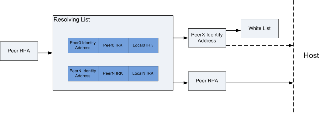
Figure 51. Resolving List.
If the controller is unable to resolve the peer RPAs, or the white list takes no actions for the incoming address, the address is still passed to the host. If the local device or peer device wishes, it can initiate a bonding sequence to exchange IRKs as well as device identity addresses. If these are exchanged, the host can use those parameters to update the controller’s resolving list, and even update the white list, so that the controller can automatically form a connection with the peer during a future connection attempt.
New HCI Commands
The following new HCI commands are now supported in the controller:
- LE Add Device to Resolving List Command
- LE Remove Device to Resolving List Command
- LE Clear Resolving List Command
- LE Read Resolving List Size Command
- LE Read Peer Resolvable Address Command
- LE Read Local Resolvable Address Command
- LE Set Address Resolution Enable Command
- LE Set Random Private Address Timeout Command
For additional details, please see Bluetooth Core_v4.2 specification (Vol 2, Part E, Section 7.8 for the commands, and Section 7.7 for the event).
Privacy and White List
Enabling Auto Sync of White List
The stack can automatically add devices to the white list after bonding. Use the following code to enable this syncing of the white list.
1 2 | uint8_t autoSyncWhiteList = TRUE;
GAPBondMgr_SetParameter(GAPBOND_AUTO_SYNC_WL, sizeof(uint8_t), &autoSyncWhiteList);
|
Using Resolvable Private Addresses
The device also can be configured to use a random address. Use GAP_ConfigDeviceAddr
to use random address. This API must be called after the GAP layer is started but cannot
be called during any BLE activity. In the function gapRole_processGAPMsg() add the
code below after gapRole_state = GAPROLE_STARTED:
//set address type to resolvable private address
status = GAP_ConfigDeviceAddr(ADDRMODE_PRIVATE_RESOLVE, NULL);
if (status != SUCCESS)
{
System_abort("Error!");
}
It can be verified with a sniffer that the address changes when advertising. The default timeout value between private (resolvable) address changes is 15 minutes. This can be modified by GAP_SetParamValue after calling GAP_ConfigDeviceAddr:
//Set timeout value to 5 minute
GAP_SetParamValue( TGAP_PRIVATE_ADDR_INT , 5);
// Update the advertising data
//...
Testing Privacy with White List
The following steps can be made to test the privacy with white list feature:
- Connect a iOS device to the CC13x0 both supporting Privacy 1.2.
- Pair with the device with the default passcode: 000000.
- The iOS devices should be automatically added to the white list.
- Disconnect and wait for the iOS device address to change.
- Reconnect to the CC13x0.
Logical Link Control and Adaptation Layer Protocol (L2CAP)
The L2CAP layer sits on top of the HCI layer on the host side and transfers data between the upper layers of the host (GAP, GATT, application) and the lower layer protocol stack. This layer is responsible for protocol multiplexing capability, segmentation, and reassembly operation for data exchanged between the host and the protocol stack. L2CAP permits higher-level protocols and applications to transmit and receive upper layer data packets (L2CAP service data units, SDU) up to 64KB long. See Figure 52. for more information.
Note
The actual size is limited by the amount of memory available on the specific device being implemented. L2CAP also permits per-channel flow control and retransmission.

Figure 52. L2CAP Architectural blocks.
General L2CAP Terminology
| Term | Description |
|---|---|
| L2CAP channel | The logical connection between two endpoints in peer devices, characterized by their Channel Identifiers (CIDs) |
| SDU or L2CAP SDU | Service Data Unit: a packet of data that L2CAP exchanges with the upper layer and transports transparently over an L2CAP channel using the procedures specified in this document |
| PDU or L2CAP PDU | Protocol Data Unit: a packet of data containing L2CAP protocol information fields, control information, and/or upper layer information data |
| Maximum Transmission Unit (MTU) | The maximum size of payload data, in octets, that the upper layer entity can accept (that is, the MTU corresponds to the maximum SDU size). |
| Maximum PDU Payload Size (MPS) | The maximum size of payload data in octets that the L2CAP layer entity can accept (that is, the MPS corresponds to the maximum PDU payload size). |
Maximum Transmission Unit (MTU)
The Bluetooth low energy stack supports fragmentation and recombination of L2CAP PDUs at the link layer. This fragmentation support allows L2CAP and higher-level protocols built on top of L2CAP, such as the attribute protocol (ATT), to use larger payload sizes, and reduce the overhead associated with larger data transactions. When fragmentation is used, larger packets are split into multiple link layer packets and reassembled by the link layer of the peer device. Figure 53. shows this relationship.

Figure 53. L2CAP Packet Fragmentation.
The size of the L2CAP PDU also defines the size of the Attribute
Protocol Maximum Transmission Unit (ATT_MTU). By default, LE
devices assume the size of the L2CAP PDU is 27 bytes, which
corresponds to the maximum size of the LE packet that can transmit
in a single connection event packet. In this case, the L2CAP
protocol header is 4 bytes, resulting in a default size for ATT_MTU
of 23.
Note
When using the LE Data Length Extension feature, the length of the LE packet can be up to 251 bytes. See LE Data Length Extension
Configuring for Larger MTU Values
A client device can request a larger ATT_MTU during a connection by
using the GATT_ExchangeMTU command.
During this procedure, the client informs the server of its maximum
supported receive MTU size and the server responds with its maximum supported
receive MTU size. Only the client can initiate this procedure. When
the messages are exchanged, the ATT_MTU for the duration of the
connection is the minimum of the client MTU and server MTU values.
If the client indicates it can support an MTU of 200 bytes and the
server responds with a maximum size of 150 bytes, the ATT_MTU size
is 150 for that connection.
For more information, see the MTU Exchange section of Specification of the Bluetooth System, Covered Core Package, Version: 4.2.
Take the following steps to configure the stack to support larger MTU values.
- Set the
MAX_PDU_SIZEpreprocessor symbol in the application project to the desired value to the maximum desired size of the L2CAP PDU size. The maximumATT_MTUsize is always 4 bytes less than the value of theMAX_PDU_SIZE. - Call GATT_ExchangeMTU after a connection is formed (GATT client only). The MTU parameter passed into this function must be less than or equal to the definition from step 1.
- Receive the
ATT_MTU_UPDATED_EVENTin the calling task to verify that the MTU was successfully updated. This update requires the calling task to have registered for GATT messages. See Registering to Receive Additional GATT Events in the Application for more information.
Though the stack can be configured to support a MAX_PDU_SIZE up to
255 bytes, each Bluetooth low energy connection initially uses the
default 27 bytes (ATT_MTU = 23 bytes) value until the exchange MTU
procedure results in a larger MTU size. The exchange MTU procedure
must be performed on each Bluetooth low energy connection and must
be initiated by the client.
Note
If the Secure Connections BLE 4.2 Feature is enabled, the default MTU size will be 69 upon connection.
See ble_user_config.h for details.
Increasing the size of the ATT_MTU increases the amount of data
that can be sent in a single ATT packet. The longest attribute that
can be sent in a single packet is (ATT_MTU-1) bytes. Procedures,
such as notifications, have additional length restrictions. If an
attribute value has a length of 100 bytes, a read of this entire
attribute requires a read request to obtain the first (ATT_MTU-1)
bytes, followed by multiple read blob request to obtain the
subsequent (ATT_MTU-1) bytes. To transfer the entire 100 bytes of
payload data with the default ATT_MTU = 23 bytes, five request or
response procedures are required, each returning 22 bytes. If the
exchange MTU procedure was performed and an ATT_MTU was configured
to 101 bytes (or greater), the entire 100 bytes could be read in a
single read request or response procedure.
Note
Due to memory and processing limitations, not all
Bluetooth low energy systems support larger MTU sizes. Know the
capabilities of expected peer devices when defining the behavior of
the system. If the capability of peer devices is unknown, design the
system to work with the default 27-byte L2CAP PDU/23-byte ATT_MTU
size. For example, sending notifications with a length greater than
20 bytes (ATT_MTU-3) bytes results in truncation of data on devices
that do not support larger MTU sizes.
L2CAP Channels
L2CAP is based around channels. Each endpoint of an L2CAP channel is referred to by a channel identifier (CID).See Volume 3, Part A, Section 2.1 of the Specification of the Bluetooth System, Covered Core Package, Version: 4.2 for more details on L2CAP Channel Identifiers. Channels can be divided into fixed and dynamic channels. For example, data exchanged over the GATT protocol uses channel 0x0004. A dynamically allocated CID is allocated to identify the logical link and the local endpoint. The local endpoint must be in the range from 0x0040 to 0xFFFF. This endpoint is used in the connection-orientated L2CAP channels described in the following section.
L2CAP Connection-Oriented Channel (CoC) Example
The Bluetooth low energy stack SDK provides APIs to create L2CAP CoC channels to transfer bidirectional data between two Bluetooth low energy devices supporting this feature. This feature is enabled by default in the protocol stack. Figure 54. shows a sample connection and data exchange process between master and slave device using a L2CAP connection-oriented channel in LE Credit Based Flow Control Mode.
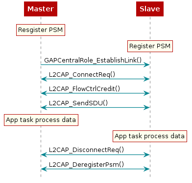
Figure 54. Sample Connection and Data Exchange Between a Master and Slave Device Using a L2CAP.
Connection-Oriented Channel in LE Credit Based Flow Control Mode
Credit Based Flow Control mode is used by the L2CAP layer for Connection-Oriented Channels.
For more information on these L2CAP APIs, refer to BLE-Stack API Reference.
LE Data Length Extension
Summary
The data length extension feature allows the LE controller to send data channel packet data units (PDUs) with payloads of up to 251 bytes of application data, while in the connected state. Furthermore, a new PDU size can be negotiated by either side at any time during a connection.
Previously, the controller’s largest data channel payload was 27 bytes. This increases the data rate by around 2.5*, compared to Bluetooth Core Specification version 4.0 and 4.1 devices (if both devices support extended packet length and are configured properly).
Data Length Update Procedure
Once a connection is formed, the controller will behave in one of two possible ways:
If prior to the connection, the suggested PDU size and time are set to the defaults for both TX and RX (27B, 328 us) then the CC13x0 will not initiate a data length exchange (i.e. a
LL_LENGTH_REQwill not be sent).If the peer device sends a
LL_LENGTH_REQthen the controller of the device will send aLL_LENGTH_RSPcorresponding to the default sizes of 4.0 devices autonomously.Note
See Utilizing the Feature at Run Time for information on how to get this behavior.
If prior to the connection, the PDU size or the maximum time for RX or TX are not default, then the LE controller of the device will use the
LL_LENGTH_REQandLL_LENGTH_RSPcontrol PDUs to negotiate a larger payload size for data channel PDUs.A data length update may be initiated by the host or performed autonomously by the controller. Either the master or the slave can initiate the procedure.
After the data length update procedure is complete, both controllers select a new data length based on two parameters: PDU size and time. The largest size supported by both local and remote controller is selected; time is taken into account to support different data rates. These parameters are defined below:
- PDU size
- The largest application data payload size supported by the controller. This size does not include packet overhead, such as access address or preamble.
- Time
- The maximum number of microseconds that the device takes to transmit or receive a PDU at the PHY rate. This parameter uses units of microseconds (us).
Note
Reference the Bluetooth Core Specification version 4.2 ([Vol 6], Part B, Section 5.1.9, Section 6.14) for more information about the data length update procedure.
See Table 14. for reference to the maximum sizes and times supported. The CC13x0 supports these maximum values.
| LE Data Packet Length Extensions Feature Supported | PDU Size in Octets | PDU Transmit Time (us) | ||
|---|---|---|---|---|
| Minimum | Maximum | Minimum | Maximum | |
| No | 27 | 27 | 328 | 328 |
| Yes | 27 | 251 | 328 | 2120 |
Initial Values
The controller defaults to using TX PDU sizes compatible with 4.0 and 4.1 devices. It uses 27 bytes as its initial maximum PDU size, and 328 us as the maximum PDU transmit time.
On the RX side, the controller defaults to the maximum PDU size and the maximum PDU transit time for a LE Data Packet Length Extension enabled device. In other words, the RX PDU size will be 251, and the RX PDU transmit time will be 2120 us.
Note
As mentioned in Data Length Update Procedure, by default
a LL_LENGTH_REQ control packet will be sent by the device due
to the RX max PDU size and max PDU transmit time not being default 4.0
PDU sizes and timings.
The application can update the data length in two ways.
- the application can set the connection initial max octets to cause the controller to request a larger size for every connection.
- the controller can initialize the connection with the default values of 27 octets and 328 us, then dynamically negotiate the data length at a later time in the connection.
For maximum throughput, high layer protocols such as the BLE host should also use a larger PDU size (see Maximum Transmission Unit (MTU)). Figure 55. illustrates various PDU sizes in the stack.
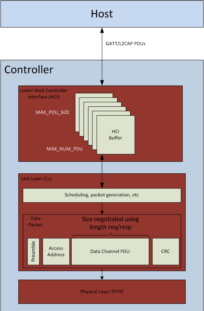
Figure 55. Various PDUs within the Stack
Data Length Extension HCI Commands and Events
The following HCI commands can be used to interact with the controller related to the data length extension feature:
- LE Read Suggested Default Data Length Command (HCI_LE_ReadSuggestedDefaultDataLenCmd)
- LE Write Suggested Default Data Length Command (HCI_LE_WriteSuggestedDefaultDataLenCmd)
- LE Read Maximum Data Length Command (HCI_LE_ReadMaxDataLenCmd)
- LE Set Data Length Command (HCI_LE_SetDataLenCmd)
The above commands may generate:
- LE Data Length Change Event
Note
For more information about these HCI commands and their fields, see Bluetooth Core Specification version 4.2 ([Vol 2], Part E, Section 7.7-7.8). Additionally, the APIs for these new commands are documented under BLE-Stack API Reference.
In addition to the Bluetooth SIG defined HCI commands, the following TI Vendor Specific command also interact with the controller related to the data length extension feature:
- HCI_EXT_SetMaxDataLenCmd
Utilizing the Feature at Run Time
As discussed in Initial Values, the LE controller initially uses packet length values compatible with 4.0 and 4.1 devices in new connections for TX. The controller will automatically attempt to negotiate a higher data length at the beginning of every new connection. To disable this feature, add the following call to the application task’s initialization routine (such as simple_peripheral_init).
1 2 3 4 5 6 7 8 | #define APP_TX_PDU_SIZE 27
#define APP_RX_PDU_SIZE 27
#define APP_TX_TIME 328
#define APP_RX_TIME 328
//This API is documented in hci.h
HCI_EXT_SetMaxDataLenCmd(APP_TX_PDU_SIZE , APP_TX_TIME,
APP_RX_PDU_SIZE, APP_RX_TIME);
|
Once a connection is formed, the controller handles negotiating a packet size with the peer device. If both devices are set up to use data length extension, a throughput increase is observed.
To re-enable controller negotiation upon a new connection, simply adjust the values to be greater using the same command above. Use valid values as shown in Table 14., otherwise the controller will reject this call.
In addition to the TI Vendor Specific command, Bluetooth SIG HCI commands can also be used, such as the following.
1 2 3 4 5 6 | #define APP_SUGGESTED_PDU_SIZE 251
#define APP_SUGGESTED_TX_TIME 2120
//This API is documented in hci.h
HCI_LE_WriteSuggestedDefaultDataLenCmd(APP_SUGGESTED_PDU_SIZE ,
APP_SUGGESTED_TX_TIME)
|
HCI_LE_WriteSuggestedDefaultDataLenCmd only alters the PDU size and time for the Transmit side.
Set Packet Length in a Connection
Packet length can also be changed dynamically in a connection using the below API snippet. The application can determine when this must occur based on any logic, such as sensor data or button presses.
uint16_t cxnHandle; //Request max supported size
uint16_t requestedPDUSize = 251;
uint16_t requestedTxTime = 2120;
GAPRole_GetParameter(GAPROLE_CONNHANDLE, &cxnHandle); //This API is documented in hci.h
if (SUCCESS != HCI_LE_SetDataLenCmd(cxnHandle, requestedPDUSize, requestedTxTime))
DISPLAY_WRITE_STRING("Data length update failed", LCD_PAGE0);
Host Controller Interface (HCI)
The host controller interface (HCI) layer is a thin layer which transports commands and events between the host and controller elements of the Bluetooth protocol stack. In a pure network processor application (that is, the host_test project), the HCI layer is implemented through a transport protocol such as SPI or UART.
In embedded wireless MCU projects such as simple_peripheral project, the HCI layer is implemented through function calls and callbacks within the wireless MCU. All of the commands and events discussed that communicate with the controller, such as ATT, GAP, etc, will eventually call an HCI API to pass from the upper layers of the protocol stack through the HCI layer to the controller. Likewise, the controller sends received data and events to the host and upper layers through HCI.
As well as standard Bluetooth LE HCI commands, a number of HCI extension vendor-specific commands are available which extend some of the functionality of the controller for use by the application. See HCI for a description of available HCI and HCI extension commands callable in the embedded application.
The BLE-Stack supports a network processor configuration (host_test) that allows an application to running on an external MCU to interface to the BLE-Stack. The network processor can accept all LE HCI commands over a external transport protocol (UART, SPI, etc); however, because the BLE host and controller both reside on the wireless MCU, some HCI commands will have their corresponding events consumed by the TI BLE host. Thus, it is not possible to interface an external, off-chip Bluetooth host to the CC13x0 wireless MCU using standard HCI LE commands. Network processor configurations should use both HCI and TI vendor-specific HCI commands to implement an external Bluetooth application.
Similar to a network processor configuration (host_test), the BLE-Stack can be configured to be pass a subset HCI commands from a transport protocol (UART, SPI, etc) to the controller with the ability to switch to an intact embedded application. This configuration is known as Production Test Mode (PTM). The subset of HCI commands available are those to perform Bluetooth RF certification.
PTM should be considered for use for Direct Test Mode (DTM) in place of a full network processor configuration (host_test) when the following is required:
Device is only Flashed Once during the production line
If product flashing is only done once or production firmware is flashed prior to testing Bluetooth RF Functionality, and firmware images can no longer be changed.
Flash Availability for HCI Transport Layer
PTM requires flash along side the application, thus reducing application flash.
Using HCI and HCI Vendor-Specific Commands in the Application
Follow these steps to use these commands and receive their respective events in the application:
- Include the HCI transport layer header file.
- Register with GAP for HCI/Host messages in order to receive events from the controller. This should be done in the application initialization function.
- Call any HCI or HCI vendor-specific command that is able to be called the application. See the HCI section for a table of which commands can be sent.
- HCI events are returned as inter-task messages as a HCI_GAP_EVENT_EVENT. See the simple_peripheral project for an example of this.
The following sections consider receiving HCI events and HCI vendor-specific events.
Standard LE HCI Commands and Events
These commands are documented in Volume 2, Part E, Section 7 of the 4.2 Core Spec. The mechanism to use these commands is the same for any command in this section of the core spec, including HCI LE commands. The example below demonstrates how to use the core spec to implement an HCI command in the application. The command considered is Read RSSI Command.
Sending an HCI Command
- Find the command in the core spec:
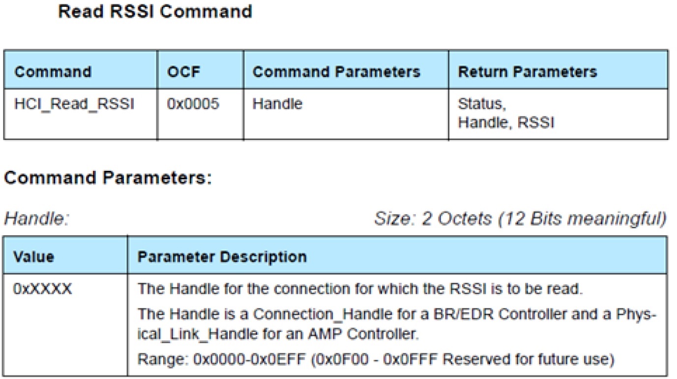
Figure 56. RSSI Command from the BLE Core Specifications.
- Find mapping to BLE stack command. Using the BLE-Stack API Reference, shows that this command maps to HCI_ReadRssiCmd().
- Using the API from Step 1, fill in the parameters and call the command from somewhere in the application. This specific command should be called after a connection is formed. There is only command parameter here: a 2-byte connection handle. In the case of this example, the connection handle is 0x0000:
Receiving HCI Events
Tip
Make sure to register for messages; or no event messages will be sent to your task.
Register with GAP for HCI/Host messages with: GAP_RegisterForMsgs()
Look at the core spec to see the format of the returned event:
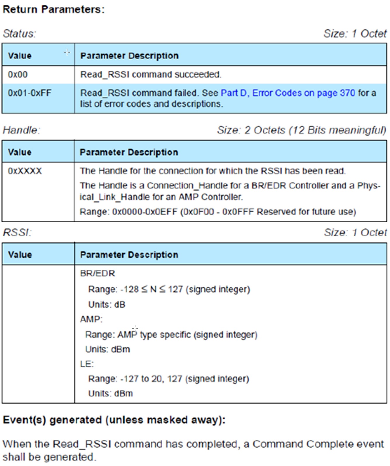
Figure 57. RSSI Return information with Event from the BLE Core Specifications.
This command returns a Command Complete event (hciEvt_CmdComplete_t) as stated in the “Corresponding Events” section of the doxygen API ( HCI_ReadRssiCmd ), so add this as a case in the processing of HCI_GAP_EVENT_EVENT. This is further detailed below.
1 2 3 4 5 6 7 8 9 10 11 12 13 14 15 16 17 18 19 20 21 22 23 24 25 26 27 28 29 30 31
static uint8_t SimpleBLEPeripheral_processStackMsg(ICall_Hdr* pMsg) { uint8_t safeToDealloc = TRUE; switch (pMsg->event) { case HCI_GAP_EVENT_EVENT: { // Process HCI message switch(pMsg->status) { // Process HCI Command Complete Event case HCI_COMMAND_COMPLETE_EVENT_CODE: { // Parse Command Complete Event for opcode and status hciEvt_CmdComplete_t* command_complete = (hciEvt_CmdComplete_t*) pMsg; uint8_t status = command_complete->pReturnParam[0]; //find which command this command complete is for switch (command_complete->cmdOpcode) { case HCI_READ_RSSI: { if (status == SUCCESS) { uint16_t handle = BUILD_UINT16( command_complete->pReturnParam[2], command_complete->pReturnParam[1]); //check handle if (handle == 0x00) { //store RSSI uint8_t rssi = command_complete->pReturnParam[3];
First, the status of the stack message is checked to see what type of HCI event it is. In this case, it is an HCI_COMMAND_COMPLETE_EVENT_CODE. Then the event returned from the stack as a message (pMsg) is cast to an hciEvt_CmdComplete_t, which is defined as:
Next, the cmdOpcode is checked and it is found that it matches HCI_READ_RSSI. Then the status of the event is checked. Now that the event is known, the pReturnParmam can be parsed using the information from the core spec. The core spec API from above states that the first byte of the return parameters is the Status.
The core spec API states that the second and third bytes of the return parameters are the Handle. The RSSI is then checked to see if it corresponds to the desired connection handle.
Continuing parsing using the core spec API, the RSSI value can be found by reading the fourth byte of the return paramters. Finally, the RSSI value is stored.
HCI Vendor-Specific Commands
These commands are documented in the TI Vendor Specific HCI Guide. The mechanism to use these commands is the same for all vendor-specific commands. The example below demonstrates how to use the TI Vendor Specific HCI Guide to implement an HCI command in the application. The command considered is HCI Extension Packet Error Rate.
Sending HCI Vendor-Specific Command
Find the command in the TI BLE vendor-specific guide:
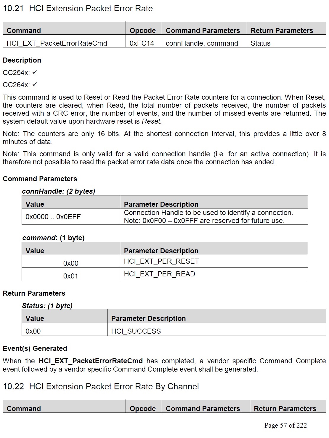
Figure 58. Packet Error Rate Cmd from HCI Vendor-Specific Commands Guide.
Use the HCI to find the BLE Stack function that implements this command : HCI_EXT_PacketErrorRateCmd.
Using the API from Step 1, fill in the parameters and call the command from the application. In this specifica case, this command should be called after a connection has been formed. The first parameter is a 2-byte connHandle, which is 0x0000 for this example. The second parameter is a 1-byte command ( HCI_EXT_PER_READ ) to read the counters. Therefore, use:
Receiving HCI Vendor-Specific Events
Find the corresponding event in the TI Vendor Specific HCI Guide
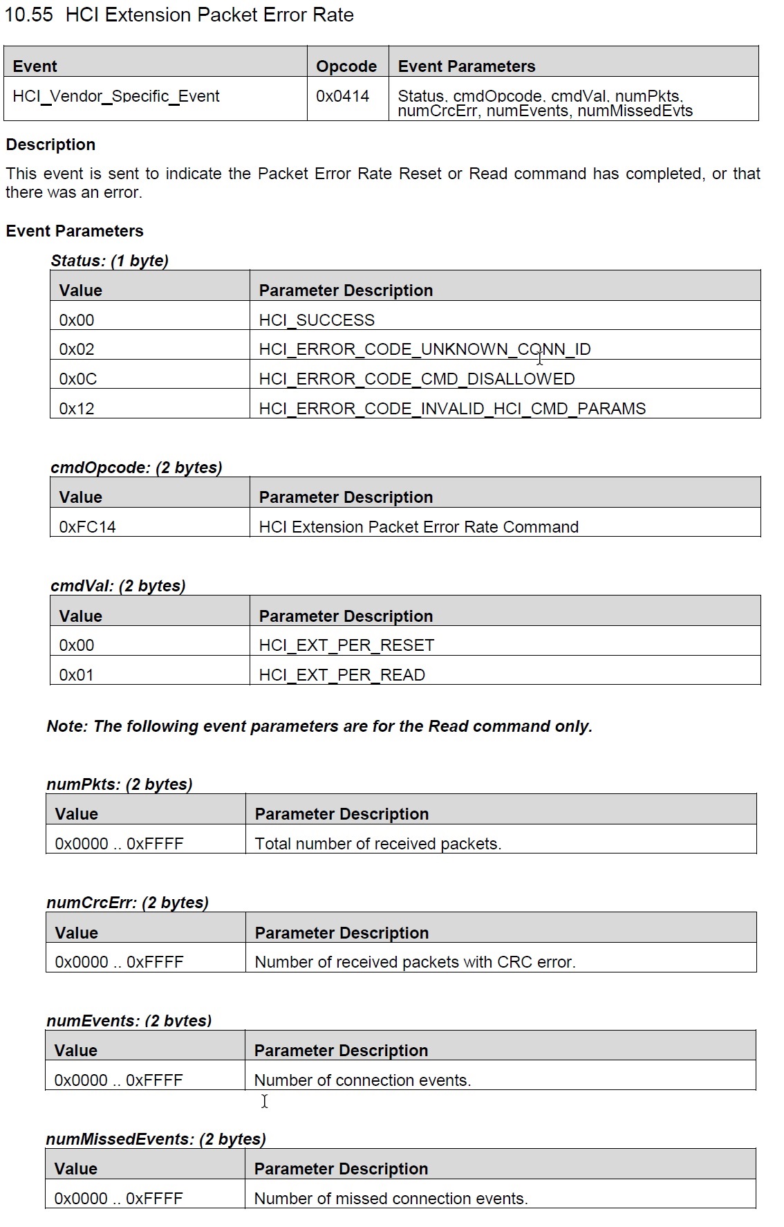
Figure 59. Packet Error Rate Event from HCI Vendor-Specific Commands Guide.
As stated in the “Corresponding Events” section of the command API, this command returns a Vendor Specific Command Complete Event ( hciEvt_VSCmdComplete_t ) Therefore, add this as a case in the processing of HCI_GAP_EVENT_EVENT processing. This is further detailed below.
1 2 3 4 5 6 7 8 9 10 11 12 13 14 15 16 17 18 19 20 21 22 23 24 25 26 27 28 29 30 31 32
static uint8_t SimpleBLEPeripheral_processStackMsg(ICall_Hdr* pMsg) { uint8_t safeToDealloc = TRUE; switch (pMsg->event) { case HCI_GAP_EVENT_EVENT: { // Process HCI message switch(pMsg->status) { // Process HCI Vendor Specific Command Complete Event case HCI_VE_EVENT_CODE: { // Parse Command Complete Event for opcode and status hciEvt_VSCmdComplete_t* command_complete = (hciEvt_VSCmdComplete_t*)pMsg; // Find which command this command complete is for switch(command_complete->cmdOpcode) { case HCI_EXT_PER: { uint8_t status = command_complete->pEventParam[2]; if (status == SUCCESS) { uint8_t cmdVal = command_complete->pEventParam[3]; if (cmdVal == 1) //if we were reading packet error rate { uint16_t numPkts = BUILD_UINT16(command_complete->pEventParam[5], command_complete->pEventParam[4]); uint16_t numCrcErr = BUILD_UINT16(command_complete->pEventParam[7], command_complete->pEventParam[6]); uint16_t numEvents = BUILD_UINT16(command_complete->pEventParam[9], command_complete->pEventParam[8]); uint16_t numMissedEvents = BUILD_UINT16(command_complete->pEventParam[11], command_complete->pEventParam[10]);
First, the status of the stack message is checked to see what type of HCI event it is. In this case, it is an HCI_VE_EVENT_CODE.
Next, the event returned from the stack as a message (pMsg) is cast to an hciEvt_VSCmdComplete_t, which is defined as:
1 2 3 4 5
typedef struct
{
   osal_event_hdr_t hdr; uint8 length;
   uint16 cmdOpcode; uint8* pEventParam;
} hciEvt_VSCmdComplete_t;
The opcode is checked by reading command_complete->cmdOpcode, and found that it matches HCI_EXT_PER.
Next, the *pEventParam is parsed to extract the parameters defined in the event API. The first two bytes (shown in red in Figure 60.) are the event opcode (0x1404). The third byte is the Status. This is the case for all vendor-specific events.
From the fourth byte of pEventParam on, the event API from the TI BLE Vendor-Specific Guide is used for parsing, starting at the third parameter. This is the case for all vendor-specific events. For this example, the fourth byte of pEventParam corresponds to the cmdVal parameter. This is shown in memory and explained further below.
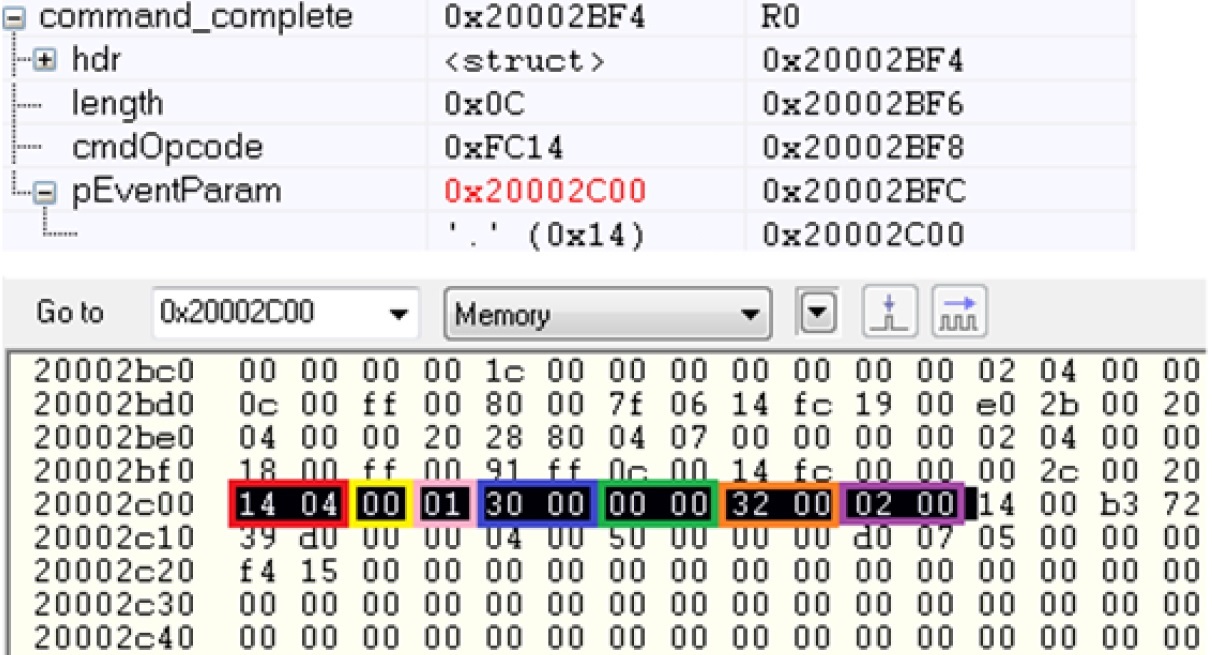
Figure 60. RSSI Commend from the BLE Core Specifications.
The status is checked by reading the third byte of the event parameters (command_complete->pEventParam[2]). This is shown in yellow in Figure 60..
Starting from the fourth byte of the event parameters (command_complete->pEventParam[3]), the event API states that the next parameter is a one-byte cmdVal. This is checked to verify that this event corresponds to a read of the PER counters. This is shown in pink.
Continuing parsing using the event API, the next parameter is a two-byte numPkts. This is found by building a uint16_t out of the fifth and sixth bytes of the event parameters. This is shown in blue. In a similar fashion, numCrcErr is found from the seventh and eight bytes of the event parameters (shown in green).
Next, numEvents is found from the ninth and tenth bytes of the event parameters (shown in orange). Finally, numMissedEvents is found from the eleventh and twelfth bytes of the event parameters (shown in purple).
Creating a Custom Bluetooth low energy Application
A system designer must have a firm grasp on the general system architecture, application, and Bluetooth low energy stack framework to implement a custom Bluetooth low energy application. This section provides indications and guidance on where and how to start implementing a custom application based on information presented in the previous sections (The Application and The Stack) as well as knowledge of TI RTOS and CC13x0. A good starting point is deciding what role and purpose the custom application will have.
Defining Application Behavior
The Sample Applications will often contain simple RTOS tasks with a bare-bones messaging system between tasks. For more information on how the application tasks works in general, review The Application.
To add drivers for other peripherals, see Drivers.
Creating Additional ICall Enabled Tasks
The objective of this section is to familiarize the programmer with the process of adding an RTOS task that can communicate with the BLE-Stack. Tasks that call functions within the BLE-Stack must follow a few additional steps to register with ICall. These details are covered below:
1. Follow all the steps detailed in Tasks to create a TI-RTOS task.
- Modify the task’s init function to register with ICall (explained in ICall Initialization and Registration)
- Modify the task’s main function to pend on ICall (explained in ICall Thread Synchronization)
- Modify the number of ICall enabled tasks:
- Increase the following preprocessor define:
- ICALL_MAX_NUM_TASKS (App)
- See Accessing Preprocessor Symbols (CCS) and Accessing Preprocessor Symbols (IAR) for steps on how to change symbols
- Modify the number of ICall entities:
- Increase the following preprocessor define:
- ICALL_MAX_NUM_ENTITIES (App)
For further description of the above preprocessor defines, please see Table 16.
Optimizing Bluetooth low energy Stack Memory Usage
Configuration of the Bluetooth low energy protocol stack is essential for maximizing the amount of RAM and flash memory available for the application. Refer to Stack Configurations to configure parameters that impact runtime RAM usage, such as the maximum allowable size and number of PDUs. The TI Bluetooth low energy protocol stack is implemented to use a small RAM footprint, and allow the application to control the behavior of the stack by using the runtime ICall heap. For example, an application that only sends one GATT notification per connection event must store only one PDU in the heap, whereas as an application that must send multiple notifications must enqueue multiple PDUs in the heap.
To increase the available flash memory allocated to the application project, minimize the flash usage of the protocol stack by including only Bluetooth low energy features required to implement the defined role of the device. The available protocol stack configurable features are described in Stack Configurations. Adding additional features to the protocol stack has the net effect of reducing the amount of flash memory to the application.
Additional Memory Configuration Options
The following tips can be used to minimize RAM and flash usage by the protocol stack:
- Verify that your application uses the optimize for flash size compiler optimization settings (default for TI projects).
- Use only one page of SNV, or if the GAP bond manager is not required do not use any NV pages. To use no NV pages, set the
NO_OSAL_SNVstack preprocessor option. See Using Simple NV for Flash Storage for a description of the SNV.- Exclude the GATT client functionality by defining the
GATT_NO_CLIENTpredefined symbol in the stack project for peripheral devices. (Peripheral devices do not typically implement the GATT client role.)- Remove or exclude debug DISPLAY drivers from the application project (see Dynamic Allocation Errors).
- Exclude Bluetooth low energy features from the Bluetooth low energy stack that are not used.
See Check System Flash and RAM Usage With Map File for the procedure to check the size of the configured protocol stack.
Defining Bluetooth Low Energy Behavior
This step involves using Bluetooth low energy protocol stack APIs to define the system behavior and adding profiles, defining the GATT database, configuring the security model, and so forth. Use the concepts explained in The Stack as well as the Bluetooth low energy API reference in BLE-Stack API Reference.
Stack Configurations
Configuring Bluetooth Low Energy Protocol Stack Features
The Bluetooth Low Energy protocol stack can be configured to include
or exclude certain Bluetooth Low Energy features by changing the
library configuration in the stack project. The available Bluetooth
Low Energy features are defined in the build_config.opt file in
the Tools folder of the stack project within the IDE. Based on the
features selected in the build_config.opt file, the lib_search.exe tool
selects the respective precompiled library during the build process of the
stack project.
Table 15. lists a summary of
configurable features. See the build_config.opt file
for additional details and supported configurations.
| Feature | Description |
|---|---|
| HOST_CONFIG | This option configures the stack’s host layer based on its targeted GAP role.
These combo roles are supported:
- PERIPHERAL_CFG+OBSERVER_CFG
- CENTRAL_CFG+BROADCASTER_CFG
- PERIPHERAL_CFG+CENTRAL_CFG
- BROADCASTER_CFG+OBSERVER_CFG
|
| BLE_V41_FEATURES | Features supported from the Bluetooth Low Energy core specification v4.1.
These features include:
- Ping (V41_CTRL_CFG)
- Slave feature exchange (V41_CTRL_CFG)
- Connection parameter update request (V41_CTRL_CFG)
- Multirole connections (V41_CTRL_CFG)
- L2CAP Connection Oriented Channels (L2CAP_COC_CFG)
|
| BLE_V42_FEATURES | Features supported from the Bluetooth Low Energy core specification v4.2.
These include:
- Data Length Extension (EXT_DATA_LEN_CFG)
- Secure Connections (SECURE_CONNS_CFG)
- Privacy 1.2 (PRIVACY_1_2_CFG)
|
| HCI_TL_xxxx | Include HCI Transport Layer (FULL, PTM or NONE). |
Note
Selecting the correct stack configuration is essential in optimizing the amount of flash memory available to the application. To conserve memory, exclude certain Bluetooth Low Energy protocol stack features that may not be required.
Run-Time Bluetooth low energy Protocol Stack Configuration
The Bluetooth low energy protocol stack can be configured with
various parameters that control its runtime behavior and RF antenna
layout. The available configuration parameters are described in the
ble_user_config.h file in the ICallBLE IDE folder of the
application. During initialization, these parameters are supplied to
the Bluetooth Low Energy protocol stack by the user0Cfg structure,
declared in main.c.
#include "ble_user_config.h"

// BLE user defined configuration
bleUserCfg_t user0Cfg = BLE_USER_CFG;
Because the ble_user_config.h file is shared with projects within
the SDK, TI recommends defining the configuration parameters in the
preprocessor symbols of the application when using a non default
value. For example, to change the maximum PDU size from the default
27 to 162, set the preprocessor symbol MAX_PDU_SIZE=162 in the
preprocessor symbols for the application project. Increasing certain
parameters may increase heap memory use by the protocol stack;
adjust the HEAPMGR_SIZE as required (if not using auto sized heap). Table 16. lists the available configuration parameters.
| Parameter | Description |
|---|---|
| MAX_NUM_BLE_CONNS | Maximum number of simultaneous Bluetooth low energy connections. Default is 1 for Peripheral and Central roles. Maximum value is based on GAPRole. |
| MAX_NUM_PDU | Maximum number of Bluetooth low energy HCI PDUs. Default is 5. If the maximum number of connections is set to 0, then this number should also be set to 0. |
| MAX_PDU_SIZE | Maximum size in bytes of the Bluetooth low energy HCI PDU. Default is 27. Valid range is 27 to 255. The maximum ATT_MTU is MAX_PDU_SIZE - 4. See Configuring for Larger MTU Values. |
| L2CAP_NUM_PSM | Maximum number of L2CAP Protocol/Service Multiplexers (PSM). Default is 3. |
| L2CAP_NUM_CO_CHANNELS | Maximum number of L2CAP Connection-Oriented (CO) Channels. Default is 3. |
| PM_STARTUP_MARGIN | Defines time in microseconds (us) the system will wake up before the start of the connection event. Default is 300. This value is optimized for the example projects. |
| RF_FE_MODE_AND_BIAS | Defines the RF antenna front end and bias configuration. Set
this value to match the actual hardware antenna layout. This
value can be set directly, or through Board.h. For more
information see
Configuring the RF Front-End for Custom Hardware |
| ICALL_MAX_NUM_TASKS (App) OSAL_MAX_NUM_PROXY_TASKS (Stack) | Defines the max number of ICall enabled tasks. These defines, although on different sides, (app and stack), must be the same. OSAL_MAX_NUM_PROXY_TASKS defaults to 2. ICALL_MAX_NUM_Tasks defaults to 2. |
| ICALL_MAX_NUM_ENTITIES (App) | This Maximum number of entities that use ICall, including service entities and application entities. |
Warning
TI Recommends limiting the number of ICall enabled tasks due to resource usage. For more information on creating ICall enabled tasks, see Adding ICall RTOS Tasks
Running the SDK on Custom Boards
This section will explain how to adapt a BLE application from the SimpleLink CC13x0 SDK to run on custom hardware. In general, the steps required to migrate a BLE application from a development kit to a custom board are minimal and involve changing the pin configuration as well as selecting the correct RF configuration. These steps, including a bring up guide, are detailed in the subsections below.
TI Provided Board Files
In order to make the SimpleLink CC13x0 SDK’s sample applications portable across different board and package types, a high level gateway file is used to select the proper board file based on the <board_type> predefined symbol. The top-level board file (board.c) then uses this symbol to include the correct board file into the project. This top-level board file can be found at <SDK_INSTALL_DIR>\source\ti\blestack\target\board.c, and is located under the Startup folder in the project workspace.
The board file links in another gateway board file located at <SDK_INSTALL_DIR>\source\ti\blestack\target\<kit_type>, which finally links in the actual board file from <SDK_INSTALL_DIR>\source\ti\boards\<board_type>.
<kit_type> indicates a handful of reference board files supported by the SimpleLink CC13x0 SDK such as:
- cc1350lp
Warning
The <kit_type> is an intermediate step within the board gateway and will not need to be modified by the user while running on a TI EM or LP. Don’t try to set <kit_type> as a predefined symbol in your application.
The <board_type> define is set by the app project’s predefined symbols. The following defines are supported by the SimpleLink CC13x0 SDK and refer to a reference design (EM or LaunchPad) created by TI.
By changing the define above, the application project will pull in a board file that is adopted for the TI reference designs or development kits with same name. Click the links above for more information on their respective TI reference designs.
Note that within the <board_name>.h file the symbol used to select the board’s
the RF front end configuration will be defined. See ble_user_config.h and
Configuring the RF Front-End for Custom Hardware for more
information on available RF front end configurations.
Package Type and Board Files
Most of the examples within the SimpleLink CC13x0 SDK will run on the CC1350 Launchpad out of the box. Board files based on the TI CC26xx evaluation module (EM) reference designs are also provided for your convenience. (See TI Provided Board Files for more info) However, for custom hardware designs it may be necessary to modify the provided board files based on your selected package and RF configuration.
The board file for CC1350 Launchpad is made for the 7x7 mm QFN package using differential RF front end and internal biasing. To convert this board file to use for other smaller device packages (5x5 mm and 4x4 mm QFN), the board file will need to be modified since limited number of IO pins are available in the smaller packages.
Note
It is recommended to start customizing board file(s) based on a reference design that is most similar to your selected package type and RF configuration.
Refer to the datasheet for all the package options and IO descriptions: CC13x0 Technical Reference Manual
For example, to change to the 4x4 package, remove all defines for all IOs not available (IOID_10 and higher) since the 4x4 package has only 10 DIO pins as listed in the datasheet.
The table below shows the number of GPIOs supported by each package:
| Package Option | Total GPIO Pins | MAX IOID |
|---|---|---|
| 7x7 mm QFN | 31 | IOID_30 |
| 5x5 mm QFN | 15 | IOID_14 |
| 4x4 mm QFN | 10 | IOID_9 |
Creating a Custom Board File
TI-RTOS drivers rely on “board files” for their board-specific configuration
parameters. The convention is to name these files based on the development kits
provided by TI in addition to a generic Board.h with Board_* definitions
to map the proper pins defined by ioc.h.
For example, for the simple_peripheral project, the following comprise the set of board files used by the CC13x0 LaunchPad development kit:
- Board.h
- CC13x0_LAUNCHXL.h
- CC13x0_LAUNCHXL.c
Note
simple_peripheral board files are located in
<SDK_INSTALL_DIR>\source\ti\boards\CC1350\_LAUNCHXL
TI recommends to start with these existing set of board files when porting a BLE application to custom development boards. When modifying or porting these board files, user should consult with TI Driver APIs.
Tip
Board files provided by TI include TI-RTOS driver configuration data structures for various drivers. If the application does not use the associated TI-RTOS drivers, the linker will simply omit them from the application image.
The following steps provide guidance on customizing board files for a BLE-Stack 2.03.03 project.
Duplicate existing board files from existing CC13x0_LAUNCHXL board files.
- These files can be found at:
<SDK_INSTALL_DIR>\source\ti\boards\CC1350_LAUNCHXL - Create a copy of the
CC1350_LAUNCHXLdirectory and give it a unique meaningful name for your development platform. In this example, we call itMYBOARD.
Caution
The SimpleLink CC13x0 SDK also contains board files for TI-RTOS kernel and driver examples. These are not compatible with the BLE-Stack 2.03.03 because of differences in RF driver SWI priorities and custom drivers (e.g. TRNG) required by the BLE-Stack For BLE-Stack 2.03.03 projects, use the files specified above for reference from simple_peripheral.
- In the
MYBOARDdirectory, renameCC1350_LAUNCHXL.candCC1350_LAUNCHXL.hto theirMYBOARD.candMYBOARD.hrespectively. - Search and replace all references of
CC1350_LAUNCHXLwithMYBOARDinBoard.h,MYBOARD.candMYBOARD.h.
- These files can be found at:
Add a new preprocessor define in your project’s
board.candboard.hfiles.Continuing with the
MYBOARDexample, modifyboard.candboard.hin<SDK_INSTALL_DIR>\source\ti\targetReplace
CC1350_LAUNCHXLbyMYBOARDin your project’s application predefined symbols (See Accessing Preprocessor Symbols or Accessing Preprocessor Symbols)In
board.h, add the highlighted lines shown below:1 2 3 4
#elif defined(CC1350_LAUNCHXL)
    #include "./cc1350lp/cc1350lp_board.h"
#elif defined(MYBOARD)
    #include "../../boards/MYBOARD/MYBOARD.h"
In
board.c, add the highlighted lines shown below:1 2 3 4 5
#elif defined(CC1350_LAUNCHXL)
    #include "./cc1350lp/cc1350lp_board.c"
#elif defined(MYBOARD)
    #include "../../boards/MYBOARD/Board.h"
    #include "../../boards/MYBOARD/MYBOARD.c"
Explicit references to
CC1350_LAUNCHXL.hneed to be replaced byMYBOARD.h
Modify board files to match application requirements
- PIN structure to match the layout of the board. See Package Type and Board Files.
- Add peripheral driver initialization objects according to the board design. See Drivers for more information on drivers.
- For RF driver configuration, see Configuring the RF Front-End for Custom Hardware
Board Level Middleware
There are also several board driver files which are a layer of abstraction on top of TI-RTOS drivers, to function for a specific board, for example Board_key.c, or ExtFlash.c If desired, these files can be adapted to work for a custom board.
Using 32-kHz Crystal-Less Mode
BLE-Stack 2.03.03 includes support for operating the CC13x0 in a 32-kHz crystal-less mode for peripheral and broadcaster (beacon) role configurations. By using the internal low-frequency RC oscillator (RCOSC_LF), the 32-kHz crystal can be removed from the board layout.
There are a few steps that must be taken to enable this feature. For any peripheral project, the following change is required for IAR. For CCS user, please see the Running Bluetooth Low Energy on CC2640 Without 32 kHz Crystal for the needed steps to enable RCOSC_LF in your project. You will find more detail regarding this feature in the aforementioned application note.
Include rcosc_calibration.c, rcosc_calibration.h and ccfg_app_ble_rcosc.c files which locate at <SDK_INSTALL_DIR>\source\ti\blestack\common\cc26xx\rcosc
Exclude ccfg_app_ble.c from build.
Add USE_RCOSC to Defined symbols.
Add the following code to your peripheral project.c
#ifdef USE_RCOSC
#include "rcosc_calibration.h"
#endif //USE_RCOSC
Add the following code to your peripheralproject_init function in peripheral project.c
#ifdef USE_RCOSC
RCOSC_enableCalibration();
#endif // USE_RCOSC
If using a custom board file, enable the RCOSC in the power policy. The board files included with the BLE-Stack:
PowerCC26XX_Config PowerCC26XX_config = {
  .policyInitFxn     = NULL,
  .policyFxn         = &PowerCC26XX_standbyPolicy,
  .calibrateFxn      = &PowerCC26XX_calibrate,
  .enablePolicy      = TRUE,
  .calibrateRCOSC_LF = TRUE,
  .calibrateRCOSC_HF = TRUE,
};
Constrain the temperature variation to be less than 1°C/sec. If the temperature is to change faster than 1°C/sec, then a short calibration interval must be used. Calibration interval can be tuned in rcosc_calibration.h
// 1000 ms
#define RCOSC_CALIBRATION_PERIOD   1000
Note
Use of the internal RCOSC_LF requires a sleep clock accuracy (SCA) of 500 ppm.
Configuring the RF Front-End for Custom Hardware
The CC13x0 supports multiple RF front end options to optimize performance or cost. Reference designs are available for multiple RF front end options to aid in decoupling and RF layout. In order to achieve optimal sensitivity, it is important to configure the BLE application with the correct RF front end setting used on the custom board. An incorrectly configured RF front end may result in substantially degraded RF performance such as the inability to maintain a connection with a peer device. Configuration of the Front-EndRF front end is done within the board file.
For example, within the simple_peripheral project, the RF front end
configuration is defined in CC1350_LAUNCHXL.h with:
#define CC1350LP_7XD
The defined symbol is used in ble_user_config.h and ble_user_config.c
to set the correct RF Front end mode, and the select the appropriate PA table
for that configuration. In ble_user_config.h, CC1350LP_7XD is processed to
define RF_FE_MODE_AND_BIAS:
This configures the project to use a differential RF with external bias.
Other configurations can also be found in ble_user_config.h, select the
configuration appropriate to your project.
In ble_user_config.c, CC1350LP_7XD selects the appropriate PA table,
in this case for differential RF. For CC13x0, there are three PA tables,
one for differential operation on QFN packages, one for single ended on QFN,
and one for single ended on WCSP.
Note
There are several other parameters being configured in ble_user_config.
For CC13x0 it is only the RF front end mode and PA table that have to be
changed for different boards.
For information on front ends and antenna configurations, see CC26xx RF FrontEnds and Antennas.
For information on other hardware considerations, see TI Bluetooth Low Energy Wiki.
Configuring Device Parameters for Custom Hardware
- Set parameters, such as the sleep clock accuracy of the 32.768-kHz crystal. See HCI_EXT_SetSCACmd
- Define the CCFG parameters in ccfg_app_ble.c to enable or disable the ROM serial bootloader, JTAG access (DAP), flash protection, and so forth.
Note
For a description of CCFG configuration parameters, see the CC13x0 Technical Reference Manual.
Initial Board Bring Up
When powering up a custom board with the CC13x0 for the first time, it is recommended to complete the HW checklist items on the TI BLE Wiki. After confirming that the board is being powered correctly by the battery or power supply and can be identified by the JTAG tool, programming the device with a minimal SW application to verify stability is also suggested.
TI recommends using the simple_peripheral sample application for initial board bring up with modifications to the board file to:
- Disable all GPIO pin access
- Select the correct RF front end setting.
To disable all GPIO pin configuration, set the BoardGpioInitTable in the
board file to PIN_TERMINATE:
The TI BLE-Stack does not require any GPIO pins to be configured in order to
establish and maintain a BLE connection. Ensure that Display_DISABLE_ALL
is defined in the application Predefined Symbols so that diagnostic logging
data is not routed to any GPIO pin. If your custom board uses a different device
configuration, such as the 32 kHz crystal-less RCOSC_LF configuration, be sure
to make these device changes to the project. With this minimal application
configuration you should be able to establish a BLE connection
(e.g., with a smart phone or BTool) to your board at the expected range.
If you are not able to complete this step, then it is likely there is a
misconfiguration of the RF front end or you have other board related or layout
issues. Refer to the hardware troubleshooting tips on the TI BLE Wiki.
After confirming that your board can maintain a BLE connection, you can now validate that your BLE application functions as expected on the custom board. Again, it is suggested to enable your GPIO pins one at a time in the board file and comment-out access to other GPIO pins in your application. If you do encounter a CPU exception (HWI abort) during this phase it is likely that a GPIO pin is incorrectly mapped in your custom board file or your application is attempting to access a GPIO pin that does not exist in your device package type.