9. Examples and Demonstrations
9.1. Image Processing Demo
9.1.1. Introduction
This page describes the image processing demo provided in the Processor-SDK for RTOS. This demo illustrates the integration of key components in the SDK and provides a framework for application development.
The use case implemented is the transfer of image data from/to DDR and internal memory. Typically, images are large and need to be stored in external memory. Key functions include
- Operates on different segments of the same image in different cores
- Operates across multiple cores executing different algorithms on the same image data
- Transfers input/output image to a medium (SD card or external system)
- Utilize IPC to communicate between cores to perform an image processing task parallel
This demo utilizes many SDK features/components:
- Multi-core application utilizing ARM-A15 and DSP-C66x cores
- IMGLIB for optimized C66x image processing
- IPC for interprocessor communication
- NDK application utilizing NDK for internet access
- UIA for instrumentation logging
This demo is not available for all devices. Currently, the following devices and EVM are supported:
- AM57x, on the AM572x GP EVM
- C665x, on the C665x EVM
- C667x, on the C667x EVM
- K2H, on the K2H EVM
Note
Before running image demo for AM572x and K2H platforms on arm and c66x core , we need to increase stack size in netctrl.c file from 2048 to 4096 and rebuild the NDK library and driver, otherwise the demo fails
Note
This demo has been only verified with the Microsoft Internet Explorer
9.1.2. Requirements
The following materials are required to run this demonstration:
Hardware
- TI EVM (see list above)
- Local Area Network with DHCP support
- JTAG Emulator (on board or external)
Software
- Processor-SDK RTOS
- Code Composer Studio
9.1.3. Software Design
9.1.3.1. More about processing algorithms
The application will use IMGLIB APIs for its core image processing needs. The following steps are performed for edge detection:
- Split input image into multiple overlapping slices
- If it is a RGB image, separate out the Luma component (Y) for processing (See YCbCr for further details)
- Run Sobel operator (IMG_sobel_3x3_8) to get the gradient image of each slices
- Run the thresholding operation ( IMG_thr_le2min_8) on the slices to get the edges
- Combine the slices to get the final output
9.1.3.2. Framework for multicore
The current framework for multicore is IPC (Message Queue). The following are the overall steps (the master and threads will be run on one or more cores):
- The master thread will preprocess the input image to make a gray scale or luma image
- The master thread signal each slave thread to start processing and wait for processing complete signal from all slave threads
- The slave threads run edge detection function to generate output edge image of the slice
- Then the slave threads signal master thread indicating the processing completed
- Once master thread receives completion signal from all threads it proceeds with further user interface processing
9.1.3.3. How to Build the Demo
9.1.3.3.1. AM572x GP EVM
For Linux:
- Under ~/ti/processor_sdk_rtos_am57xx_3_01_xx_xx directory, run the following commands:
source ./setupenv.sh
make demo_clean
make demo
the OUT files for A15, DSP1 and DSP2 will be built at
   ~/ti/processor_sdk_rtos_am57xx_3_01_xx_xx/demos/image_processing/ipc/evmam572x/host/build,
   ~/ti/processor_sdk_rtos_am57xx_3_01_xx_xx/demos/image_processing/ipc/evmam572x/dsp1/build, and
   ~/ti/processor_sdk_rtos_am57xx_3_01_xx_xx/demos/image_processing/ipc/evmam572x/dsp2/build respectively
For Windows:
- Under C:\ti\processor_sdk_rtos_am57xx_3_01_xx_xx directory, run the following commands:
setupenv.bat
gmake demo_clean
gmake demo
the OUT files for A15, DSP1 and DSP2 will be built at
   C:\ti\processor_sdk_rtos_am57xx_3_01_xx_xx\demos\image_processing\ipc\evmam572x\host\build,
   C:\ti\processor_sdk_rtos_am57xx_3_01_xx_xx\demos\image_processing\ipc\evmam572x\dsp1\build, and
   C:\ti\processor_sdk_rtos_am57xx_3_01_xx_xx\demos\image_processing\ipc\evmam572x\dsp2\build respectively
9.1.3.3.2. C6657 EVM
For Linux:
- Under ~/ti/processor_sdk_rtos_c665x_3_01_xx_xx directory, run the following commands:
source ./setupenv.sh
make demo_clean
make demo
the OUT files for DSPs will be built at
   ~/ti/processor_sdk_rtos_c665x_3_01_xx_xx/demos/image_processing/ipc/evmc6657l/master/build,
   ~/ti/processor_sdk_rtos_c665x_3_01_xx_xx/demos/image_processing/ipc/evmc6657l/slave/build respectively
For Windows:
- Under C:\ti\processor_sdk_rtos_c665x_3_01_xx_xx directory, run the following commands:
setupenv.bat
gmake demo_clean
gmake demo
the OUT files for DSPs will be built at
   C:\ti\processor_sdk_rtos_c665x_3_01_xx_xx\demos\image_processing\ipc\evmc6657l\master\build,
   C:\ti\processor_sdk_rtos_c665x_3_01_xx_xx\demos\image_processing\ipc\evmc6657l\slave\build respectively
9.1.3.3.3. C6678 EVM
For Linux:
- Under ~/ti/processor_sdk_rtos_c667x_3_01_xx_xx directory, run the following commands:
source ./setupenv.sh
make demo_clean
make demo
the OUT files for DSPs will be built at
   ~/ti/processor_sdk_rtos_c667x_3_01_xx_xx/demos/image_processing/ipc/evmc6678l/master/build,
   ~/ti/processor_sdk_rtos_c667x_3_01_xx_xx/demos/image_processing/ipc/evmc6678l/slave/build respectively
For Windows:
- Under C:\ti\processor_sdk_rtos_c667x_3_01_xx_xx directory, run the following commands:
setupenv.bat
gmake demo_clean
gmake demo
the OUT files for DSPs will be built at
   C:\ti\processor_sdk_rtos_c667x_3_01_xx_xx\demos\image_processing\ipc\evmc6678l\master\build,
   C:\ti\processor_sdk_rtos_c667x_3_01_xx_xx\demos\image_processing\ipc\evmc6678l\slave\build respectively
9.1.3.3.4. K2H EVM
For Linux:
- Under ~/ti/processor_sdk_rtos_k2hk_3_01_xx_xx directory, run the following commands:
source ./setupenv.sh
make demo_clean
make demo
the OUT files for A15, DSPs will be built at
   ~/ti/processor_sdk_rtos_k2hk_3_01_xx_xx/demos/image_processing/ipc/evmk2hk/master/build,
   ~/ti/processor_sdk_rtos_k2hk_3_01_xx_xx/demos/image_processing/ipc/evmk2hk/slave/build respectively
For Windows:
- Under C:\ti\processor_sdk_rtos_k2hk_3_01_xx_xx directory, run the following commands:
setupenv.bat
gmake demo_clean
gmake demo
the OUT files for A15, DSPs will be built at
   C:\ti\processor_sdk_rtos_k2hk_3_01_xx_xx\demos\image_processing\ipc\evmk2hk\master\build,
   C:\ti\processor_sdk_rtos_k2hk_3_01_xx_xx\demos\image_processing\ipc\evmk2hk\slave\build respectively
9.1.3.4. How to Run the Demo
9.1.3.4.1. AM572x GP EVM (Using CCS)
The CCS is used to load the program and run on ARM-A15 (HOST), C66x Core 1 (DSP1) and C66x Core 2 (DSP2) by following the steps below:
- Launch CCS and connect to AM572 GP EVM using proper target configuration
- Connect to CortexA15_0 (Host) [Push “Power” button right before connect to CortexA15_0]
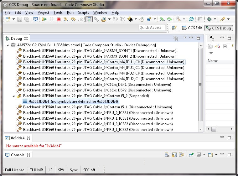
- Connect to C66xx_DSP1
- Connect to C66xx_DSP2
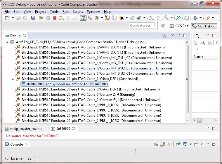
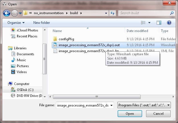
- Load image_processing_evmam572x_dsp1.out to C66xx_DSP1 using JTAG
- Run image_processing_evmam572x_dsp1.out on C66xx_DSP1
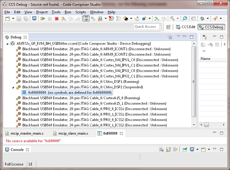
- Load image_processing_evmam572x_dsp2.out to C66xx_DSP2 using JTAG
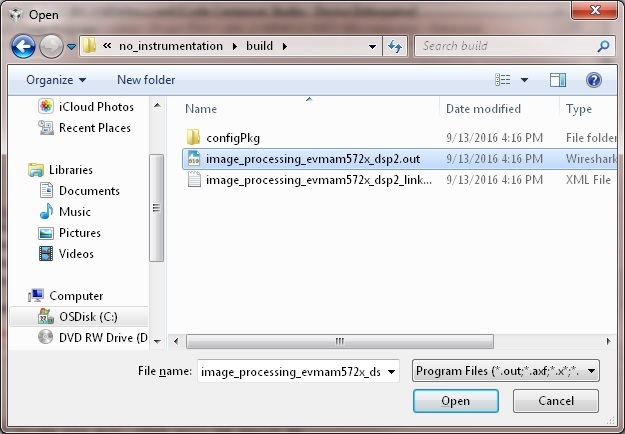
- Run image_processing_evmam572x_dsp2.out on C66xx_DSP2
- Loaded image_processing_evmam572x_host.out to CortexA15_0
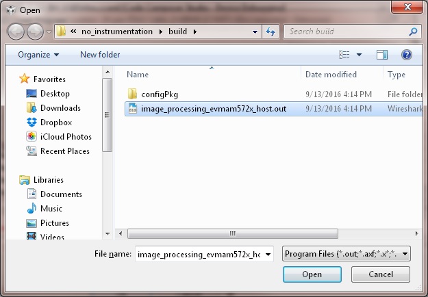
- Run image_processing_evmc6678l_master.out on CortexA15_0
- The HOST will display the IP address on CCS CIO
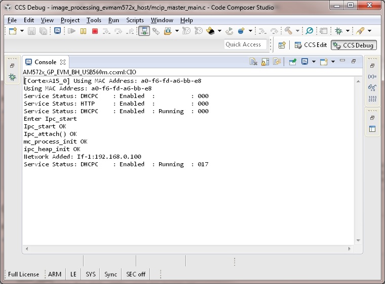
- Users can use internet browser to access this IP address
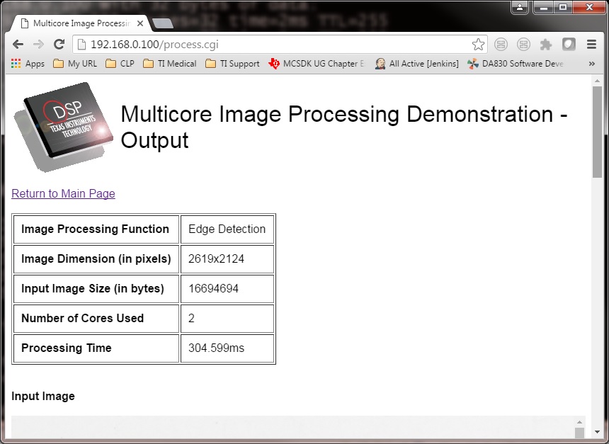
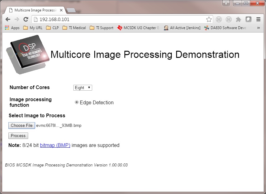
- The Image Processing Demo page will be displayed
- Provide values for the “Number of Cores” and “Select Image to Process” fields
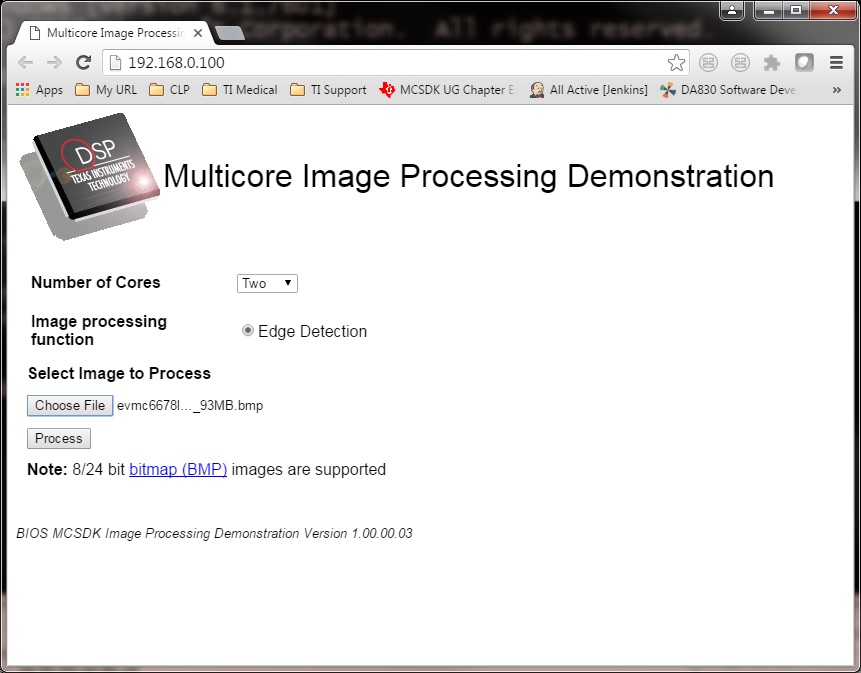
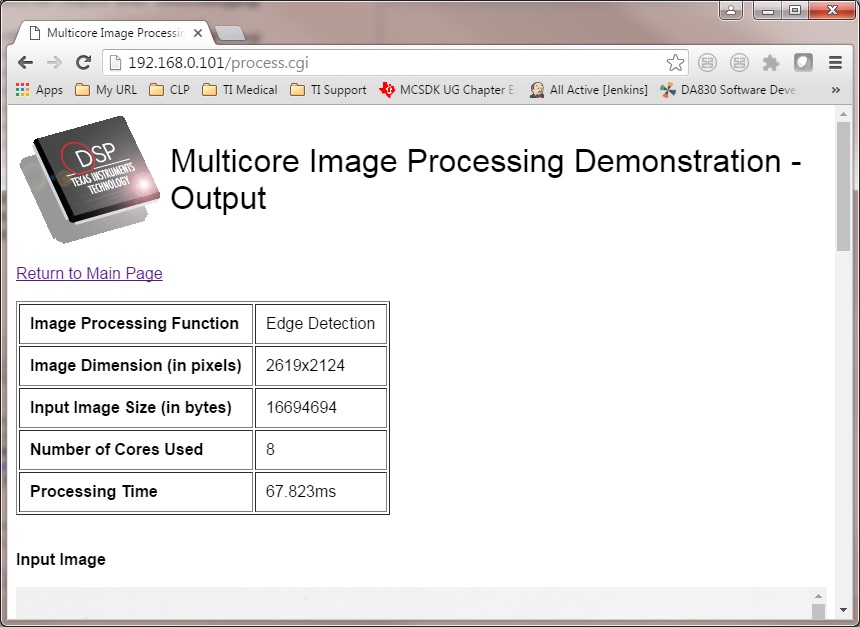
The HOST will read the image via NDK, partition it according to the number of cores, send the messages to DSP cores (Slaves) via IPC MessageQ. The DSP cores will start processing the partitioned images concurrently. The resulting output image will be stored in DDR and the HOST will be notified by DSP cores via IPC MessageQ. Subsequently, the HOST will write the input and output images to the Image Processing Demo page using NDK.
9.1.3.4.2. AM572x GP EVM (Using SBL)
The SBL is used to load the program from SD card and run on ARM-A15 (HOST), C66x Core 1 (DSP1) and C66x Core 2 (DSP2) by following the steps below:
- Copy “app” and “MLO” from processor_sdk_rtos_am57xx_3_0x_00_0x\prebuilt-sdcards\evmAM572x\sd_card_files on Windows or processor_sdk_rtos_am57xx_3_0x_00_0x/prebuilt-sdcards/evmAM572x/sd_card_files on Linux to the root directory of a formatted micro SD card
- Plug in the micro SD card into uSD slot on AM572x GP EVM
- Connect “Serial Debug” on AM572x GP EVM to a PC USB port via a “Serial to USB” cable
- Launch a terminal emulator like Tera Term and open the local COM port corresponding to the “Serial Debug” (Set it to 115200 bps, 8 bit, none parity, one bit stop, no flow control)
- Plug power adapter (12V) into the AM572x GP EVM (DC-In) and power on the EVM
- There the IP address will be displayed on the “Serial Debug”
- Users can use internet browser to access this IP address
- The Image Processing Demo page will be displayed
- Provide values for the “Number of Cores” and “Select Image to Process” fields
The HOST will read the image via NDK, partition it according to the number of cores, send the messages to DSP cores (Slaves) via IPC MessageQ. The DSP cores will start processing the partitioned images concurrently. The resulting output image will be stored in DDR and the HOST will be notified by DSP cores via IPC MessageQ. Subsequently, the HOST will write the input and output images to the Image Processing Demo page using NDK.
9.1.3.4.3. C6678 EVM or C6657 EVM
CCS is used to load the program and Core 0 will be configured as the host. The following steps show C667x but a similar process applies for C665x.
- Launch CCS and connect to C6678 EVM using proper target configuration
- Connect to C66x Core 0 (Host)
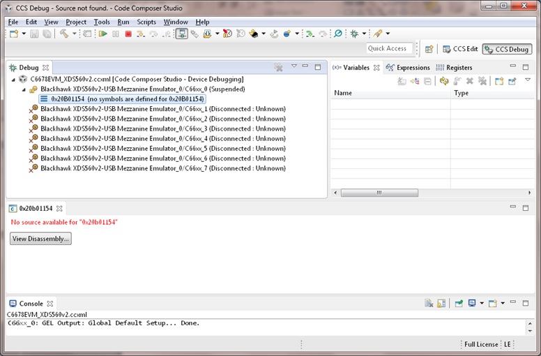
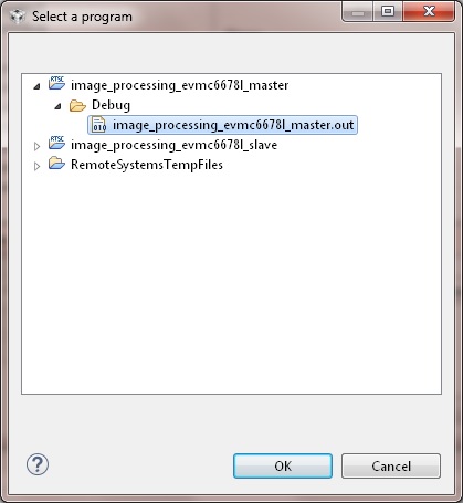
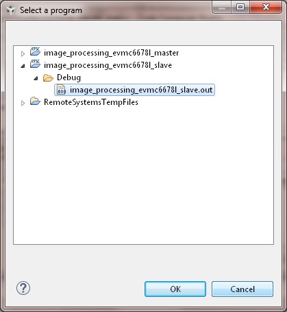
- Loaded image_processing_evmc6678l_master.out to C66x Core 0
- Run image_processing_evmc6678l_master.out on C66xx_0
- Group C66x Core 1-N into a group (Group 1, Slave)
- Connect to Group 1
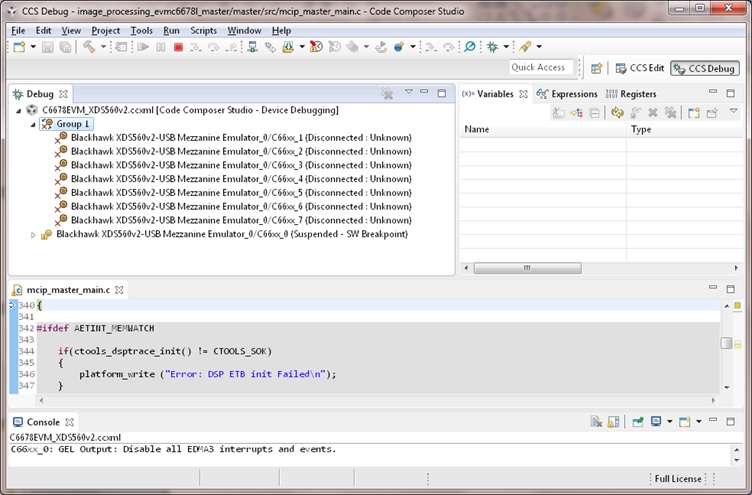
- Load image_processing_evmc6678l_slave.out to Group 1 using JTAG
- Run image_processing_evmc6678l_slave.out on Group 1
- The HOST will display the IP address on CCS CIO
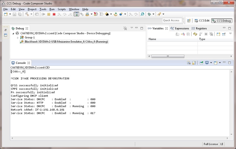
- Users can use internet browser to access this IP address
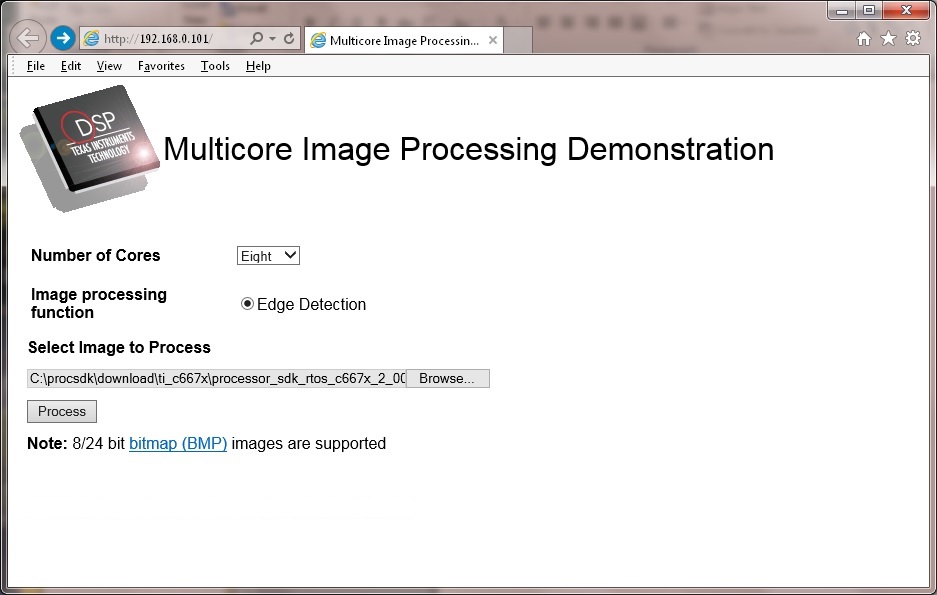
- The Image Processing Demo page will be displayed
- Provide values for the “Number of Cores” and “Select Image to Process” fields
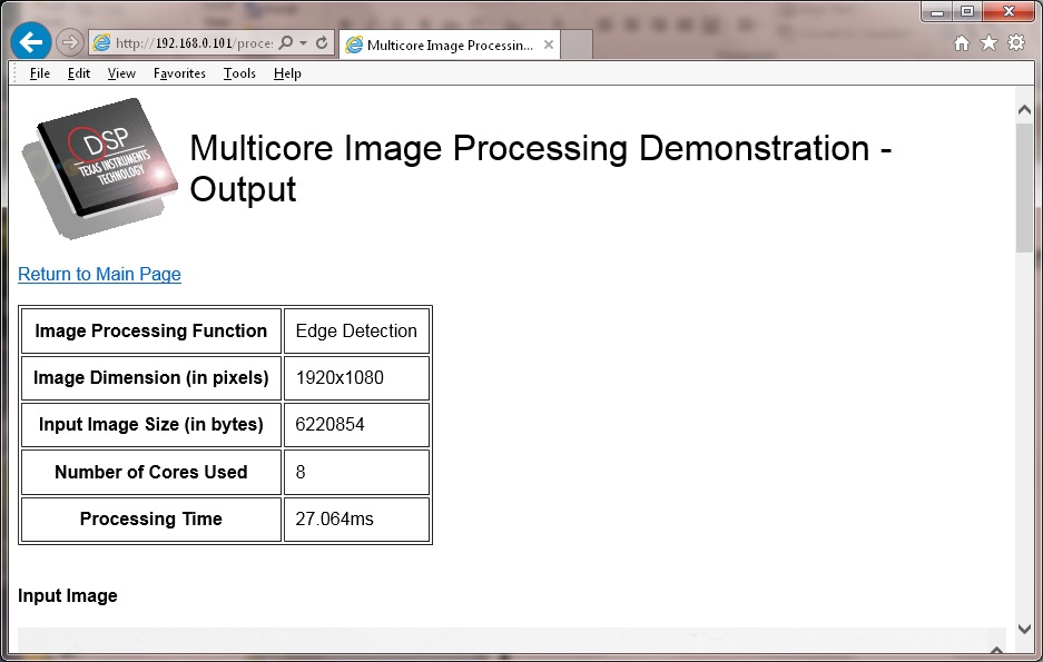
The HOST will read the image via NDK, partition it according to the number of cores, send the messages to DSP cores (Slaves) via IPC MessageQ. The DSP cores will start processing the partitioned images concurrently. The resulting output image will be stored in DDR and the HOST will be notified by DSP cores via IPC MessageQ. Subsequently, the HOST will write the input and output images to the Image Processing Demo page using NDK.
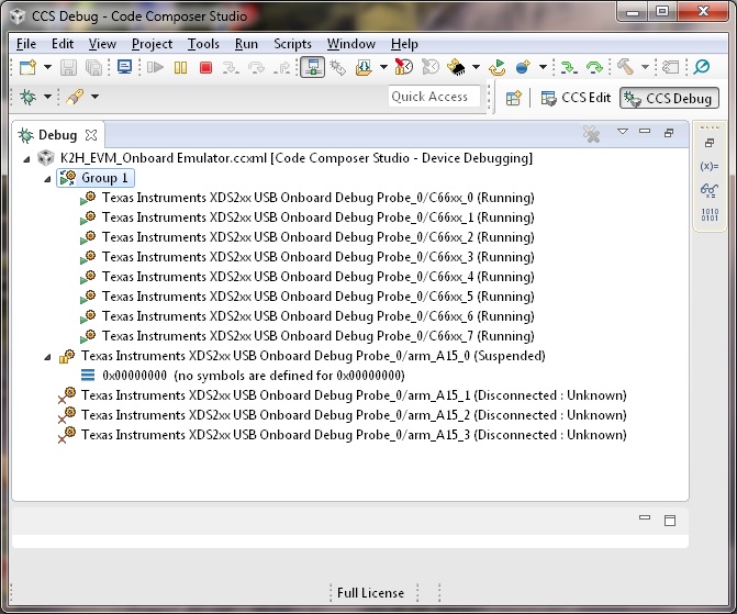
9.1.3.4.4. K2H EVM
CCS is used to load the program and arm_A15_0 will be configured as the master and C66xx_0 - C66xx_7 will be configured as slaves.
- Launch CCS and connect to K2H EVM using proper target configuration
- Connect to arm_A15_0 (Host)
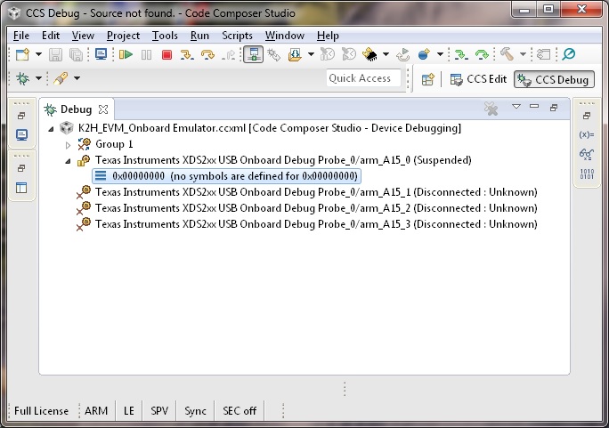
- Group C66xx_0 to C66xx_7 into a group (Group 1, Slaves)
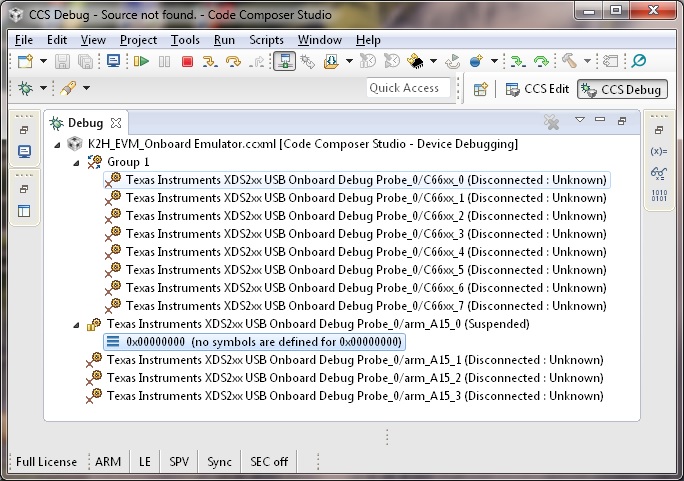
- Connect to Group 1
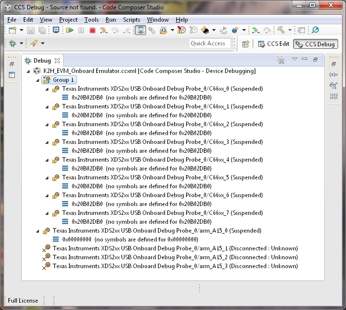
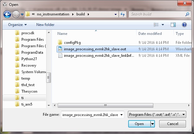
- Load image_processing_evmk2hk_slave.out to Group 1 using JTAG
- Run image_processing_evmk2hk_slave.out on Group 1
- Loaded image_processing_evmk2hk_master_arm.out to arm_A15_0
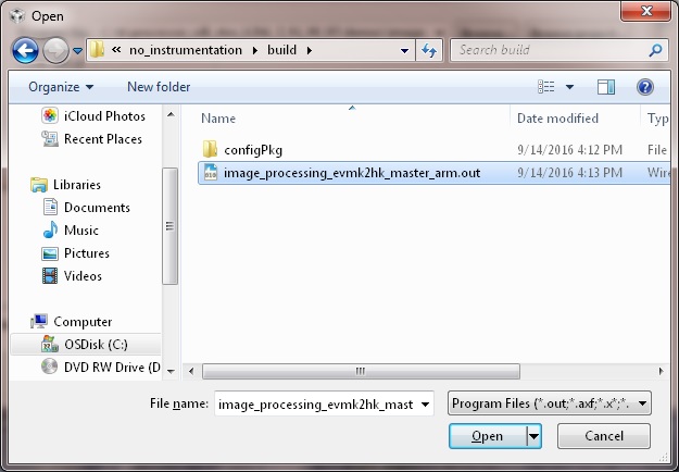
- Run image_processing_evmk2hk_master_arm.out on arm_A15_0
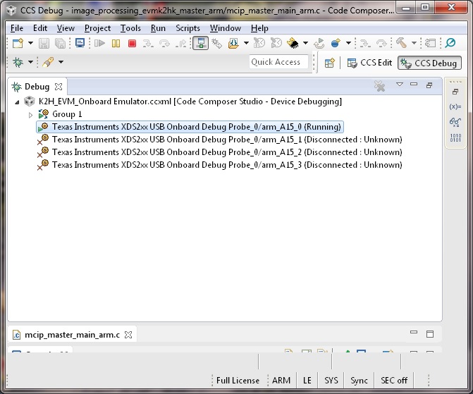
- The HOST will display the IP address on CCS CIO
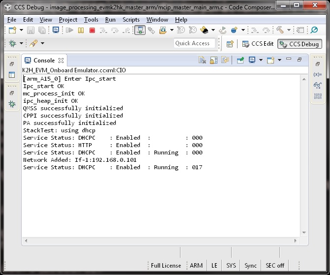
- Users can use internet browser to access this IP address
- The Image Processing Demo page will be displayed
- Provide values for the “Number of Cores” and “Select Image to Process” fields
The HOST will read the image via NDK, partition it according to the number of cores, send the messages to DSP cores (Slaves) via IPC MessageQ. The DSP cores will start processing the partitioned images concurrently. The resulting output image will be stored in DDR and the HOST will be notified by DSP cores via IPC MessageQ. Subsequently, the HOST will write the input and output images to the Image Processing Demo page using NDK.
9.2. POSIX-SMP Demo
9.2.1. Introduction
This page describes the SMP/Posix demo provided in the Processor-SDK for RTOS and Linux. This demo uses Posix APIs together with a simple benchmark (Dhrystone) to automatically calculate the effective throughput of all the cores in each SMP cluster. SMP mode is only supported on Coretex-A15 cores.
This demo runs on:
- AM572x (A15, C66, M4)
- AM437x (A9)
- AM335x (A8)
- K2H (A15, C66)
- K2E (A15, C66)
- K2G (A15, C66)
- K2L (A15, C66)
- C6678 (C66)
- C6657 (C66)
The sections below provide details of the application as well as build and run instructions.
9.2.2. Requirements
The following materials are required to run this demonstration:
Hardware
- TI EVM (see list above)
- Serial UART cable (provided in EVM kit)
Software
- Processor-SDK RTOS
- Code Composer Studio
9.2.3. Software Design
The demo is based on Dhrystone 2.1 from link.
The purpose of the demo is two-fold. First, it is to show easy scaling of throughput across cores in a SMP cluster when running TI-RTOS. Second, it shows easy portability of Posix threads between TI-RTOS and Linux.
The overall requirement is discover all parameters automatically without user input, and to minimize the amount of code that must be customized between TI-RTOS and Linux. This demonstrates that the same Posix threads as well as their setup/control code can be run on either TI-RTOS or Linux with minimal effort.
In order to accomplish this, several major modifications were made to Dhrystone in order to “threadify” it. Some of these changes slightly affect the results compared to an unmodified version. Thus this modified version should be run on all processors where comparisons will be drawn.
- Removal of most printf() during normal operation. Original code dumped all final values for the user to verify. Changed to programmatic verification. Only printf() for actual results (DMIPS and Dhrystones) preserved.
- Removal of all global variables. They are accessed through an “inst” pointer instead.
- Adaptive discovery of iteration count. Original code used a #define. This version doubles iteration count until execution time is about 10M timer ticks.
- Adaptive discovery of number of cores in SMP cluster. Original code didn’t use threads. This version doubled number of threads until cumulative DMIPS flattens out.
POSIX barriers are used inside the timed portion of the code. This is not to time the performance of the barrier, but is instead used to time how long all threads together take to complete. It is assumed the execution times of the threads (> 0.1 second) are orders of magnitude more than the barrier, so the barrier’s effect on results is negligible.
Processor SDK uses makefiles for TI-RTOS and Yocto recipes for Linux for the supported EVMs. The makefile can also be used to compile native builds for Linux (both for EVMs and x86).
For more information on TI-RTOS Posix, see POSIX Support.
9.2.4. How to Run the Demo
The processor SDK includes pre-built binaries which may be loaded and run using the SBL with UART or using CCS with UART or ROV (UART display for newer versions and ROV for older versions). To run using UART, hook up to the board using UART and run the .out file.
To run using CCS, use the following steps. Each binary has an associated \*.rov.xs file located in the same directory–enabling the CCS ROV tool. Newer versions will display directly to the UART console and any steps involving ROV may be skipped.
<SDK_INSTALL_PATH>/processor_sdk_rtos_<platform>_2_00_xx_xx/demos/posix-smp/bin/<platform>/<core>/debug/dhry.out
<SDK_INSTALL_PATH>/processor_sdk_rtos_<platform>_2_00_xx_xx/demos/posix-smp/bin/<platform>/<core>/debug/dhry_pa15fg.rov.xs
For all platforms and core types, the basic procedure for running the demo will be the same:
- Using CCS, launch the target configuration for the EVM CCS-Target Configurations. Please ensure that the target configuration will load the appropriate CCS gel files found in the emupak. Make sure all Coretex-A15 cores in the SMP cluster have an appropriate CCS gel file.
- The default ccxml file only loads a gel on connect for some of the cores. Modify the ccxml file to load the gel for all the corresponding cores.
- In the CCS debug view, group and then connect to all cores of device that you wish to test on (i.e. - all of the clustered A15 cores).
- For each, core load the dhry.out file. The principle core should halt at main while the SMP linked cores will begin auto-running upon load.
- Once all cores have been loaded, run all the cores.
- The output will be sent to the UART console in real time.
- The demo should not take more than a few minutes to run. You must manually halt the cores to end the demo.
If using Processor-SDK 3.0 or later,
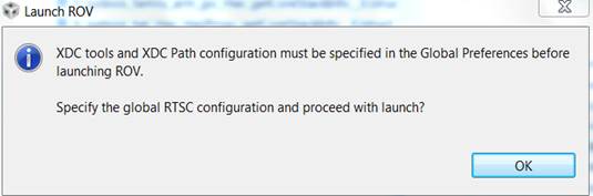
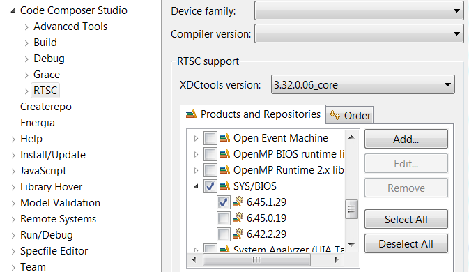
- Open the ROV window (Tools > RTOS Object View (ROV)) and view the SysMin module to inspect the output of the demo. If you see the below message, please specify the XDC and SYSBIOS versions:
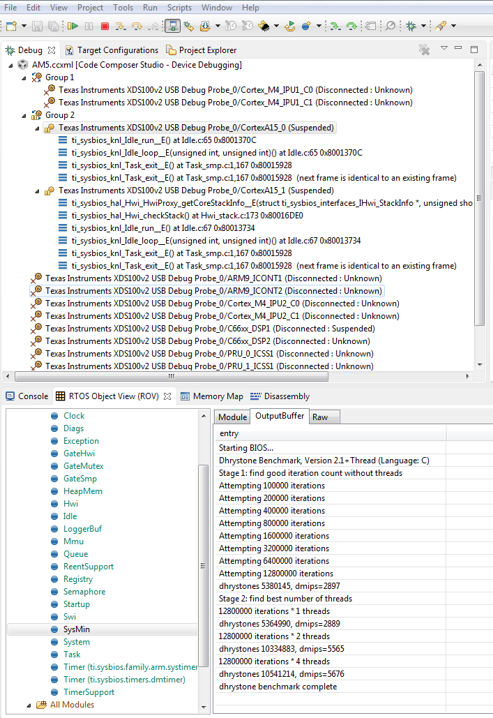
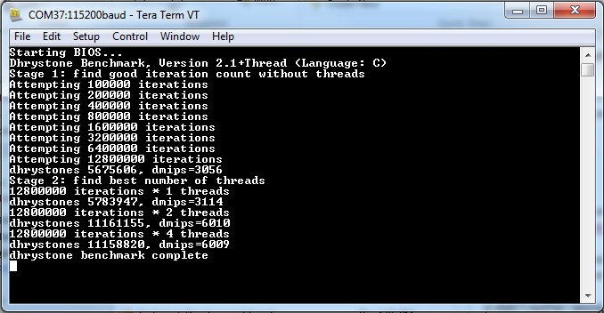
The output buffer shown in the ROV contains the different stages of the demo’s progression:
- The demo finds an appropriate number of iterations for the device.
- The demo begins to add threads.
- The demo concludes when adding additional threads does not further increase the DMIPS.
The output takes the form of: “xxxxxxx iterations *n threads; dhrystones xxxxxxxx, dmips = xxxx”. In the screenshot above, moving from two threads to four threads does not appreciably improve the DMIPS, so the demo completes. This behavior is expected because the demo is only running on two cores in this example.
Note
- A15 cores may usually be connected to directly; on the AM572x, the M4 IPUs must first be initialized by the gel scripts (Scripts > AM572x MULTICORE initialization > IPUxSSClkEnable_API)
- If the K2 demo will not run, try updating to the latest emupack by doing “Help/Check For Updates” and selecting “Keystone2 device support” update (only). There are additional instructions for configuring groups, etc. at SMP Debug.
- If the primary core of an SMP group will not allow running after loading the demo, try pausing the linked cores and then running all the cores in a group
- For TI-RTOS documentation for enabling SMP, refer to SMP/BIOS. The POSIX demo in the Processor SDK RTOS packages with C66x does not support SMP. This is a POSIX pthread demo intended to run Dhrystone on one C66x core without SMP.
- Some of the DMIPS values may not be accurate, but the values will increase proportionally with the number of cores
9.2.5. How to Build the Demo
9.2.5.1. Processor-SDK RTOS
To build the project manually, first navigate to the top level makefile:
<SDK_INSTALL_PATH>/processor_sdk_rtos_<platform>_2_00_xx_xx/demos/posix-smp/makefile
Edit the makefile to include the paths to BIOS, XDC, PDK packages, and the toolchains for the cores being used.
#DEPOT = <ROOT_INSTALL_PATH>
#### BIOS-side dependencies ####
#BIOS_INSTALL_PATH ?= $(DEPOT)\bios_n_nn_nn_nn
#XDC_INSTALL_PATH ?= $(DEPOT)\xdctools_n_nn_nn_nn_core
#### BIOS-side toolchains ####
#TOOLCHAIN_PATH_A15 ?= $(DEPOT)\ccsv6\tools\compiler\gcc-arm-none-eabi-n_n-xxxxqn
#TOOLCHAIN_PATH_M4 ?= $(DEPOT)\ccsv6\tools\compiler\ti-cgt-arm_x.x.x
Navigate to the demo directory and run “make”. The steps to run the demo will be the same.
9.3. Audio Benchmark Starterkit
9.3.1. Introduction
The Audio Benchmark Starterkit is intended to provide an easy and quick way to benchmark key audio functions on C66x and C674x DSP devices. This package is intended for users who are new to the TI DSP development environment and provides an easy path to compare core audio benchmarks to other implementations. For the purposes of benchmarking we have selected the following signal processing functions
- Complex Fast Fourier transform (FFT)
- Real Block FIR filters with 128 samples, 16 coefficients
- Cascaded Biquad (2 channels, 3 stages) IIR filter for 128 Samples
The package is also a great way to get familiar with benchmarking functions on TI DSP with or without TI`s Code Composer Studio environment. It also intends to provide guidance on the compiler options and code/data memory placement that allows developers to obtain optimal performance on TI DSP architecture. The package also demonstrates use of signal processing functions from TI C6000 DSPLIB which contains several kernels optimized for TI DSP architectures.
9.3.2. Software Features
- Benchmark applications for core signal processing functions
- Makefile and CCS Project scripts to build applications
- SD card bootable binaries [Supported on SOCs that support SD boot]
9.3.3. Directory Structure
The audio benchmark starterkit is located in the Processor SDK RTOS release under the directory path
<SDK_INSTALL_PATH>\processor_sdk_rtos_<soc>_x_xx_xx_xx\demos\audio-benchmark-starterkit
Detailed description of the directory structure is given below: .. Image:: ../images/Audben_dirStructure.png
- prebuilt-binaries - directory contains prebuilt out files to run the benchmarks.
- bootimages - SD card boot files to run the benchmarks using SD boot.
- docs - directory contains ReadMe, Quick start guide and the software manifest for the package.
- scripts - directory contains .txt script files that is used by BenchmarkProjectCreate script to create CCS projects
- src - common - Contains linker command file and logging functions used by all benchmark tests. - singlePrecision_FFT - Source files for benchmark app for FFT - singlePrecision_FIR - Source files for benchmark app for FIR - singlePrecision_IIR - Source files for benchmark app for IIR
9.3.4. Software Dependencies
Note
For correct version of Code Composer Studio to download, please refer to the `Release Notes <https://processors.wiki.ti.com/index.php/Processor_SDK_RTOS_Release_Notes>`__ corresponding to the Processor SDK RTOS version that you have installed
9.3.5. Supported Hardware
Platforms supported in Processor SDK RTOS 3.3 and later
Platforms planned in Processor SDK RTOS 4.0
9.3.6. QuickStart with How-To-Video
For an easy and visual experience to build and run the benchmark tests, we have created a short How to video that demonstrates how the Benchmark Starterkit can be built and run on C66x DSP on the K2G EVM which you can check out from the link provided below:
9.3.7. How to Build the Benchmarks
The benchmark starterkit is designed to build with makefiles as well as with Code Composer Studio (CCS) IDE Environment. Both the approaches requires developers to setup the Processor SDK RTOS development environment. Developers can use either approach based on their familiarity with the chosen build environment. Let us take a closer look at both approaches.
9.3.7.1. Using Makefile
Step1 : Setup Processor SDK RTOS build Environment.
Developers are required to setup the Processor SDK RTOS build environment as described in Processor SDK RTOS Setup environment
- set SDK_INSTALL_PATH = C:\ti\<Install directory>
- setupenv.bat
Note
If developers install CCS or Processor SDK RTOS under Custom path then they need to refer to the setup instructions described under Setup environment when installing to a custom path
Step2 : Invoke Make from root directory
The make file in the root director of the audio-starterkit can be used to build the entire package. To build the benchmark examples:
- cd <PROC_SDK_INSTALL_PATH>/demos/audio-benchmark-starterkit
- make all
Note
The build picks up the SOC information from the SDK setup. Also, in the make environment the benchmark application is built to send benchmark logs to UART console so that there is no dependency on the CCS IDE environment
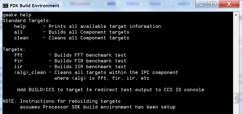
For Other supported options, please type
For Windows:
gmake help
For Linux :
make help
All available options are provided below:
9.3.7.2. Using CCS Projects
The audio benchmark starterkit does not provide pre-canned CCS Projects as it is difficult to set up projects to be portable across various developer build environments. To create CCS Projects with the benchmarks, developers are required to run the BenchmarkProjectCreate script provided in the root directory of the starterkit.
Step1 : Setup Processor SDK RTOS build Environment.
- set SDK_INSTALL_PATH = C:\ti\<Install directory>
- set TOOLS_INSTALL_PATH = C:\ti\<CCS Install directory>
- setupenv.bat
Note
CCS by default is installed in the path C:\ti\ccsv7 so TOOLS_INSTALL_PATH=C:\ti
Developers are required to setup the Processor SDK RTOS build environment as described in Processor SDK RTOS Setup environment
If developers install CCS or Processor SDK RTOS under a Custom path then they need to refer to the setup instructions described under Setup environment when installing to a custom path
Step 2: Run BenchmarkProjectCreate script to generate CCS Projects
To generate the CCS Projects
- cd $PROC_SDK_INSTALL_PATH/demos/audio-benchmark-starterkit
- BenchmarkProjectCreate [Options]
The Project create script can be run using the following syntax
BenchmarkProjectCreate.bat <soc> <board> <all>
Description of arguments:
- soc - K2G (Default) / K2H/ K2E/ C6678/ C6657/ AM572X/ AM571x/ OMAPL138
- board - all (Default) / <SOC supported EVMs>
- module - all / (FFT / FIR / IIR)
Example:
 a) BenchmarkProjectCreate.bat
             - Creates all module projects for the K2G soc for evmK2G platform
 b) BenchmarkProjectCreate.bat AM572x
             - Creates all module projects for AM572x soc for evmAM572x and idkAM572x platform
 c) BenchmarkProjectCreate.bat C6657 evmC6657
             - Creates all modules for C6657 DSP for evmC6657 platform
 d) BenchmarkProjectCreate.bat K2H evmK2H FFT
             - Creates FFT module project for K2H soc for evmK2H
Note
Known issue with Processor SDK RTOS 3.3 The BenchmarkProjectCreate script uses text files .txt from scripts folder to generate the CCS projects. The name for the demo folder was updated from “audio-benchmark-kit” to “audio-benchmark-starterkit”. This will require CCS users to update the name in the .txt file before generating the scripts.
For Example if you are using K2G platform locate file Benchmark_FFT_evmK2G_c66ExampleProject.txt, Benchmark_FIR_evmK2G_c66ExampleProject.txt and Benchmark_IIR_evmK2G_c66ExampleProject.txt and update the demo name in the text files from “audio-benchmark-kit” to “audio-benchmark-starterkit”
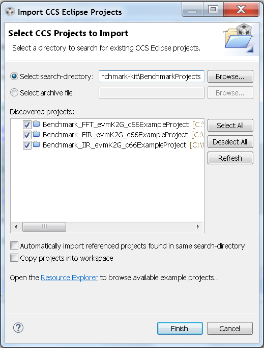
Step 3: Import Generated CCS Projects in CCS Workspace
Launch CCS and Import the CCS Project using the Project->Import Existing CCS Project and browse to the audio-benchmark-starterkit folder
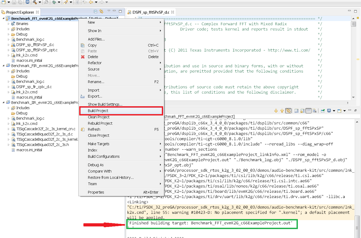
Step 4: Build Imported CCS Benchmark Projects
Right click on the Benchmark Project File and Build the project as shown below:
9.3.8. How to Run the Benchmarks
The benchmark examples can be run by loading the built out files with an emulator using the CCS Debug functionality or the examples can be run on the DSP by creating SD card bootable images using out files. Let us take a look at both these approaches.
9.3.8.1. Using CCS
Step 1: Connect Emulator and UART to Hardware
- Refer to the Hardware Setup guide and connect the onboard or external emulator to the Hardware and Host machine with CCS installed.
- Connect the UART cable from the EVM to the Host machine and configure
the Serial console with following settings:
- Baud Rate: 115200
- Data Bits: 8
- Parity: None
- Flow Control: Off
Step 2: Create Target configuration and connect to the DSP
To connect to the SOC, developers need to create a Target configuration by following the procedure described in wiki Create_Target_Configuration_File_for_EVM
Instructions specific to supported EVMs:
Note
Please refer to Hardware User Guide corresponding to each supported EVM so setup the boot switches to No boot if available
Step 3: Loading and Running Benchmark application on the DSP
- Load the out file using Run -> Load -> Load Program and browse to the output binary.
- After loading the out file, run the benchmark app by Pressing F8 or Run -> Resume
9.3.8.2. Using SD card (Supported only on AM57xx and K2G)
Step 1: Run Create SD script to generate SD bootable binaries
The root directory in the audio-benchmark-starterkit contains a create-sd.bat file that will convert the .out files installed int the bin folder into SD bootable images which will be installed in the path bin/sd_card_files/<EVM>
The syntax to run the create-sd script is as follows:
create-sd.bat <EVM>
EVM : refers to evaluation platfom on which the binaries are meant to be run
Eg: create-sd evmK2G - Creates SD bootable images for K2G EVM.
Step 2 : Format and copy the SD card binaries to the SD card
Create an SD card using the procedure described in Creating SD card in Windows and Create SD card in Linux
Copy the “MLO” and “Singleprecision_<Module>_app” to the boot partition on the SD card.
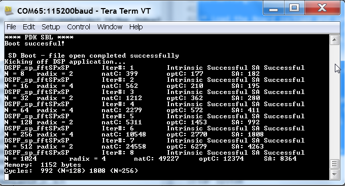
Step 3: Boot the Benchmark app by configuring SD boot on the EVM
- Configure the boot switches on the evaluation hardware to SD boot.
- Insert the SD card in the microSD or SD card slot on the board.
- Connect the UART on the hardware to the Host and configure the host to Baud Rate= 115200, Data Bits= 8 , Parity= None, Flow Control= Off
- Power on the EVM to view the output on the Serial console on the host
9.3.9. Benchmark App output on UART console
9.3.9.1. Benchmark Starterkit Implementation
Signal Processing functions used in Starterkit
Single Precision FFT: DSPF_sp_fftSPxSP (Mixed Radix Forward FFT )
The audio benchmark kit uses the FFT implementation(DSPF_sp_fftSPxSP) from the TI DSP Library. The DSPF_sp_fftSPxSP kernel calculates the discrete Fourier transform of complex input array ptr_x using a mixed radix FFT algorithm. The result is stored in complex output array ptr_y in normal order. Each complex array contains real and imaginary values at even and odd indices, respectively. DSPF_sp_fftSPxSP kernel is implemented in assembly to maximize performance, but a natural C implementation is also provided. The demonstration app for this kernel includes the required bit reversal coefficients, brev, and additional code to calculate the twiddle factor coefficients, ptr_w.
Note
- For implementation details of this FFT computation refer to documentation provided in Additional resources
- For Real input sequences, efficient FFT Implementation is described here Efficient_FFT_Computation_of_Real_Input
Single Precision FIR: DSPF_sp_fir_cplx (Complex FIR Filter)
The audio benchmark kit uses the FFT implementation(DSPF_sp_fftSPxSP) from the TI DSP Library. The DSPF_sp_fir_cplx kernel performs complex FIR filtering on complex input array x with complex coefficient array h. The result is stored in complex output array y. For each complex array, real and imaginary elements are respectively stored at even and odd index locations.
The API reference and the implementation details can found in the TI DSPLIB documentation included in the Processor SDK.
Single Precision IIR : tisigCascadeBiquadSP_2c_3s_kernel (Cascade Biquad Filter for Multichannel input)
The Cascade biquad filtering function in the audio benchmark starterkit is an improved biquad infinite impulse response filter Patent US20160112033 Pending. The new filter structure modifies the feedback path in the filter, resulting in a significant reduction in execution cycles. One of the most-used digital filter forms is the biquad. A biquad is a second order (two poles and two zeros) Infinite Impulse Response (IIR) filter. It is high enough order to be useful on its own, and because of the coefficient sensitivities in higher order filters the biquad is often used as the basic building block for more complex filters. For instance, a biquad low pass filter has a cutoff slope of 12 dB/octave, useful for tone controls; if a 24 dB/octave filter is needed, you can cascade two biquads and it will have less coefficient sensitivity problems than a single fourth-order design.
For implementation details please check the USTO link
API reference:
int tisigCascadeBiquad32f_2c_3skernel(CascadeBiquad_FilParam *pParam)
where CascadeBiquad_FilParam is defined as
CascadeBiquad_FilParam {
     float *restrict pin1;    // Input Data Channel 1
     float *restrict pin2;    // Input Data Channel 2
     float  *restrict pOut1;  // Output Data Channel 1
     float  *restrict pOut2;  // Output Data Channel 1
     float  *restrict pCoef;  // Filter Coefficients a, b for 3 stages
     float  *restrict pVar0;  // Filter Variables d0, d1 for 3 stages channel 0
     float  *restrict pVar1;  // Filter Variables d0, d1 for 3 stages channel 1
     int      sampleCount;    // Number of samples
}  CascadeBiquad_FilParam;
9.3.10. Memory placement of Instruction and Data
The best performance of the DSP can be obtained by placing all the data and instructions in L2 SRAM. Please refer to the linker command files include in the src/common folder to see how the instructions and data can be place in DSP internal L2 memory.
Note
In application use cases where audio data needs to be place in onchip shared memory (OCMC or MSMC) and DDR memory, we recommend that users move data from external memory to L2 for processing using EDMA or enable DSP cache using CSL to optimize performance.
9.3.11. Compiler Optimization Flags
All the projects in the Audio Benchmark starterkit are built using C6000 compiler with -o3 optimization that allows the source code to be compiled with highest compiler optimization settings. User can refer to the compiler Build settings in the Makefiles or go to Build Settings in CCS Project settings to modify the compiler options.
Note
For more Details on recommended C6000 Compiler options refer C6000_Compiler:_Recommended_Compiler_Options
- C6000 compiler documentation: C6000 Compiler v8.x User Guide
9.3.12. SOC Integration and Optimization
9.3.12.1. Configuring device clocks
Every SOC with TI DSP requires users to enable the DSP clocks by setting up the PLL and or enabling the DSP through Power Sleep Controller or Power and Control (PRCM) module. The way the clocks are set up differs depending on the environment setup
- Development environment with emulator:In this case the SOC clocks are setup using GEL files which are added to the target configuration file. For audio benchmark starterkit, this done using GEL files setup explained in the Hardware Setup section
- Application Boot from boot mediaIf you are booting application from a boot media like SD/MMC or flash device, the ROM bootloader or a secondary level bootloader performs the clock configuration. For audio starterkit, this initialization is done using board library which is linked to the secondary bootloader and the benchmark tests.
Note
If the clocks are not configured the DSP will run at speed of the input clock rather than at the device speed grade. Hence if the clocks are not configured correctly the benchmarks will run much slower than anticipated but the cycle count will show the same.
9.3.13. Benchmarking using DSP TSCH/TSCL registers
For C66x+ and C674x members of the C6000 family, there is a pair of registers, TSCL and TSCH, which together provide a 64-bit clock value. You can create your own clock function to take advantage of these registers. Simply add this function to your program and it will override the clock function from the library.
The Bench mark test application, use the following functions to capture cycle count using the TSCH and TSCL regsiters.
/* ---------------------------------------------------------------- */
/* Initialize timer for clock */
TSCL= 0,TSCH=0;
/* Compute the overhead of calling _itoll(TSCH, TSCL) twice to get timing info */
/* ---------------------------------------------------------------- */
t_start = _itoll(TSCH, TSCL);
t_stop = _itoll(TSCH, TSCL);
t_overhead = t_stop - t_start;
t_start = _itoll(TSCH, TSCL);
<Algorithm to be bechmarked>
t_stop = _itoll(TSCH, TSCL);
t_measured = (t_stop - t_start) - t_overhead;
9.3.14. Benchmark logging
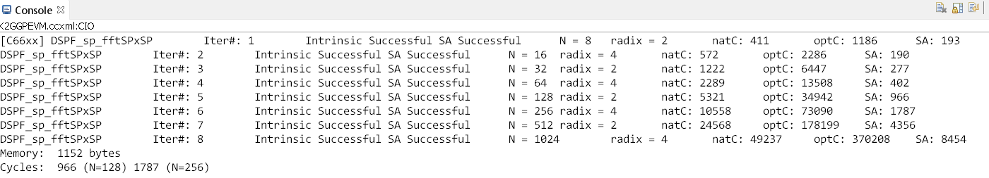
The Audio benchmarks demonstrates two ways to log benchmark numbers. One approach that can be used when code is loaded and run from Code composer studio is to use standard printf messages from the standard IO RTS libraries and the other approach is to use UART based logging that can send the benchmark logs to serial console on the host at the baud rate of 115.2 kbps.
All the benchmark test application include a file Benchmark_log.h and Benchmark_log.c, that are used to log messages based on the definition of macro IO_CONSOLE. If IO_CONSOLE is defined the output will be directed to CCS console. If it is not defined, the logs are sent to the UART console.
Makefiles and scripts that build binaries to boot from SD card will not have IO_CONSOLE defined hence the benchmark logs will be directed to the UART serial console. In the CCS projects, we define the IO_CONSOLE macro so that the output can be observed on the CCS console.
9.3.15. Cache configuration for Code/data sections in SRAM/DDR
The best performance of the DSP can be obtained by placing all the data and instructions in L2 SRAM. If developer application use cases places audio data in onchip shared memory (OCMC or MSMC) and DDR memory then the user will need to enable L1 and L2 cache using CSL API.
To enable and utilize cache in the application, please refer to the csl_cacheAux.h file in the pdk_<soc>_x_x_x/packages/ti/csl folder in the SDK and link the CSL library for the soc into the application code.
9.3.16. Benchmark results
| AlgorithmDSP Architecture | C66x DSP | C674x DSP |
|---|---|---|
| Single Precision FFT (256 samples) | 1808 cycles | 2314 cycles |
| Single Precision FIR (128 samples, 16 coefficients) | 2652 cycles | 4465 cycles |
| Single Precision IIR (1k samples from 2 channel with 3 stage cascade biquad) | 8258 cycles | 12381 cycles |
Note
- All code and data for the benchmark tests is placed in L2 Memory.
- C6000 compiler version used was CGTools v8.1.3
- Bench marks were obtained from C66x DSP on K2G and C674x DSP on OMAPL138 LCDK
- FFT and FIR benchmarks were obtained using the DSPLIB functions.
9.3.17. Support
For questions, feature requests and bug reports, please use the TI E2E Forums provided below:
- For C66x and K2x devices : Multicore DSP Forums
- For OMAPL and C674x devices : Single core DSP Forums
- For AM57xx devices: Sitara Forums
9.3.18. Additional resources
White papers:
- Introduction to TMS320C6000 DSP Optimization
- TI DSP Benchmarking
- Optimizing Loops on C66x
- TI’s new TMS320C66x fixed and floating-point DSP core conquers the ‘Need for Speed’
- Efficient fixed- and floating-point code execution on the TMS320C674x core delivers faster code development and reduces system cost with improved performance
9.4. Audio Pre-Processing Demo
9.4.1. Introduction
This page describes the audio pre-processing for speech recognition framework provided in the Processor-SDK for RTOS. This demo illustrates the integration of Beamforming (BF), Adaptive Spectral Noise Reduction (ASNR), Multiple Source Selection (MSS) and Dynamic Range Compression (DRC) components and provides a framework for application development.
The key functions in this use case include:
- Read 7 canned audio input files from hard drive into buffers in DDR using GEL function
- Generate 12 virtual mics using BF (Beamforming) (30° apart)
- Apply ASNR (Adaptive Spectral Noise Reduction) on each virtual mic
- Use MSS (Multiple Source Selection) to select the best virtual mic from the 12 virtual mics
- Do DRC (Dynamic Range Compression) on the best virtual mic
- Display performance data
- Write one processed audio channel from buffer in DDR to hard drive using GEL function
This demo utilizes other Processor SDK features/components:
- SYS/BIOS application utilizing TI-RTOS features for DSP-C66x/C674x core
- UIA for instrumentation logging
The audio components are available in AER and VOLIB packages, which are optimized for C66x cores, so this demo not available for all devices. Currently, the following devices and EVMs are supported:
- AM57x, on the AM572x GP EVM
- K2G, on the K2G EVM. See TIDEP-0088 (https://www.ti.com/tool/TIDEP-0088) for details
- OMAP-L137, on the OMAP-L137 EVM. See TIDEP-0099 (https://www.ti.com/tool/TIDEP-0099) for details
9.4.2. Requirements
The following materials are required to run this demonstration:
Hardware
- TI EVMs (see list above)
- CMB for K2G and OMAP-L137, if using circular microphone
- Blackhawk USB560 JTAG Emulator (BH-USB-560m)
Software
- Processor-SDK RTOS (4.0 or greater)
- Code Composer Studio
- AER 17.0.0.0 (C64P) (https://www.ti.com/tool/telecomlib)
- VOLIB 2.1.0.1(C64P for OMAP-L137, C66 for K2G and AM572x) (https://www.ti.com/tool/telecomlib)
9.4.3. Software Design
9.4.3.1. More about processing algorithms
The application will use AER & VOLIB APIs for its noise reduction processing needs. The following steps are performed for noise reduction:
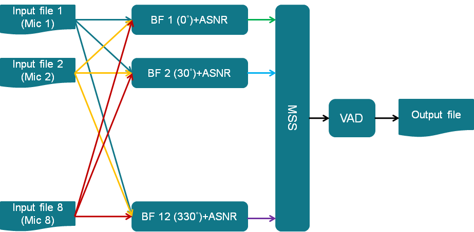
- Use 7 canned audio inputs to generate 12 virtual mics using BF(Beamforming) (30° apart)
- Apply ASNR(Adaptive Spectral Noise Reduction) on each virtual mic
- Use MSS(Multiple Source Selection)to select the best virtual mic from the 12 virtual mics
- Do VAD(Voice Activity Detection) on the best virtual mic
- Write 1 processed audio channel into the buffer in DDR
9.4.3.2. Framework for Audio Pre-processing
The current framework is based on SYS/BIOS. The following are the overall steps:
- The CLK object in SYS/BIOS will be configured to generate a Software Interrupt(SWI) every 10 ms
- The SWI will prepare the audio frame buffer pointers for further processing
- The SWI will also send a semaphore to wake up the main thread
- When woke up, the main thread will perform the BF, ASNR, MSS and DRC
- The main thread will also output the final processing audio frame to the DDR
- After completed the audio frame processing, the main thread will wait on semaphore for next audio frames to come
9.4.4. File Based Demo
9.4.4.1. How to Build the Demo
Note
In order to make the following build procedure to work, AER and VOLIB have to be installed at the same location as the Processor SDK RTOS 4.x.x
9.4.4.1.1. AM572x GP EVM
For Linux:
- Under processor_sdk_rtos_am57xx_4_xx_xx_xx directory, run the following commands:
source ./setupenv.sh
cd demos/audio-preprocessing/file_demo_bios/am572x/build
make clean
make all
the OUT files for DSP1 will be built at
   processor_sdk_rtos_am57xx_4_xx_xx_xx/demos/audio-preprocessing/file_demo_bios/am572x/build
For Windows:
- Under processor_sdk_rtos_am57xx_4_00_xx_xx directory, run the following commands:
setupenv.bat
cd demos\audio-preprocessing\file_demo_bios\am572x\build
gmake clean
gmake all
the OUT files for DSP1 will be built at
   processor_sdk_rtos_am57xx_4_xx_xx_xx\demos\audio-preprocessing\file_demo_bios\am572x\build
9.4.4.1.2. K2G EVM
For Linux:
- Under processor_sdk_rtos_k2g_4_xx_xx_xx directory, run the following commands:
source ./setupenv.sh
cd demos/audio-preprocessing/file_demo_bios/k2g/build
make clean
make all
the OUT files for DSP will be built at
   processor_sdk_rtos_k2g_4_xx_xx_xx/demos/audio-preprocessing/file_demo_bios/k2g/build
For Windows:
- Under processor_sdk_rtos_k2g_4_00_xx_xx directory, run the following commands:
setupenv.bat
cd demos\audio-preprocessing\file_demo_bios\k2g\build
gmake clean
gmake all
the OUT files for DSP will be built at
   processor_sdk_rtos_k2g_4_xx_xx_xx\demos\audio-preprocessing\file_demo_bios\k2g\build
9.4.4.1.3. OMAP-L137 EVM
For Linux:
- Under processor_sdk_rtos_omapl137_4_xx_xx_xx directory, run the following commands:
source ./setupenv.sh
cd demos/audio-preprocessing/file_demo_bios/omapl137/build
make clean
make all
the OUT files for DSP will be built at
   processor_sdk_rtos_omapl137_4_xx_xx_xx/demos/audio-preprocessing/file_demo_bios/omapl137/build
For Windows:
- Under processor_sdk_rtos_omapl137_4_xx_xx_xx directory, run the following commands:
setupenv.bat
cd demos\audio-preprocessing\file_demo_bios\omapl137\build
gmake clean
gmake all
the OUT files for DSP will be built at
   processor_sdk_rtos_omapl137_4_xx_xx_xx\demos\audio-preprocessing\file_demo_bios\omapl137\build
9.4.4.2. How to Run the Demo
The demo along with the audio input files will be loaded onto the target using JTAG. After executing, the output file can be read from target. Play both input and output audio files to compare effect of audio pre-processing.
The following sections provide detailed steps for each EVM.
9.4.4.2.1. AM572x GP EVM
- Follow this link Setup CCS for EVM and Processor-SDK RTOS to get target configuration setup correctly.
- Then in CCS tools –> Gel file to load the modified gel file – audio-preprocessing/file_demo_bios/am572x/files_io_7.gel
- Connect the Blackhawk USB 560M JTAG to P4 on AM572x GP EVM
- Plug power adaptor(12V) into the AM572x GP EVM (Do not press the Power Button(S1) yet)
- Launch the target configuration created in step 1 using “Launch Selected Configuration” from CCS 6.1.3
- Press the Power Button(S1) and “Connect to CortexA15_0” immediately (Due to the EVM will be auto power off in 10 secs)
- Then “Connect to C66xx_DSP1”
- Load the AM572x_bf.out from audio-preprocessing\file_demo_bios\am572x\build
- Execute GEL function Scripts–>Microphone Load Functions–>BFMicLoadAll to load all 7 microphone input files (audio-preprocessing\common\t8\y16L7g3m7090_x.pcm) into external memory buffers
- Run the program (loaded previously) by pressing F8
- The program will print out the statistics and “EOF reached” when the program completes processing
- Execute GEL function Scripts–>Microphone Save Functions–>BFSaveOutput to save the processed audio output from external memory buffer to a file (audio-preprocessingcommont8fileOutput7.bin)
9.4.4.2.2. K2G EVM
- Follow this link Setup CCS for EVM and Processor-SDK RTOS to get target configuration setup correctly.
- Then in CCS tools –> Gel file to load the modified gel file – audio-preprocessing/file_demo_bios/k2g/files_io_7.gel
- Connect to the on board emulator (J1 on K2G EVM) to your PC USB
- Plug power adaptor(12V) into the K2G EVM and power on the EVM
- Launch the target configuration created in step 1 using “Launch Selected Configuration” from CCS 6.1.3
- Then “Connect to C66xx_DSP”
- Load the K2G_bf.out from audio-preprocessing\file_demo_bios\k2g\build
- Execute GEL function Scripts–>Microphone Load Functions–>BFMicLoadAll to load all 7 microphone input files ((audio-preprocessing\common\t8\y16L7g3m7090_x.pcm)) into external memory buffers
- Run the program (loaded previously) by pressing F8
- The program will print out the statistics and “EOF reached” when the program completes processing
- Execute GEL function Scripts–>Microphone Save Functions–>BFSaveOutput to save the processed audio output from external memory buffer to a file (audio-preprocessing\common\t8\fileOutput7.bin)
9.4.4.2.3. OMAP-L137 EVM
- Follow this link Setup CCS for EVM and Processor-SDK RTOS to get target configuration setup correctly.
- Then in CCS tools –> Gel file to load the modified gel file – audio-preprocessing/file_demo_bios/k2g/files_io_7.gel
- Connect to the on board emulator (J201 on OMAP-L137 EVM) to your PC USB
- Plug power adaptor(5V) into the OMAP-L137 EVM and power on the EVM
- Launch the target configuration created in step 1 using “Launch Selected Configuration” from CCS 6.1.3
- Then “Connect to C674x_0”
- Load the DA830_bf.out from audio-preprocessing\file_demo_bios\omapl137\build
- Execute GEL function Scripts–>Microphone Load Functions–>BFMicLoadAll to load all 7 microphone input files ((audio-preprocessing\common\t8\y16L7g3m7090_x.pcm)) into external memory buffers
- Run the program (loaded previously) by pressing F8
- The program will print out the statistics and “EOF reached” when the program completes processing
- Execute GEL function Scripts–>Microphone Save Functions–>BFSaveOutput to save the processed audio output from external memory buffer to a file (audio-preprocessing\common\t8\fileOutput7.bin)
9.4.5. Circular Microphone Board Demo
9.4.5.1. How to Build the Demo
Note
In order to make the following build procedure to work, AER and VOLIB have to be installed at the same location as the Processor SDK RTOS 4.x.x
9.4.5.1.1. K2G EVM
For Linux:
- Under processor_sdk_rtos_k2g_4_xx_xx_xx directory, run the following commands:
source ./setupenv.sh
cd demos/audio-preprocessing/realtime_demo_bios/k2g/build
make clean
make all
the OUT files for DSP will be built at
   processor_sdk_rtos_k2g_4_xx_xx_xx/demos/audio-preprocessing/realtime_demo_bios/k2g/build
For Windows:
- Under processor_sdk_rtos_k2g_4_00_xx_xx directory, run the following commands:
setupenv.bat
cd demos\audio-preprocessing\realtime_demo_bios\k2g\build
gmake clean
gmake all
the OUT files for DSP will be built at
   processor_sdk_rtos_k2g_4_xx_xx_xx\demos\audio-preprocessing\realtime_demo_bios\k2g\build
9.4.5.1.2. OMAP-L137 EVM
For Linux:
- Under processor_sdk_rtos_omapl137_4_xx_xx_xx directory, run the following commands:
source ./setupenv.sh
cd demos/audio-preprocessing/realtime_demo_bios/omapl137/build
make clean
make all
the OUT files for DSP will be built at
   processor_sdk_rtos_omapl137_4_xx_xx_xx/demos/audio-preprocessing/realtime_demo_bios/omapl137/make
For Windows:
- Under processor_sdk_rtos_omapl137_4_00_xx_xx directory, run the following commands:
setupenv.bat
cd demos\audio-preprocessing\realtime_demo_bios\omapl137\make
gmake clean
gmake all
the OUT files for DSP will be built at
   processor_sdk_rtos_omapl137_4_xx_xx_xx\demos\audio-preprocessing\realtime_demo_bios\omapl137\make
9.4.5.2. How to Run the Demo
The demo works with the real time audio input from CMB. After processing is complete, the audio output will be sent to the line-out(left channel) of the K2G EVM on-board audio codec. For the purpose of comparison, the unprocessed center microphone (mic 8) will be sent out to the line-out (right channel) of the K2G EVM on-board audio codec.
The following sections provide detailed steps for each EVM.
9.4.5.2.1. K2G EVM (using CCS)
- Follow this link Setup CCS for EVM and Processor-SDK RTOS to get target configuration setup correctly.
- Connect to the on board emulator (J1 on K2G EVM) to your PC USB
- Plug power adaptor(12V) into the K2G EVM and power on the EVM
- Launch the target configuration created in step 1 using “Launch Selected Configuration” from CCS 6.1.3
- Then “Connect to C66xx_DSP”
- Load the K2G_bf_rt.out from audio-preprocessing\realtime_demo_bios\k2g\build
- Run the program (loaded previously) by pressing F8
- The program will run the real time demo forever, taking the input from CMB and output to the on-board line-out
9.4.5.2.2. OMAP-L137 EVM (using CCS)
- Follow this link Setup CCS for EVM and Processor-SDK RTOS to get target configuration setup correctly.
- Connect to the on board emulator (J201 on OMAP-L137 EVM) to your PC USB
- Plug power adaptor(5V) into the OMAP-L137 EVM and power on the EVM
- Launch the target configuration created in step 1 using “Launch Selected Configuration” from CCS 6.1.3
- Then “Connect to C674X_0”
- Load the OMAPL137_bf_rt.out from audio-preprocessing\realtime_demo_bios\omapl137\make
- Run the program (loaded previously) by pressing F8
- The program will run the real time demo forever, taking the input from CMB and output to the on-board line-out
9.4.5.2.3. K2G EVM (Boot from SD card)
- Copy “app” and “MLO” from audio-preprocessing\realtime_demo_bios\k2g\pre-built\mmcsd on Windows or audio-preprocessing/realtime_demo_bios/k2g/pre-built/mmcsd on Linux to the root directory of a formatted micro SD card
- Plug in the micro SD card into uSD Card slot on K2G EVM
- Connect “USB TO SOC UART0” on K2G EVM to a PC USB port via USB cable
- Launch a terminal emulator like Tera Term and open the local COM port corresponding to the UART0 (Set it to 115200 bps, 8 bit, none parity, one bit stop, no flow control)
- Plug power adapter (12V) into the K2G EVM and power on the EVM and Power on the K2G EVM
- There will be some information displayed on the SOC UART0
- The program will run the real time demo forever, taking the input from CMB and output to the on-board line-out
9.4.6. How to Read the Input/output Audio Files
Both the input/output audio files are in raw PCM format (*.pcm or *.bin) 16 bit per sample, big endian, mono, at 16Khz. They can be imported either by Adobe Audition or Audacity as the raw audio data.
9.4.6.1. Import Raw Audio Data File using Adobe Audition
- Launch the Adobe Audition CS5.5
- File –> Import –> Raw Data...
- The following dialog will pop up
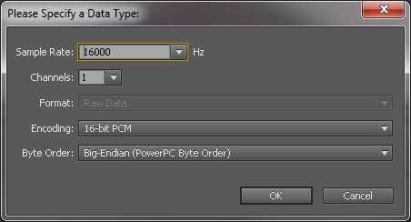
- Select the raw audio file and input the correct parameters
- Click OK
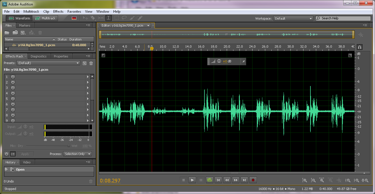
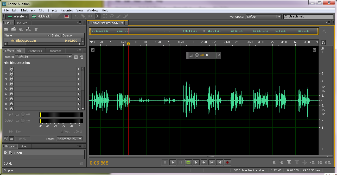
9.4.6.2. Before and After Comparison
- Before audio pre-processing (t8/y16L7g3m7090_1.pcm)
- After audio pre-processing (t8/fileOutput.bin)
9.5. Big Data IPC Example
9.5.1. Introduction
High Performance Computing applications and other Data intensive applications often require passing of Big data buffers between the multi-core processors in an SOC.
The Big Data IPC examples are created mainly to show exchange of big data buffers between cores and is part of the Processor SDK RTOS package.
Currently the example named “simple_buffer_example”, captures the details of exchange of big buffers with both host A15 core and a DSP cores.
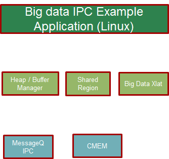
9.5.2. Architecture Overview
The following block diagram shows the various functional blocks used in the example on the cores running TI-RTOS/BIOS.
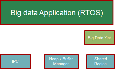
For the small message IPC, sharedRegion and Heap, the modules in the Standard TI IPC package are used.
The BigDataXlat module, which is part of the example code, provides a high level abstraction to take care of Address translation and Cache sync on the big data buffers.
9.5.3. Simple Buffer example: Program Sequence
This section describes the program sequence captured in the example.
The main aim of the overall program is to show the exchange of big data buffers. The sequence is described in words here to sort of walk through the main application code.
Initially, the host sends first message with shared memory init information followed by two more dummy messages to slave core ( all three messages sent in sequence without waiting for reply).
The shared memory region init message conveys the details about the shared memory expected to hold the big data buffers.
Independently, the slave processor receives messages and sends back reply back for each of the messages to the host.
Then the host receives one message from the slave and sends a message with Big data buffer allocated from the Big data heap and filled with an incrementing pattern. (This process is repeated with 10 Big data Buffer messages). Each of these Messages are received by slave and the values in the buffers are updated with a modified incrementing pattern and sent back to the host.
Note the Slave and Host processors checks the expected incrementing pattern for errors.
At this point only 7 Big data buffer messages would have been received. Then the host sends two dummy messages plus one shutdown message to the slave core when receiving the remaining three Big data buffer messages. Totally 10 Big data buffers are exchanged between the cores. The slave core on receiving the shutdown message, shuts itself down and reinitializes itself for future runs.
Then the host receives back the remaining returned messages before shutting down.
Note
The size of the big data buffer is configurable compile time by changing value of the define BIGDATA_SIZE in shared/AppCommon.h
9.5.4. Host Linux example
Note
Host linux example is only available starting from Processor SDK 4.0.0 release for AM57xx platform
Under the host_linux directory the simple_buffer_example is implemented for Host A15 running Linux and DSP core running TI-RTOS.
9.5.4.1. Architecture Updates for Linux
The following block diagram shows the various functional blocks used in the example on the host running linux.
The SharedRegion and HeapMem modules are not currently supported for Linux in the TI Standard IPC package.
The example provides these modules with same/similar API implemented for Linux with some limitations.
The CMEM APIs provide user space allocation of contiguous memory for the Big data buffers.
9.5.4.2. How to Run the Example
The Processor SDK Linux release includes the pre-built binaries for the host_linux example as part of the tisdk-rootfs-image filesystem.
Step 1 : To run the demo, the first step is to make sure there is no other default applications using the same resources. For example, the following command is needed to disable the default OpenCL applications.
systemctl stop ti-mct-daemon.service
Step 2: Switch the firmware running in the DSP. This can be done by using the following steps. Unbind dsp
echo 40800000.dsp > /sys/bus/platform/drivers/omap-rproc/unbind
Note
May need to unbind all the other cores as well to avoid issues.
Update firmware symbolic link
ln -sf /usr/bin/simple_buffer_example/release/server_dsp.xe66 /lib/firmware/dra7-dsp1-fw.xe66
Bind dsp
echo 40800000.dsp > /sys/bus/platform/drivers/omap-rproc/bind
Step 3: Now the Host side application can be run using the following command
/usr/bin/simple_buffer_example/release/app_host
The DSP side log can be checked by typing the following command to dump the trace.
cat /sys/kernel/debug/remoteproc/remoteproc2/trace0
Here is a sample log.
root@am57xx-evm:~# /usr/bin/simple_buffer_example/release/app_host DSP1
--> main:
[523682.897761] omap_hwmod: mmu0_dsp2: _wait_target_disable failed
[523682.903751] omap-iommu 41501000.mmu: 41501000.mmu: version 3.0
[523682.911797] omap-iommu 41502000.mmu: 41502000.mmu: version 3.0
--> Main_main:
--> App_create:
App_create: Host is ready
<-- App_create:
--> App_exec:
CMEM_init success
CMEM_getPool success
CMEM_allocPool success: Allocated buffer 0xaa641000
SharedRegion_setup success
App_taskFxn: SR_1, base 0xaa641000, len=1000000
HeapMem_setup success
HeapMem_create success
App_taskFxn: SR_1 heap, totalSize=16777216,totalFreeSize=16777216,largestFreeSize=16777216
App_taskFxn: SR_1 heap, buf=0x0xaa641080,size=16777216
App_exec: sending message 1
Shared memory phys Addr ffffffffa0000000
App_exec: sending message 2
App_exec: sending message 3
App_exec: message received 1
App_exec: Preparing message 4
App_exec: Sending message 4
App_exec: message received 2
App_exec: Preparing message 5
App_exec: Sending message 5
App_exec: message received 3
App_exec: Preparing message 6
App_exec: Sending message 6
App_exec: message received 4
App_exec: Preparing message 7
App_exec: Sending message 7
App_exec: message received 5
App_exec: Preparing message 8
App_exec: Sending message 8
App_exec: message received 6
App_exec: Preparing message 9
App_exec: Sending message 9
App_exec: message received 7
App_exec: Preparing message 10
App_exec: Sending message 10
App_exec: message received 8
App_exec: Preparing message 11
App_exec: Sending message 11
App_exec: message received 9
App_exec: Preparing message 12
App_exec: Sending message 12
App_exec: message received 10
App_exec: Preparing message 13
App_exec: Sending message 13
App_exec: message received 11
App_exec: Preparing message 14
App_exec: Sending message 14
App_exec: message received 12
App_exec: Preparing message 15
App_exec: Sending message 15
App_exec: message received 13
App_exec: Preparing message 16
App_exec: Sending message 16
App_exec: message received: 14
App_exec: message received: 15
App_exec: message received: 16
App_exec: Data check clean
<-- App_exec: 0
--> App_delete:
<-- App_delete:
<-- Main_main:

 Host: Test Passed
<-- main:
root@am57xx-evm:~#

root@am57xx-evm:~# cat /sys/kernel/debug/remoteproc/remoteproc2/trace0
[      0.000] 18 Resource entries at 0x95000000
[      0.000] [t=0x0002122e] xdc.runtime.Main: --> main:
[      0.000] registering rpmsg-proto:rpmsg-proto service on 61 with HOST
[      0.000] [t=0x003c5d7b] xdc.runtime.Main: NameMap_sendMessage: HOST 53, port=61
[      0.000] [t=0x003d5186] xdc.runtime.Main: --> smain:
[      0.000] [t=0x003e8259] Server: Server_create: server is ready
[      0.000] [t=0x003ecc97] Server: <-- Server_create: 0
[      0.000] [t=0x003f04a4] Server: --> Server_exec:
[     51.571] [t=0x00000008:a56e6a9a] Server: Message received...1
[     51.571] [t=0x00000008:a56f9b77] Server: Shared region entry configured...
[     51.571] [t=0x00000008:a5700cb1] Server: Server_exec: processed id 1, cmd=0x1
[     51.571] [t=0x00000008:a570aea5] Server: Message received...2
[     51.571] [t=0x00000008:a57119fd] Server: Server_exec: processed id 2, cmd=0x0
[     51.571] [t=0x00000008:a571b1e9] Server: Message received...3
[     51.571] [t=0x00000008:a5721eac] Server: Server_exec: processed id 3, cmd=0x0
[     51.571] [t=0x00000008:a5755f6b] Server: Message received...4
[     51.573] [t=0x00000008:a583e61b] Server: Server_exec: processed id 4, cmd=0x2
[     51.573] [t=0x00000008:a584a087] Server: Message received...5
[     51.574] [t=0x00000008:a592c2cc] Server: Server_exec: processed id 5, cmd=0x2
[     51.574] [t=0x00000008:a5937d8c] Server: Message received...6
[     51.575] [t=0x00000008:a5a19aeb] Server: Server_exec: processed id 6, cmd=0x2
[     51.575] [t=0x00000008:a5a2543d] Server: Message received...7
[     51.577] [t=0x00000008:a5b07d15] Server: Server_exec: processed id 7, cmd=0x2
[     51.577] [t=0x00000008:a5b137c0] Server: Message received...8
[     51.578] [t=0x00000008:a5bf5d83] Server: Server_exec: processed id 8, cmd=0x2
[     51.578] [t=0x00000008:a5c019cc] Server: Message received...9
[     51.579] [t=0x00000008:a5ce3dca] Server: Server_exec: processed id 9, cmd=0x2
[     51.579] [t=0x00000008:a5cef75e] Server: Message received...10
[     51.581] [t=0x00000008:a5dd247a] Server: Server_exec: processed id 10, cmd=0x2
[     51.581] [t=0x00000008:a5dde2d9] Server: Message received...11
[     51.582] [t=0x00000008:a5ec04df] Server: Server_exec: processed id 11, cmd=0x2
[     51.582] [t=0x00000008:a5ecc1a3] Server: Message received...12
[     51.583] [t=0x00000008:a5fae91c] Server: Server_exec: processed id 12, cmd=0x2
[     51.583] [t=0x00000008:a5fba4c6] Server: Message received...13
[     51.585] [t=0x00000008:a609d1c1] Server: Server_exec: processed id 13, cmd=0x2
[     51.585] [t=0x00000008:a60a8dd4] Server: Message received...14
[     51.585] [t=0x00000008:a60af96e] Server: Server_exec: processed id 14, cmd=0x0
[     51.585] [t=0x00000008:a60b9229] Server: Message received...15
[     51.585] [t=0x00000008:a60bffd3] Server: Server_exec: processed id 15, cmd=0x0
[     51.585] [t=0x00000008:a60e179b] Server: Message received...16
[     51.585] [t=0x00000008:a60e9727] Server: Server_exec: processed id 16, cmd=0x2000000
[     51.585] [t=0x00000008:a60f3fb7] Server: Server_exec: Data check clean
[     51.585] [t=0x00000008:a60fb280] Server: <-- Server_exec: 0
[     51.585] [t=0x00000008:a6101708] xdc.runtime.Main: DSP: Test Passed
[     51.585] [t=0x00000008:a6109170] Server: --> Server_delete:
[     51.585] [t=0x00000008:a6114fa2] Server: <-- Server_delete: 0
[     51.586] [t=0x00000008:a6127d48] Server: Server_create: server is ready
[     51.586] [t=0x00000008:a612ff93] Server: <-- Server_create: 0
[     51.586] [t=0x00000008:a613620c] Server: --> Server_exec:
root@am57xx-evm:~#
9.5.4.3. How to Re-Build the example
Also source code for the example is included in the Processor SDK Linux release. Once installed the source files can be found in the directory example-applications/big-data-ipc-demo-linux_<version>.
Prerequisites: Also need to have the Processor SDK RTOS release installed to build the DSP side RTOS image. See the instruction in RTOS SDK Getting Started Guide
The example can be rebuilt by using the following commands.
export TI_RTOS_PATH=<TI_RTOS_PROC_SDK_INSTALL_DIR>
make big-data-ipc-demo
(e.g)
export TI_RTOS_PATH=$HOME/ti
make big-data-ipc-demo
The test binaries can be installed into the default filesystem using the command.
make big-data-ipc-demo_install
Note
Rules.make file can be edited to change the DESTDIR where the binaries will be installed.
9.5.4.3.1. Source files
The source files for the example are located at
<processor-sdk_linux-<platform>-<version>/example-applications/big-data-ipc-demo-linux-<version>/host_linux/simple_buffer_example.
The host directory and dsp directory has the corresponding sources. The shared folder contains some common sources. The main sequence for big data IPC can be followed by looking at host/App.c and dsp/Server.c. |
9.5.4.3.2. Memory layout details
The DSP side memory layout can be found in the file host_linux/simple_buffer_example/shared/<platform>/config.bld. Also note the addition of the following section in host_linux/simple_buffer_example/shared/<platform>/rsc_table_dsp.h. Please note the reserved carve-out in the DSP resource table
Note
Make sure this matches what is configured in the linux device tree
- define DSP_CMEM_IOBUFS 0xA0000000
- define PHYS_CMEM_IOBUFS 0xA0000000
- define DSP_CMEM_IOBUFS_SIZE (SZ_1M * 192)
The CMEM area allocated from this region is used for the big data buffers.
9.5.5. Host RTOS example
Under the host_bios directory the simple_buffer_example is implemented for Host A15 and DSP both running TI RTOS/BIOS.
9.5.5.1. How to Run the Example
The Processor SDK RTOS release include the pre-built binaries for the host_bios example under:
processor_sdk_<platform>_<version>/demos/bigdataipc/prebuilt-binaries/<board-name>/simple_buffer_example/release/
Also for the platforms that support boot through SDcard, pre-built boot image or ‘app’ bootable through SBL is located under:
processor_sdk_<platform>_<version>/demos/bigdataipc/prebuilt-binaries/bootimages/host_bios/simple_buffer_example/<board-name>/app
9.5.5.1.1. AM57xx & K2G boards
Pre-requisites
1. Create a bootable SDCard using the procedure here: Creating SD card in Windows or Create SD card in Linux
2. Connect the UART on the hardware to the Host. ( Configure the terminal/console to Baud Rate= 115200, Data Bits= 8 , Parity= None, Flow Control= Off )
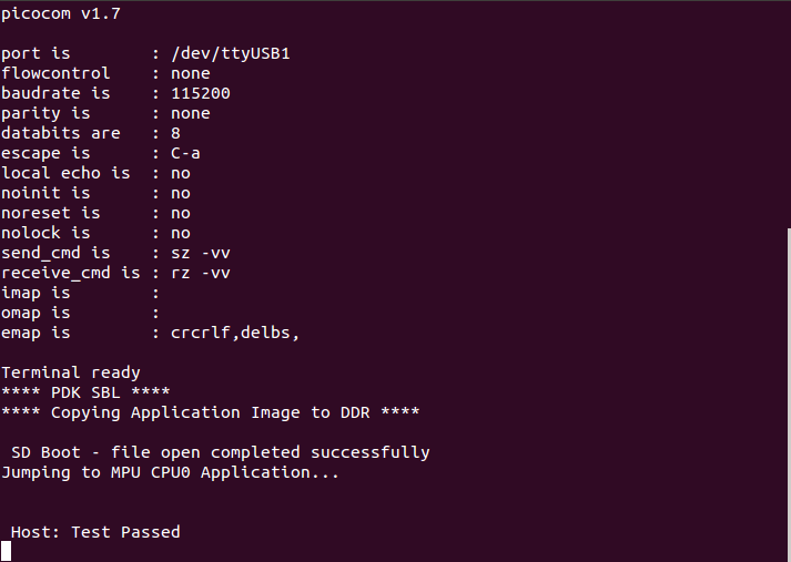
Procedure
- Copy/overwrite the pre-built boot image ‘app’ corresponding to the board to a bootable SD Card
- Insert the SD card into the board
- Boot/Reboot the board
The application will be loaded and run automatically and the “Host: Test Passed” message will be printed to the UART console.
9.5.5.1.2. K2H, K2K, K2L, K2E Boards
The prebuilt elf binaries of Host and DSP images can be loaded through CCS to the appropriate cores and run.
9.5.5.2. How to Re-Build the Example
The bigdata ipc examples can be built from the Processor SDK top level directory using the following steps
1. Build environment setup
Linux host
cd  <processor_sdk_<platform>_<version>
export SDK_INSTALL_PATH=<Base directory where Processor SDK is installed>
source setupenv.sh
Windows host
cd  <processor_sdk_<platform>_<version>
set SDK_INSTALL_PATH=<Base directory where Processor SDK is installed>
setupenv.bat
2. Build
make bigdataipc_examples
This creates the elf binaries for both the host and DSP cores. And the binaries can be installed using
make bigdataipc_examples_install
(NOTE: The above command installs the elf binaries under the prebuilt-binaries location mentioned above. Need to convert the prebuilt elf binaries into bootable images refer to Processor SDK RTOS Boot)
Source files
The source files for the example are located at
<processor_sdk_<platform>_<version>/demos/bigdataipc/host_bios/simple_buffer_example.
The host directory and dsp directory has the corresponding sources. The shared folder contains some common sources. The main sequence for big data IPC can be followed by looking at host/App.c and dsp/Server.c.
9.6. TI-RTOS Kernel Example
9.6.1. Overview
The SYS/BIOS examples gets user started with development of code using a real-time operating system. These are simple examples that does not get into details of software components provided in the SDK.
Note
All instructions on this wiki have been created using CCSv6 but should apply to CCSv7. Please report any issues by posting on E2E forums
9.6.2. ARM Cortex-A15
The hello example serves as a basic sanity check program for SYS/BIOS. It demonstrates how to print the string ‘hello world’ to stdout. As a sample we will use the AM572x device to describe the steps. The same steps can be used for create hello world examples for A15 cores in Keystone 2 family of devices.
Note
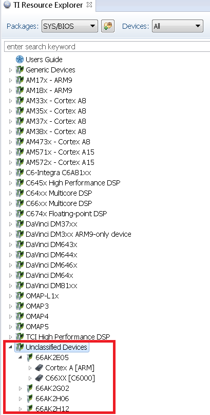
- The K2G, K2E and K2H devices, can be located under Unclassified devices in the Resource Explorer. Refer below Screenshot for Keystone II
1. Create a work space folder (tiam_572x_hello_workspace) under ti folder to be used for Hello Example project, and start CCS. You may be prompted with New Products Discovered, so select all and click on Finish
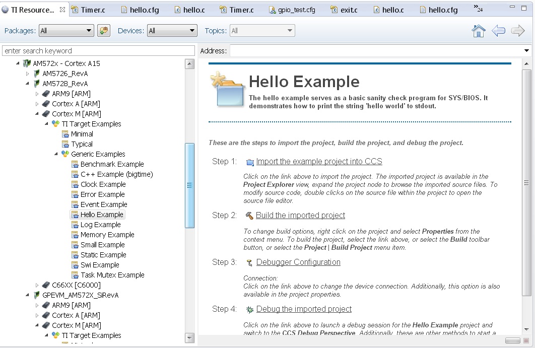
- On CCS click View –> Resource Explorer (Examples).
3. On SYS/BIOS scroll down to AM572X –> Cortex A –> Generic Example –> click on Hello Example.
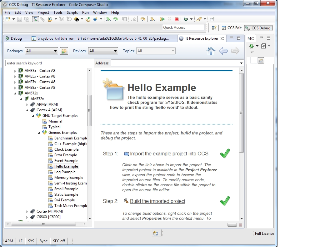
4. To import Hello Example, on the right window click on step 1. Import The Example to CCS Project.
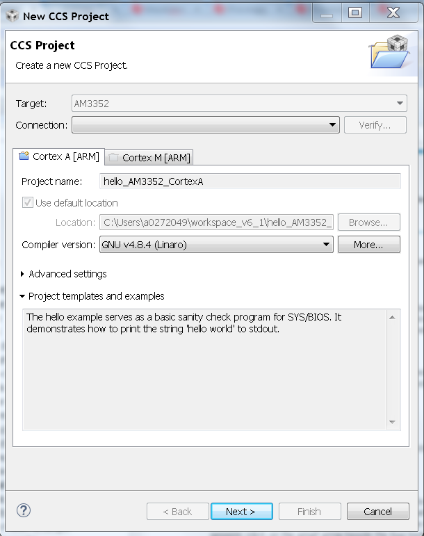
- On New CCS Project window enter project name and then click Next.
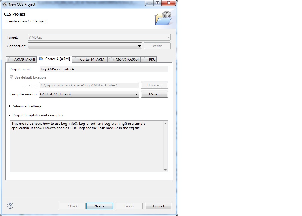
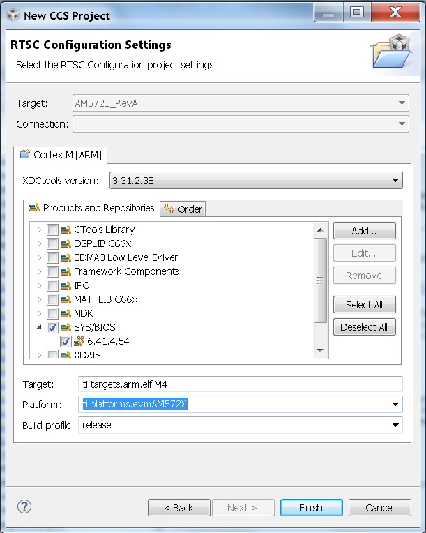
6. On RSTC window select platform name: ti.platforms.evmAM572X and check that the target is set to gnu.targets.arm.A15F
- Click Finish. Your project should show up on Project Explorer window.
8. To get log message to print on console add this variable to hello.cfg file:
Note
You also need to replace the nosys library in linker with rdimon which is the Semi-Hosting enabled BSP library.
Right click on project –> Show Build Settings... –> Build –> GNU Linker –> Libraries
9. Build Hello Example project by Right click on Hello Project and click Build project.
10. Create new target configuration (if one doesn`t exist) as described in here Create Target Configuration File for EVM
11. Right click on the target configuration and Launch target configurations.
- Right click CortexA15_0 and connect target.
12. Load and run Hello Example out file. You should see Hello World string displayed on console window.
9.6.3. ARM Cortex-A9
The hello example serves as a basic sanity check program for SYS/BIOS. It demonstrates how to print the string ‘hello world’ to stdout.
1. Create a work space folder (\ti\am_437x_hello_workspace) under ti folder to be used for Hello Example project, and start CCS. You may be prompted with New Products Discovered, so select all and click on Finish
- On CCS click View –> Resource Explorer (Examples).
3. On SYS/BIOS scroll down to AM4378 –> Cortex A –> Generic Example –> click on Hello Example.
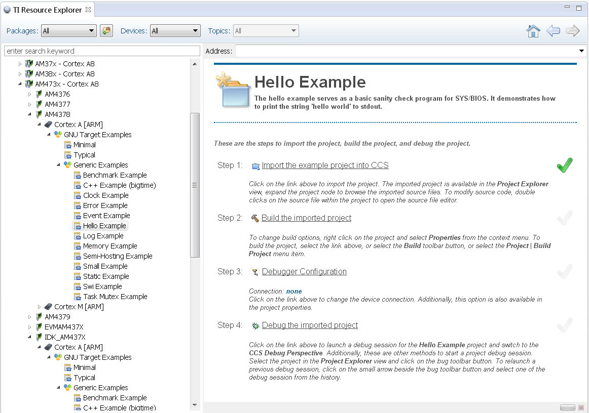
4. To import Hello Example, on the right window click on step 1. Import The Example to CCS Project.
- On New CCS Project window enter project name and then click Next.
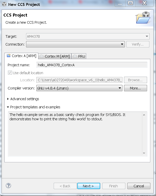
6. On RSTC window select platform name: ti.platforms.evmAM437X and check that the target is set to gnu.targets.arm.A9F
- Click Finish. Your project should show up on Project Explorer window.
8. To get log message to print on console add this variable to hello.cfg file:
Note
You also need to replace the nosys library in linker with rdimon which is the Semi-Hosting enabled BSP library.
Right click on project –> Show Build Settings... –> Build –> GNU Linker –> Libraries
9. Build Hello Example project by Right click on Hello Project and click Build project.
10. Create new target configuration (if one doesn`t exist) as described here Create Target Configuration File for EVM
11. Right click on the target configuration and Launch target configurations.
- Right click CortexA9_0 and connect target.
12. Load and run Hello Example out file. You should see Hello World string displayed on console window.
9.6.4. ARM Cortex-A8
The hello example serves as a basic sanity check program for SYS/BIOS. It demonstrates how to print the string ‘hello world’ to stdout.
1. Create a work space folder (\ti\am_335x_hello_workspace) under ti folder to be used for Hello Example project, and start CCS. You may be prompted with New Products Discovered, so select all and click on Finish
- On CCS click View –> Resource Explorer (Examples).
3. On SYS/BIOS scroll down to AM3352 –> Cortex A –> Generic Example –> click on Hello Example.
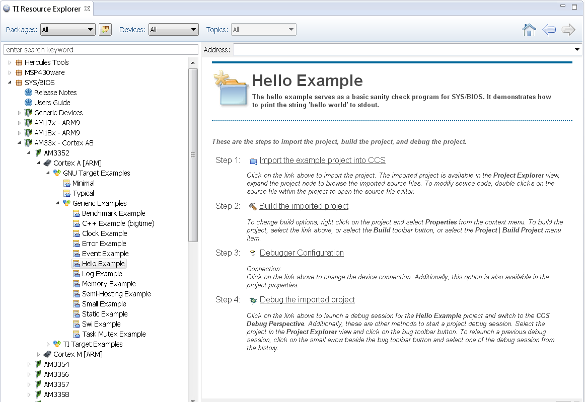
4. To import Hello Example, on the right window click on step 1. Import The Example to CCS Project.
- On New CCS Project window enter project name and then click Next.
6. On RSTC window select platform name: ti.platforms.evmAM335X and check that the target is set to gnu.targets.arm.A8F
- Click Finish. Your project should show up on Project Explorer window.
8. To get log message to print on console add this variable to hello.cfg file:
Note
You also need to replace the nosys library in linker with rdimon which is the Semi-Hosting enabled BSP library.
Right click on project –> Show Build Settings... –> Build –> GNU Linker –> Libraries
9. Build Hello Example project by Right click on Hello Project and click Build project.
10. Create new target configuration (if one doesn`t exist) as described here Create Target Configuration File for EVM
11. Right click on the target configuration and Launch target configurations.
- Right click CortexA8_0 and connect target.
12. Load and run Hello Example out file. You should see Hello World string displayed on console window.
9.6.5. ARM Cortex-M4
The hello example serves as a basic sanity check program for SYS/BIOS. It demonstrates how to print the string ‘hello world’ to stdout.
1. Create a work space folder (\ti\am_572x_hello_workspace) under ti folder to be used for Hello Example project, and start CCS. You may be prompted with New Products Discovered, so select all and click on Finish
- On CCS click View –> Resource Explorer (Examples).
3. on SYS/BIOS scroll down to AM572X –> Cortex M –> Generic Example –> click on Hello Example.
4. To import Hello Example, on the right window click on step 1. Import The Example to CCS Project.
- On New CCS Project window enter project name and then click Next.
6. On RSTC window select platform name: ti.platforms.evmAM572X and check that the target is set to gnu.targets.arm.elf.M4
- Click Finish. Your project should show up on Project Explorer window.
8. Build Hello Example project by Right click on Hello Project and click Build project.
9. Launch target configurations using appropriate emulator to connect to AM572X EVM.
10. Right click CortexA15_0 and connect target. From the Scripts menu select AM572x Multicore Initialization->IPU1SSClkEnable_API.
11. Connect to the Cortex_M4_IPU1_C0. Load and run Hello Example out file. You should see Hello World string displayed on console window.
9.6.6. DSP C66x
The hello example serves as a basic sanity check program for SYS/BIOS. It demonstrates how to print the string ‘hello world’ to stdout. As a sample we will use the AM572x device to describe the steps but the same steps can be used for create hello world examples for C66x cores in Keystone I and Keystone 2 family of devices.
Note
- The C66x examples corresponding Keystone I devices can be located under C66x Multi-core DSP devies in the Resource Explorer. Refer below screenshot
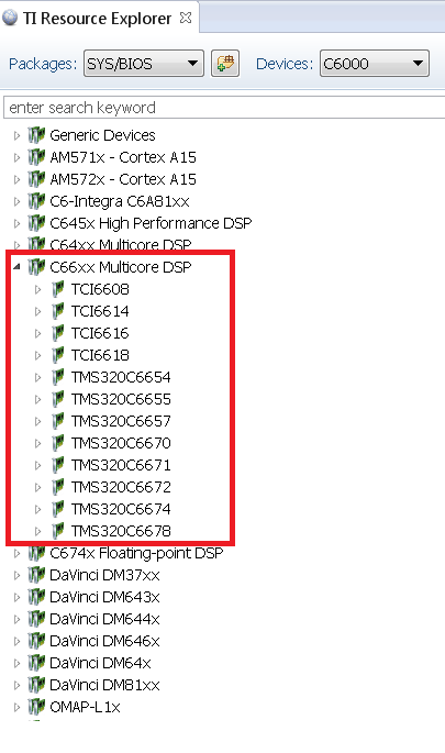
Note
- The K2G, K2E and K2H devices, can be located under Unclassified devices in the Resource Explorer. Refer below screen shot
1. Create a work space folder (tiam_572x_hello_workspace) under ti folder to be used for Hello Example project, and start CCS. You may be prompted with New Products Discovered, so select all and click on Finish
- On CCS click View –> Resource Explorer (Examples).
3. on SYS/BIOS scroll down to AM572X –> C66x –> Generic Example –> click on Hello Example.
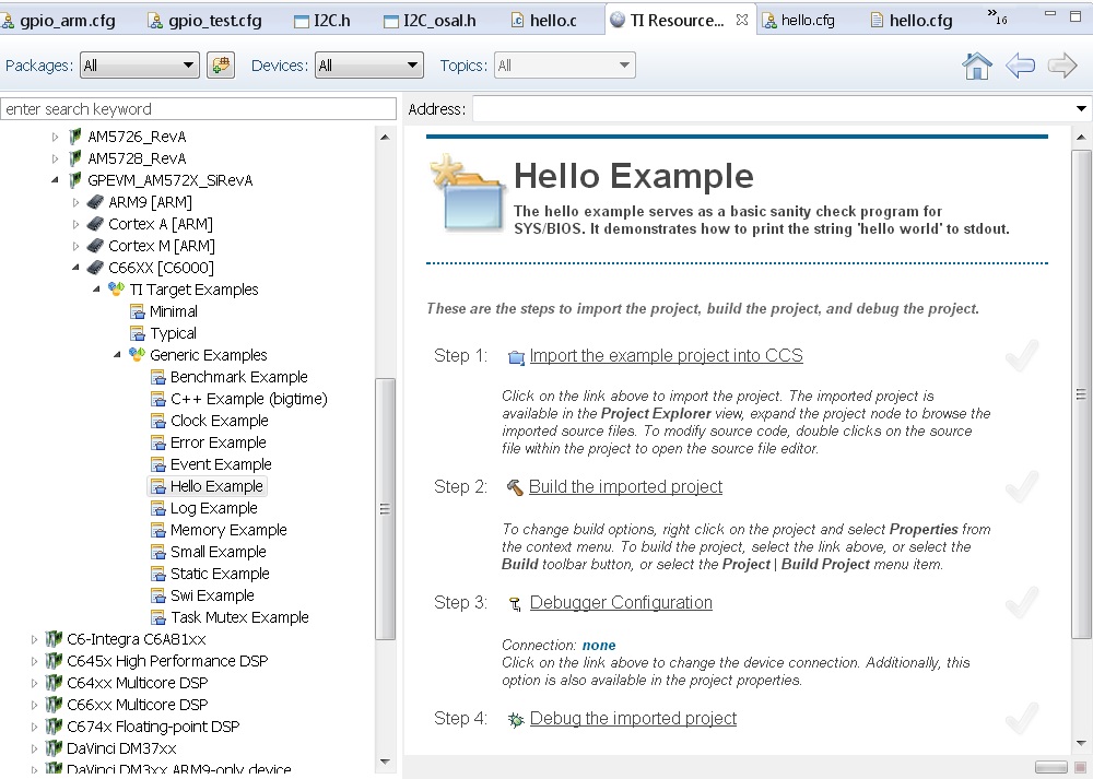
4. To import Hello Example, on the right window click on step 1. Import The Example to CCS Project.
- On New CCS Project window enter project name and then click Next.
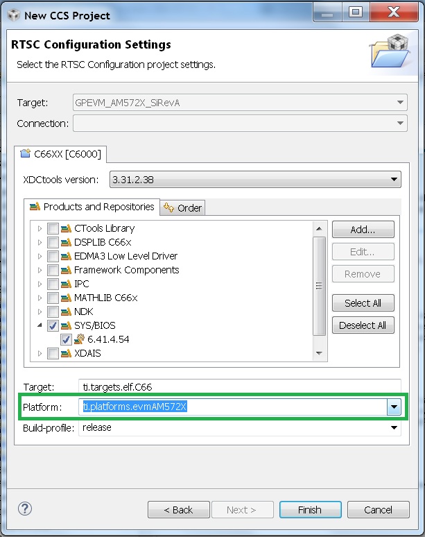
6. On RSTC window select platform name: ti.platforms.evmAM572X and check that the target is set to ti.targets.elf.C66 (Auto populated)
- Click Finish. Your project should show up on Project Explorer window.
8. Build Hello Example project by Right click on Hello Project and click Build project.
10. Create new target configuration (if one doesn`t exist) as described here.
11. Right click on the target configuration and Launch target configurations.
12. Right click CortexA15_0 and connect target. From the Scripts menu select AM572x Multicore Initialization->DSP1SSClkEnable_API.
13. Route the GPTimer5 suspend ctrl signal to the DSP using the Scripts menu GP timer Suspend Ctrl -> GPTimer5SuspendCtl_DSP1SS_BIOS as described here.
14. Connect to C66x_DSP1 Load and run Hello Example out file. You should see Hello World string displayed on console window.
9.6.7. DSP C674x
The hello example serves as a basic sanity check program for SYS/BIOS. It demonstrates how to print the string ‘hello world’ to stdout. As a sample we will use the C6748 device to describe the steps but the same steps can be used for create hello world examples for C674x cores in OMAPL1x/DA8x family of devices.
Note
- Locate the appropriate device that you are using to make sure the correct SYSBIOS platform definiition gets used in the build
1. Create a work space folder ( Eg. tirtos_hello_workspace) that can be used for Hello Example project, and start CCS. You may be prompted with New Products Discovered, so select all and click on Finish Note: at this stage the version of SYSBIOS and corresponding dependencies are assumed to be discovered by CCS. If not please follow the steps described here: Discovering_SDK_products
- On CCS click View –> Resource Explorer Classic (Examples).
3. on SYS/BIOS scroll down to C6748 /OMAPL1x and select –> C674x –> Generic Example –> click on Hello Example.
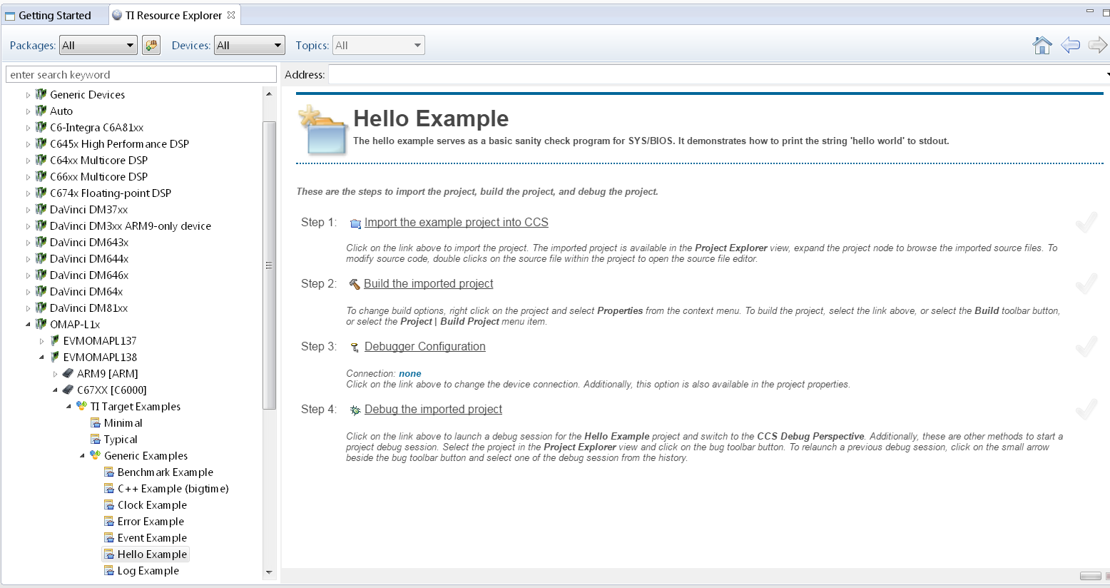
4. To import Hello Example, on the right window click on step 1. Import The Example to CCS Project.
- On New CCS Project window enter project name and then click Next.
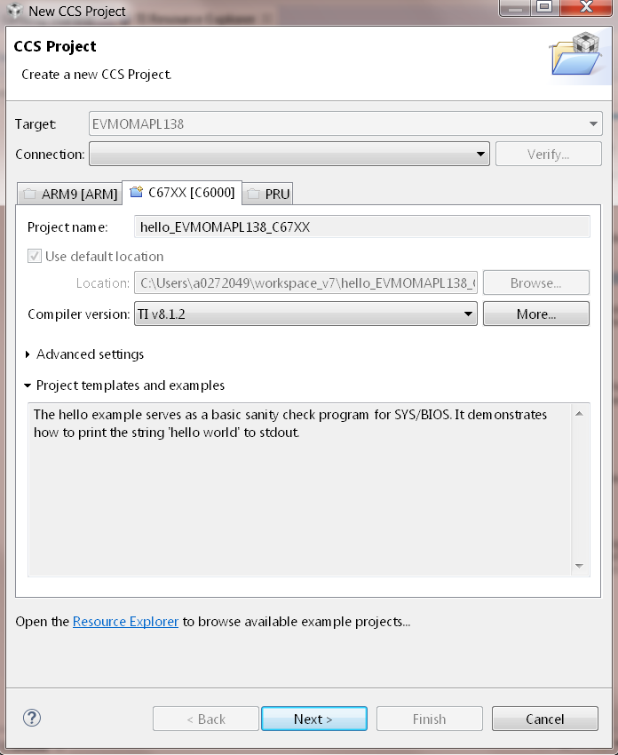
6. On RSTC window select platform name: ti.platforms.evmc6748 and check that the target is set to ti.targets.elf.C674 (Auto populated)
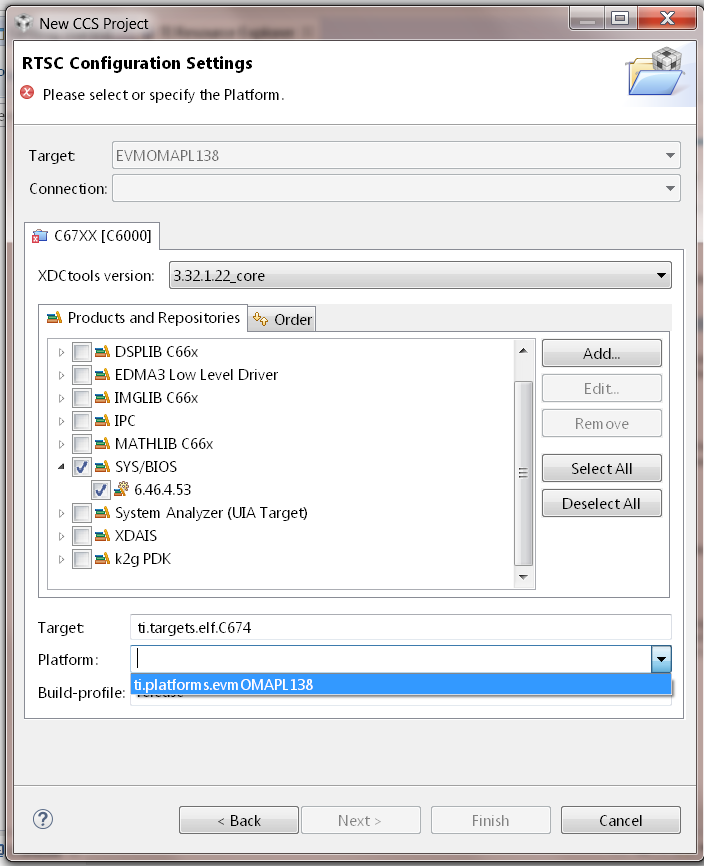
- Click Finish. Your project should show up on Project Explorer window.
8. Build Hello Example project by Right click on Hello Project and click Build project.
10. Create new target configuration (if one doesn`t exist) as described here.
11. Right click on the target configuration and Launch target configurations.
12. Developers can Connect to the C674x on OMAPL137/C6747/C6748 can connect directly to the DSP. For OMAPL138 device, you will need to connect to the ARM as this is ARM master boot device and ARM needs to power up the DSP You should see the following log in the Console
C674X_0: Output:   Target Connected.
C674X_0: Output:    ---------------------------------------------
C674X_0: Output:    Memory Map Cleared.
C674X_0: Output:    ---------------------------------------------
C674X_0: Output:    Memory Map Setup Complete.
C674X_0: Output:    ---------------------------------------------
C674X_0: Output:    PSC Enable Complete.
C674X_0: Output:    ---------------------------------------------
C674X_0: Output:    PLL0 init done for Core:300MHz, EMIFA:25MHz
C674X_0: Output:    DDR initialization is in progress....
C674X_0: Output:    PLL1 init done for DDR:150MHz
C674X_0: Output:    Using DDR2 settings
C674X_0: Output:    DDR2 init for 150 MHz is done
C674X_0: Output:    ---------------------------------------------
13. Connect to C674x_DSP1 Load and run Hello Example out file. You should see Hello World string displayed on console window.
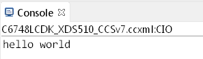
9.6.8. Usage Notes
After execution of the hello world examples on the core, the CCS Editor may report “Can’t find a source file” error messages when you pause or the application exits/aborts after completion. This occurs due to source files from SYSBIOS or XDC packages not being in the default search path of the CCS Editor. when you run into this issue, you can navigate to the file using Locate file option in the Editor. Once you provide the location the CCS Editor will be able to locate all the other required files from that package based on relative path.
For example, when running SYS/BIOS Hello Example using AM57x-GP EVM if you see the message
Can't find a source file at "/db/ztree/library/trees/xdctargets/xdctargets-i02/src/gnu/targets    /arm/rtsv7A/syscalls.c"
Locate the file or edit the source lookup path to include its location. The above file is located  under file path ${PROC_SDK_DIR}\bios_6_42_02_29\packages\gnu\targets\arm\rtsv7A
You can also prevent these issues by adding the Processor SDK components to file search path under Windows->Preferences options in CCS GUI.
9.6.9. Known Issues
- SYS/BIOS examples for Cortex-A15 generate linker errors due to the FPU related flags
Some versions of CCS are impacted by linker setting used in CCS RTOS templates and may need some manual modification to set the correct -mfpu, -mcpu and -march. If you are seeing VFP errors in the link step, you are most likely running into this issue. To correct this issue please check the resolution here: https://e2e.ti.com/support/development_tools/code_composer_studio/f/81/t/539973
9.7. No OS (Bare Metal) Example
9.7.1. Overview
The bare-metal examples gets user started with development of code without an operating system. These are simple examples that does not get into details of software components provided in the SDK. Consequently, make sure there are no SD cards installed on the EVM with an OS prior to exploring the following examples.
If you face any problems with CCS or JTAG, see try these troubleshooting steps.
Note
All instructions on this wiki have been created using CCSv6 but should apply to CCSv7. Please report any issues by posting on E2E forums
9.7.2. ARM Cortex-A15
In this article, we take a look at creating bare-metal hello world examples for Cortex A15 core using pre-built templates in CCS. As a sample we will use the AM572x device to describe the steps but the same steps can be used for create hello world examples for Cortex A15 cores in the Keystone 2 family of devices.
Note
- Only major difference between A15 examples for AM572x and Keystone 2 is that the Keystone 2 device contain MSMC memory instead of OCMC memory as the shared memory.
- For K2G devices, the hello world template will be created with the .lds file that specifies MSMC and DDR memory sections. For K2E and K2H, the CCS template doesn`t populate the .lds file. K2H & K2E users can choose to use 66AK2G02.lds located at ccsv6ccs_basearminclude as reference to add .lds file to their hello world projects.
- Start CCS and create a work space for generating the project.
- Click on File menu option and select New–> CCS Project.
3. Select Target as AM572x -Cortex A15 and GPEVM_AM572x as shown in the image
4. Select Cortex A setting in the options below and provide name of the project as “hello_world” and use default Advanced settings for the project. If the Default settings uses “TI ARM compiler 5.x.x” switch to GNU Linaro 4.8.4 (or higher) tool chain for A15 and check the build little endian ELF binary for the A15 core. Under Project templates and examples, select Basic Examples-> Hello World
Click Finish after you are done to allow CCS to auto generate the project from the template Basic Examples-> Hello World.
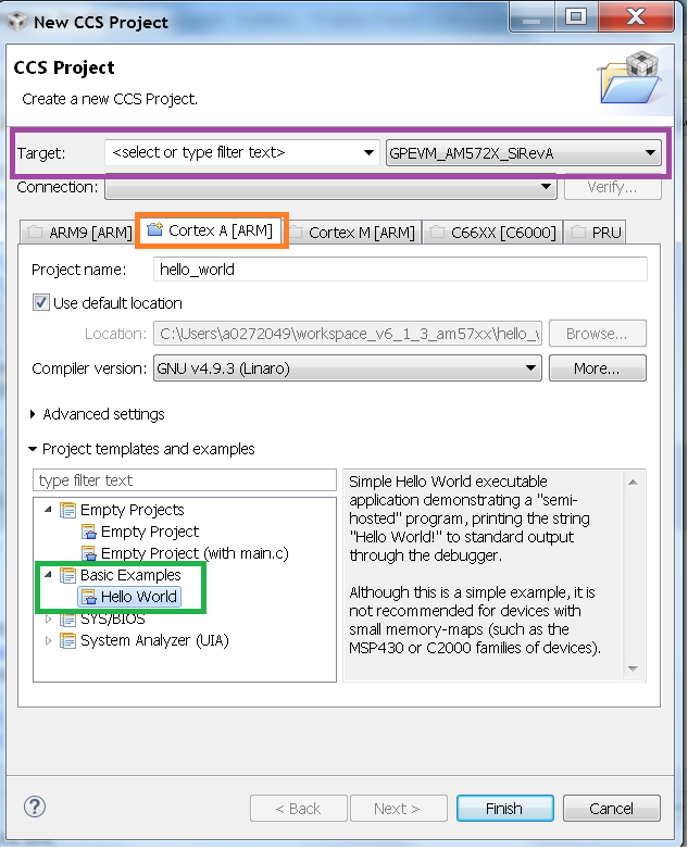
5. The generated CCS project contains source file main.c, ARM assembly code startup_ARMCA15.S and a linker command file AM572x.lds. Please modify the main.c file by adding the following highlighted code lines and save main.c file.
Note
For Keystone2 users, the startup_ARMCA15.S and .lds file is not auto populated by CCS. To add these file, right click the project and add files and locate the 66AK2Gxx.lds and startup_ARMCA15.S under the file path ccsvX/ccs_base/arm/include and add them to the project
6. Ensure that CCSv6 generated linker command file AM572x.lds contains the following Memory configurations.
Note
For Keystone 2 devices, replace all the OCMC_RAM# regions in the lds file and replace it with MSMC memory section as shown below. Refer to 66AK2G02.lds file in ccs installation under directory path ccsv6ccs_basearminclude
MSMC : o=0x0c000000, l = 0x00600000 /* 6MB Muticore shared memory */
Note
The .lds file expects users to provide STACKSIZE and HEAPSIZE from linker settings. To provide these settings got to Build Settings GNU Linker add the following to the Symbols section. Keystone II devices require this to be done explicitly in the linker settings
STACKSIZE=10000
HEAPSIZE=400
7. Right click on the project and select Build Project, to build the project and generate hello_world.out.
8. Launch target configuration using your emulator to connect to AM572X EVM as described in the Processor SDK RTOS Getting Started Guide.
- Right click CortexA15_0 and select connect target.
10. Initialize DDR configuration. On CCS –> Scripts –> DDR configurations –> AM572_DDR3_532MHz_config
11. Load and run hello_world.out example file. You should see Hello_world string displayed on CCS console window.
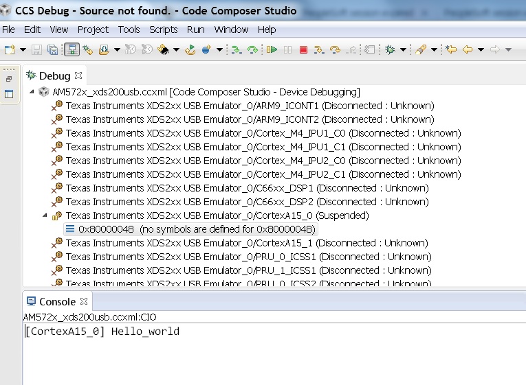
Note
- If the example does not load correctly in the first attempt, reload and ensure ARM core starts at main.
- If the ARM loads correctly but you don`t see any output then check to see if the GNU linker is linking to Semihosting library (librdimon) in the linker setting. If it is not linked go to GNU linker settings in CCS project and add “rdimon” to the libraries that are linked
9.7.3. ARM Cortex-A9
- Start CCSv6 and create a work space for generating the project.
Note
CCSv6.1.1 doesn`t contain a hello world project template for Cortex A9 core using GNU Linaro 4.8.x tool chain. Due to code compatibility of Cortex A8 and cortex A9 platforms, We recommend that you create a project for Cortex A8 platform like AM335x using the GNU Linaro tool chain and then use the code to test hello world application on the Cortex A9 on the AM437x platform. If you wish to use TI ARM compiler 5.2.x, then you can use the default hello world template in CCSv6 for the Cortex A9 on AM437x
2. Click on File menu option and select New–> CCS Project. Steps assume that user is using GN Linaro tool chain for Cortex A9.
3. Select Target as AM33xx -Cortex A8 and appropriate target Board setting as shown in the image
4. Select Cortex A8 setting in the options below and provide name of the project as “hello_world_a9” and use default Advanced settings for the project. If the Default settings uses “TI ARM compiler 5.x.x” switch to GNU Linaro 4.8.4 (or higher) tool chain for A9 and check the build little endian ELF binary for the A9 core. Click Finish after you are done to allow CCS to auto generate the project from the template Basic Examples-> Hello World.
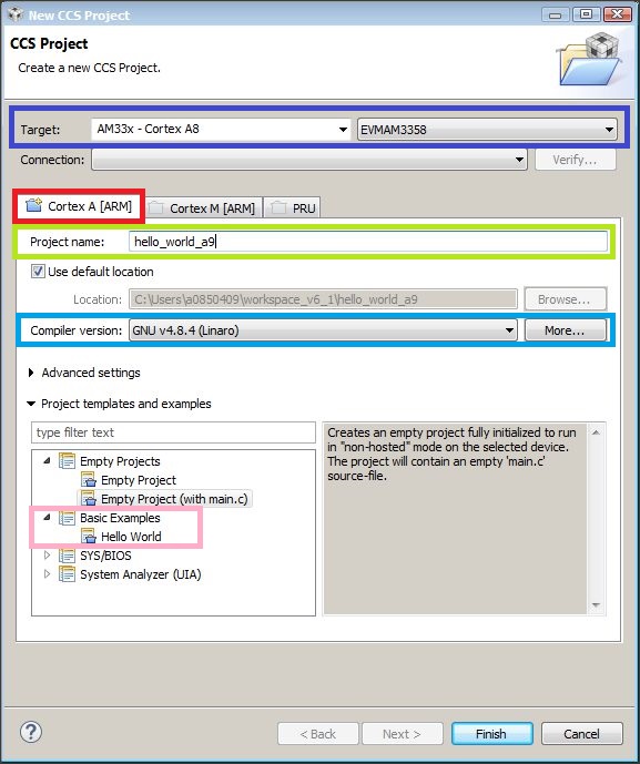
5. The generated CCS project contains source file main.c, ARM assembly code startup_ARMCA8.S and a linker command file AM335x.lds. The startup file does some basic setup and there is no difference between A8 and A9, so it can be used directly on A9 target. Ensure the main.c file contains the following code
- Ensure that CCSv6 generates the linker command file AM335x.lds.
Note
An optional step is to modify the section definition in AM437x.lds file if you wish to introduce more sections or partition the existing sections. If you renamed the startup file from startup_ARMCA8.S to startup_ARMCA9.S in your project, then the linker command file needs to be updated as well for code section placement: from startup_ARMCA8.o (.text) to startup_ARMCA9.o (.text)
- Now build the project to generate hello_world.out file.
8. Launch target configurations using your emulator to connect to AM335X EVM as described in the Getting Started Guide.
9. Right click CortexA9 and connect target. The on target functionality in the GEL will initialize the clocks and DDR.
10. Load and run hello_world_a9.out file. You should see Hello World! string displayed on CCS console window.
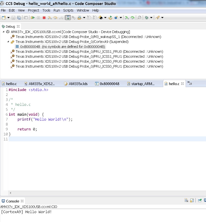
Note
If the example does not load correctly in the first attempt, reload and ensure ARM core starts at main.
9.7.4. ARM Cortex-A8
- Start CCSv6 and create a work space for generating the project.
- Click on File menu option and select New–> CCS Project.
3. Select Target as AM33xx -Cortex A8 and appropriate target Board setting as shown in the image
4. Select Cortex A8 setting in the options below and provide name of the project as “hello_world_a8” and use default Advanced settings for the project. If the Default settings uses “TI ARM compiler 5.x.x” switch to GNU Linaro 4.8.4 (or higher) tool chain for A8 and check the build little endian ELF binary for the A8 core. Click Finish after you are done to allow CCS to auto generate the project from the template Basic Examples-> Hello World.
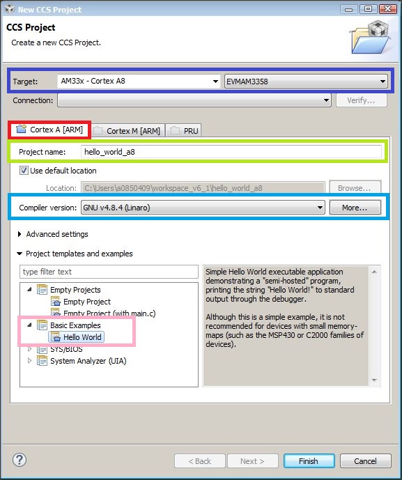
5. The generated CCS project contains source file hello.c, ARM assembly code startup_ARMCA8.S and a linker command file AM335x.lds. Ensure the main.c file contains the following code
- Ensure that CCSv6 generates the linker command file AM335x.lds.
Note
An optional step is to modify the section definition in AM335x.lds file if you wish to introduce more sections or partition the existing sections.
- Now build the project to generate hello_world_a8.out file.
8. Launch target configurations using your emulator to connect to AM335X EVM as described in the Getting Started Guide.
9. Right click CortexA8 and select connect target. The on target functionality in the GEL will initialize the clocks and DDR.
10. Load and run hello_world_a8.out file. You should see Hello World! string displayed on CCS console window.
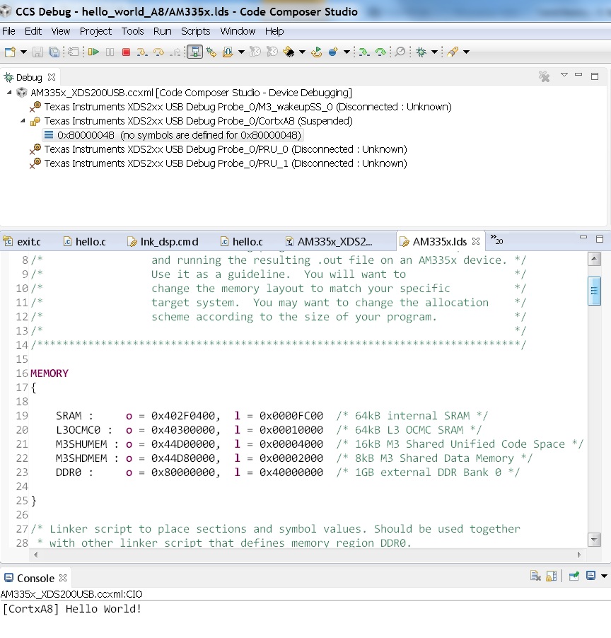
Note
If the example does not load correctly in the first attempt, reload and ensure ARM core starts at main.
9.7.5. ARM Coretex-M4
- Start CCSv6 and create a work space for generating the project.
- Click on File menu option and select New–> CCS Project.
3. Select Target as AM572x -Cortex M4 and GPEVM_AM572x as shown in the image
4. Select Cortex M setting in the options below and provide name of the project as “hello_world_m4” and use default Advanced settings for the project. Click Finish after you are done to allow CCS to auto generate the project from the template Basic Examples-> Hello World. The Default settings uses “TI ARM compiler 5.x.x” tool chain for cortex M4 and sets the build for little endian ELF binary for the M4 core.
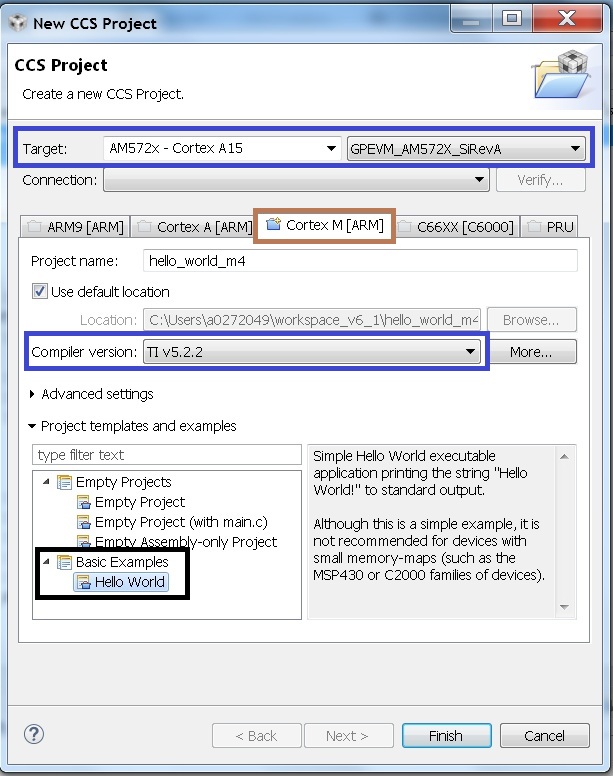
5. The generated CCS project contains only one source file hello.c. Ensure the main.c file contains the following code
6. CCSv6 includes a default linker command file(AM57xx_CM4.cmd) for the M4 (IPU) core which will place code into appropriate device memory. The linker command file has the following memory sections.
The linker command file is designed to place code in OCMC memory with interrupt vectors and .intc_txt generated by the compiler being place in device internal memory.
Note
- Please note that if the device GEL files are setting up MMU for the core then the code will not load correctly on the core and will cause a CPU exception. We recommend that you modify the linker command file appropriately to match the MMU settings in the GEL file. The linker command file in all CCS releases prior to CCS 6.1.3 don`t account for this MMU Setting in AM57xx GEL files. Please modify the OCMC addresses to the logical address set in the GEL file
- An optional step is to modify the section definition in AM57xx_CM4.cmd file if you wish to introduce/partition existing sections or place the code in different memory section.
- Now build the project to generate hello_world_m4.out.
8. Launch target configurations using your emulator to connect to AM572X EVM as described in the Getting Started Guide
9. In order to wake up the M4 core from A15, Go to Menu option Scripts->AM572x_Multicore_Initialization->IPU1SSClkEnable_API. Refer to the Processor_SDK_RTOS_Setup_CCS.
You should see the following log in the Console
CortexA15_0: GEL Output: --->>> IPU1SS Initialization is in progress ... <<<---
CortexA15_0: GEL Output: --->>> IPU1SS Initialization is DONE! <<<---
11. Select and Connect to Cortex_M4_IPU1_C0. Load and run Hello_Example_m4.out file. You should see Hello World string displayed on console window.
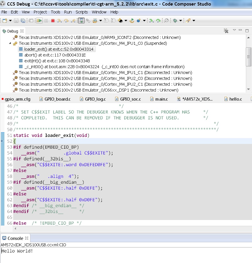
Note
If the example does not load correctly in the first attempt, reload and ensure ARM core starts at main.
9.7.6. DSP C66x
In this article, we take a look at creating bare-metal hello world examples for C66x core using pre-built templates in CCS. As a sample we will use the AM572x device to describe the steps but the same steps can be used for create hello world examples for C66x cores in the Keystone 2 family of devices.
Note
Only major difference C66x examples for AM572x and Keystone 2 is that the Keystone 2 device contain MSMC memory instead of OCMC memory as the shared on chip memory.
- Start CCSv6 and create a work space for generating the project.
- Click on File menu option and select New–> CCS Project.
- Select Target as AM572x -C66xx and GPEVM_AM572x as shown in the image
4. Select C66XX [C6000] DSP setting in the options below and provide name of the project as “hello_world_dsp” and use default Advanced settings for the project. Click Finish after you are done to allow CCS to auto generate the project from the template Basic Examples-> Hello World. The Default settings uses “TI CG Tools compiler 8.x.x” tool chain for C66x and sets the build for little endian ELF binary for the C66x core.
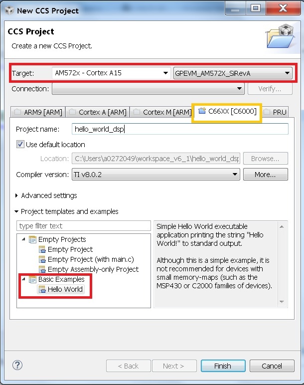
5. The generated CCS project contains only one source file hello.c. Ensure the main.c file contains the following code
6. CCSv6 includes a default linker command file(AM57xx_C66.cmd) for the C66x DSP core which will place code into appropriate device memory. The linker command file has the following memory sections.
The linker command file is designed to place code in OCMC memory.
Note
For Keystone 2 devices, replace all the OCMC_RAM# regions in the lds file and replace it with MSMC memory section as shown below.
MSMC : o=0x0c000000, l = 0x00600000 /* 6MB Muticore shared memory */
Note
An optional step is to modify the section definition in linker command file if you wish to introduce/partition existing sections or place the code in different memory section.
- Now build the project to generate hello_world_dsp.out.
8. Launch target configurations using your emulator to connect to AM572X EVM as described in the Getting Started Guide
9. In order to wake up the DSP1 core from A15, Go to Menu option Scripts->AM572x_Multicore_Initialization->DSP1SSClkEnable_API. Refer to the Processor_SDK_RTOS_Setup_CCS.
You should see the following log in the Console
CortexA15_0: GEL Output: --->>> DSP1SS Initialization is in progress ... <<<---
CortexA15_0: GEL Output: DEBUG: Clock is active ...
CortexA15_0: GEL Output: DEBUG: Checking for data integrity in DSPSS L2RAM ...
CortexA15_0: GEL Output: DEBUG: Data integrity check in GEM L2RAM is sucessful!
CortexA15_0: GEL Output: --->>> DSP1SS Initialization is DONE! <<<---
10. Select and Connect to C66x_DSP1. Load and run hello_world_dsp.out file. You should see Hello World string displayed on console window.
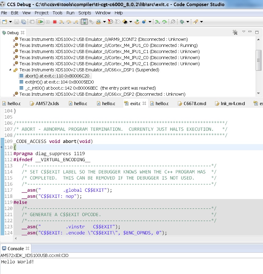
9.7.7. DSP C674x
In this article, we take a look at creating bare-metal hello world examples for C674x core using pre-built templates in CCS. As a sample we will use the C6748 LCDK device to describe the steps but the same steps can be used for create hello world examples for C674x cores in the OMAPL13x/C647x/DA8x family of devices.
Note
All the C674x DSP cores on in OMAPL13x/C674x/DA8x have the same memory map so modification are limited to selecting the correct platform when generating the project
- Start CCS and create a work space for generating the project.
- Click on File menu option and select New–> CCS Project.
- Select Target as OMAPLx -C674xx and LCDK674x as shown in the image
4. Select C67XX [C6000] DSP setting in the options below and provide name of the project as “hello_world_lcdk674x” and use default Advanced settings for the project. Click Finish after you are done to allow CCS to auto generate the project from the template Basic Examples-> Hello World. The Default settings uses “TI CG Tools compiler 8.x.x” tool chain for C674x and sets the build for little endian ELF binary for the C674x core.
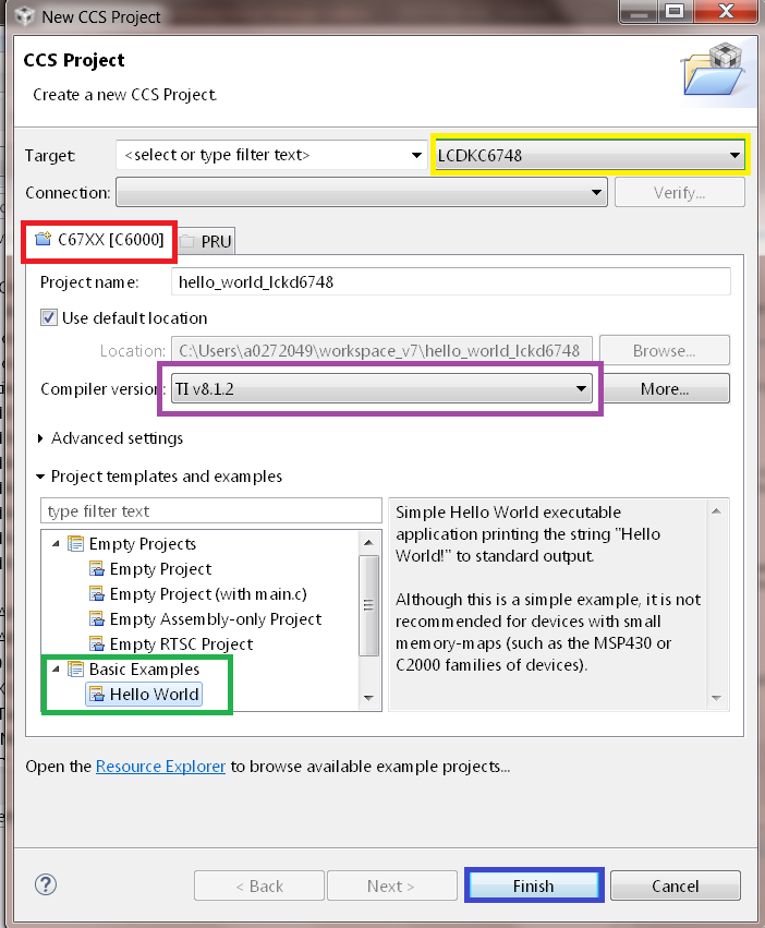
5. The generated CCS project contains only one source file hello.c. Ensure the main.c file contains the following code
6. CCS includes a default linker command file(C6748.cmd) for the C674x DSP core which will place code into appropriate device memory. The linker command file has the following memory sections.
The linker command file is designed to place code in OCMC memory.
Note
For OMAPL13x/C674x devices, the linker command file places code in the SHRAM memory section as shown below.
 SECTIONS
{
 .text          >  SHRAM
 .stack         >  SHRAM
 .bss           >  SHRAM
  .......
}
Note
An optional step is to modify the section definition in linker command file if you wish to introduce/partition existing sections or place the code in different memory section.
7. Now build the project by right clicking on the Project and selecting “Build Project” to generate hello_world_lcdk674x.out.
8. Launch target configurations using your emulator to connect to OMAPLx/C674x LCDK as described in the Getting Started Guide.
9. Developers can Connect to the C674x on OMAPL137/C6747/C6748 can connect directly to the DSP. For OMAPL138 device, you will need to connect to the ARM as this is ARM master boot device and ARM needs to power up the DSP You should see the following log in the Console
C674X_0: Output:   Target Connected.
C674X_0: Output:    ---------------------------------------------
C674X_0: Output:    Memory Map Cleared.
C674X_0: Output:    ---------------------------------------------
C674X_0: Output:    Memory Map Setup Complete.
C674X_0: Output:    ---------------------------------------------
C674X_0: Output:    PSC Enable Complete.
C674X_0: Output:    ---------------------------------------------
C674X_0: Output:    PLL0 init done for Core:300MHz, EMIFA:25MHz
C674X_0: Output:    DDR initialization is in progress....
C674X_0: Output:    PLL1 init done for DDR:150MHz
C674X_0: Output:    Using DDR2 settings
C674X_0: Output:    DDR2 init for 150 MHz is done
C674X_0: Output:    ---------------------------------------------
11. Select and Connect to C674x. Load and run hello_world_dsp.out file. You should see Hello World string displayed on console window.
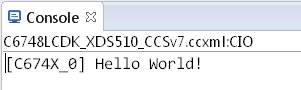
9.8. Gravity Simulator Demo
9.8.1. Overview
This demo showcases a simple video display with Processor SDK RTOS. This demo uses Gravit, a GPL-licensed open-sourced library, to simulate gravity of particles in space.
9.8.2. Version Details
Latest version: 1.0.0
Supported platforms: idkAM572x
Available in: Processor SDK RTOS 4.0.0.4
9.8.3. Components Used
Open Sourced Libraries:
- Gravit
RTOS Components:
- SYSBIOS
- XDC
Processor SDK RTOS Drivers:
- VPS
- PM
- I2C
- UART
- Board
- OSAL
- CSL
9.8.4. Building the Demo
The demo is available pre-built for Processor SDK RTOS version 4.0.0.4 or higher. You must first set up your development environment. Refer to the Processor SDK RTOS Building page for information on setting up your build environment.
The following are steps to clean the demo:
cd [SDK Install Path]/processor_sdk_rtos_[soc]_[version]/demos/gravit
make clean BOARD=idkAM572x
The following are steps to compile the demo:
cd [SDK Install Path]/processor_sdk_rtos_[soc]_[version]/demos/gravit
make BOARD=idkAM572x
9.8.5. Running the Demo
You will need the following:
- Code Composer Studio to load and run the demo. Refer to Processor SDK RTOS Getting Started Guide for installing CCS.
- idkAM572x board with attached LCD screen
- USB cable for JTAG and serial terminal (micro USB port)
To load and run the demo:
- Connect the USB cable from your computer to the idkAM572x’s JTAG port
- Power on the idkAM572x board. Ensure that no boot mode is entered (do not have SD card loaded or QSPI flashed)
- Open up a serial terminal for UART communication (Refer to Processor SDK RTOS Getting Started Guide, setup EVM hardware)
- Open CCS and launch target config file for idkAM572x (Refer to Processor SDK RTOS Setup CCS for setting up CCS)
- Connect to CortexA15_0
- Load and launch the demo executable:
[SDK Install Path]/processor_sdk_rtos_[soc]_[version]/demos/gravit/bin/idkAM572x/gravit_a15_0_release.xa15fg
9.8.6. Terminal Screenshot
- When launched, you will be prompt for number of particles to simulate. Enter a value up to 1000.
- Use w-a-s-d for display rotation
- Use i-j-k-l for display translation
- Press Esc to end current simulation and display accumulated statistics
- Frames per second (FPS) and floating point operations per second (FLOPS) are displayed on the terminal
Below is a screenshot of the terminal after one simulation:
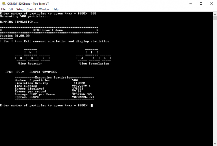
9.8.7. Display Output
- Particles are set to rotate around a gravity center positioned at the center of the LCD screen
- Particles are represented with 3D coordinates, projected to a 2D LCD screen. The projection is simplified such that the camera (or the viewer) does not change display angles.
Below is an example display of a 500-particle simulation:
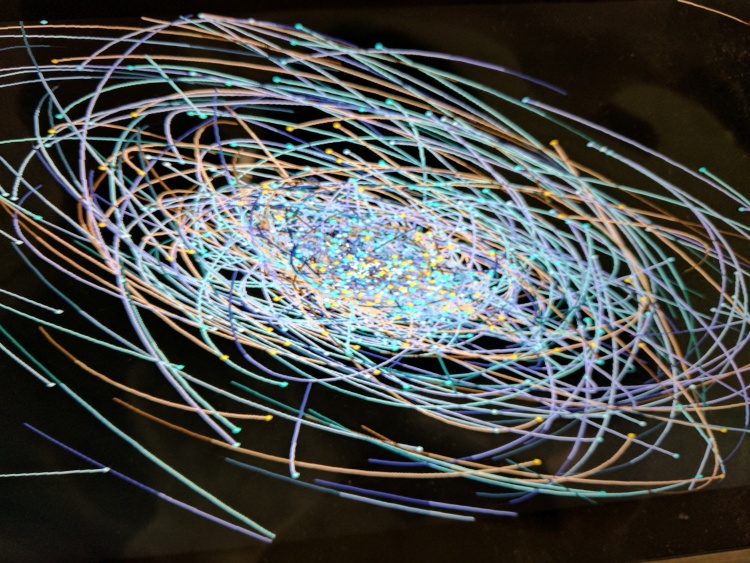
9.8.8. Useful References
Main Gravit website: https://gravit.slowchop.com/
Gravit github: https://github.com/gak/gravit
Physics algorithm behind gravit, Barnes-hut: https://en.wikipedia.org/wiki/Barnes-Hut_simulation
Bresenham’s line algorithm: https://en.wikipedia.org/wiki/Bresenham’s_line_algorithm
9.9. RTOS Template Application
9.9.1. Overview
The RTOS template application is intended for customers to use as a starting point during software development using Processor SDK RTOS software. The template application can be quickly brought up by importing the included CCS project into CCS development environment. The application currently includes the typical low level drivers (UART, GPIO, I2C), OSAL layer, and Board Library. For additional details refer to the README.txt file in the installed package.
9.9.2. Supported platforms
- evmAM65xx ( A53)
- evmAM572x
- evmAM335x
9.9.3. Requirements
Following are required to run the application:
Hardware
- TI EVM (see list above)
- Serial UART cable (provided in EVM kit)
Software
- Processor-SDK RTOS
- Code Composer Studio (CCS 8.0 and up for AM65xx)
9.9.4. Components Used
RTOS Components:
- SYS/BIOS
- XDCTools
- Processor SDK RTOS PDK: Drivers, OSAL, etc.
9.9.5. Software Design
The Template Application is designed to provide a foundation with clean separation of application specific sub-module. This allows users the ability to focus on application specific code and quickly get it to run. This is achieved by separating “main” and “app” sub modules in different files.
The source files are organized as follows:
└── template_app
    ├── main.c --> Main file including startup and init code
    ├── main.cfg --> Main BIOS config file
    ├── app.c  --> Application tasks are here
    ├── app.h  --> Application header file
    ├── app.cfg --> Application specific config file
    ├── app.defs --> Definitions (Currently empty)
    ├── rtos_template_app_<SOC>_<core>_<board>.projectspec --> Project spec file
In general to write a new application, app.c and app.h can be modified, recompiled, and run.
9.9.6. How to Build the Template Application
Please follow below step by step procedure to build the application.
- Processor SDK RTOS and Code Composer Studio.
- Install Processor SDK RTOS (AM65xx, AM57x, AM335x) respectively, in a location where CCS expects: (by default $HOME/ti or c:/ti) Refer Processor SDK RTOS Getting Started Guide for details.
- Open CCS:
- Click Project–>Import CCS Projects and select rtos_template_app under directory : <Processor_sdk_rtos_<platform>_<version>/demos/rtos_template_app/ (NOTE: This will create project under current workspace and also copy relevant files for the project.)
- Build the application . ( By right clicking on imported project and clicking “Build project”) (NOTE: This will create executable binary under rtos_template_app_<platform>/Debug/rtos_template_app_<platform>_<core>.out)
9.9.7. How to Run the Template Application
You will need the following:
- Install Code Composer Studio to load and run the Template Application. Refer to Processor SDK RTOS Getting Started Guide for installing CCS.
- evmAM65xx, evmAM572x or evm AM335x board
- JTAG Emulator
To load and run Template Application:
- Connect the computer to the JTAG port on the board using the JTAG emulator.
- Power on evmAM65xx, evmAM574x or evmAM335x board. Ensure that no boot mode is entered (do not have SD card loaded or QSPI flashed)
- Open up a serial terminal for UART communication (Refer to Processor SDK RTOS Getting Started Guide, setup EVM hardware)
- Open CCS and launch target config file for the EVM (Refer to Processor SDK RTOS Setup CCS for setting up CCS)
- Connect to the primary core to make sure on connect gels are run M3_0 first, then A53_0_0 for AM65xx; A15_0 core for AM572x ; A8 core for AM335x; CortexA9 on AM437X
- Connect to core where the application is expected to run, if not the primary core.
- Load executable by clicking(“Run –> Load –> Load Program.). Click on Browse Project and select outfile under: rtos_template_app_<platform><core>/Debug/rtos_template_app<platform>_<core>.out
- Run application by clicking the Run icon. ( Or Click Run –> Resume)
Now application will run and print progress through the UART.
- Press enter to get UART prompt.
uart_task :Enter a word or Esc to quit >
- Enter any word following by <CR>
The application will print back the entered word
- Enter [ESC-<CR>]
The application will exit.
9.9.8. Terminal Screenshot
Board Init complete
Uart Init complete
I2C Init complete
Gpio Init complete
MCSPI Init complete
======== Peripheral Initialization complete ========

======== Starting to create application tasks ========

    gpio_toggle_led_task task created.
    uart_task task created.
    spi_test_task task created.
    i2c_eeprom_read_and_display_task task created.
    ======== Application tasks created successfully ========

    gpio_toggle_led task started
    uart_task task started uart_task :Enter a word or Esc to quit >
    i2c_eeprom_read_and_display task started
    spi_test task started
    Board Name read: AM572PM_ (may be different for evmAM65xx)
    Board version read: A.3A  (may be different for evmAM65xx)
    spi_test task ended
    i2c_eeprom_read_and_display task ended
    uart_task :Enter a word or Esc to quit >
    uart_task :Enter a word or Esc to quit >testing
    Data received is:testing
    uart_task :Enter a word or Esc to quit >command
    Data received is:command
    uart_task :Enter a word or Esc to quit >^[
    uart_task task ended
    Template app ended
9.9.9. Porting to Custom Board
linkerBuildOptions=
" -L${TI_PDK_INSTALL_DIR}/packages/ti/board/lib/evmAM572x/a15/release/
  -l:ti.board.aa15fg
Note
Currently for AM572x there is also dependency on the GPIO_evmAM572x_board.c & GPIO_board.h. These files can be modified to customize for the customer board.