10. How to Guides
10.1. Target
10.1.1. Run IPC Examples on AM572x
10.1.1.1. DRA7xx/AM572xx IPC Examples
IPC Hello Example:
ex01_hello
The following examples demonstrate some of the rudimentary IPC capabilities. They are mostly two processors examples. These examples may be built for any two processors on your device, but only for two at a time. An IPC Ping example using three processors is also presented at the end.
Hello example uses the reader/writer design pattern. One processor will be the reader and the other will be the writer. The reader creates a message queue and waits on it for messages. The writer opens the reader’s message queue and sends messages to it. The writer allocates the message from a shared message pool and the reader returns the message to the pool. Thus, messages are sent in only one direction. Default settings of the Hello world example configures DSP1 as the writer and DSP2 as the reader.
Note
if Windows 7 machine is used for building these examples, GnuWin32 make utility needs to be installed to run make which can be downloaded from this link https://gnuwin32.sourceforge.net/packages/make.htm
Set GnuWin32\bin folder on file path and add a system variable XDCTOOLS_JAVA_HOME to point to “c:\ti\ccsv6\eclipse\jre“
set PATH=<YOUR_PROCEEDING_PATH>\GnuWin32\bin;%PATH%
set XDCTOOLS_JAVA_HOME=c:\ti\ccsv6\eclipse\jre
1. Change to the example folder by entering: cd ~/ti/ipc_nn_nn_nn_nn/examples/DRA7xx_bios_elf/ex01_hello
2. Open readme.txt file and follow build instructions step-by-step. If build this example on Ubuntu PC, make sure there is no spaces between variable name and its value.
DEPOT (your depository folder ex: DEPOT=/Your_Ubuntu_home_folder/ti)
BIOS_INSTALL_DIR=$(DEPOT)/bios_n_nn_nn_nn
IPC_INSTALL_DIR=$(DEPOT)/ipc_n_nn_nn_nn
XDC_INSTALL_DIR=$(DEPOT)/xdctools_n_nn_nn_nn
gnu.targets.arm.A15F=$(DEPOT)/ccsv6/tools/compiler/gcc-arm-none-eabi-4_8-2014q3
ti.targets.elf.C66=$(DEPOT)/ccsv6/tools/compiler/c6000_7.4.14
ti.targets.arm.elf.M4=$(DEPOT)/ccsv6/tools/compiler/arm_5.2.4
ti.targets.arp32.elf.ARP32_far=$(DEPOT)/ccsv6/tools/compiler/arm_5.2.4
See the following example, and ensure you are using the latest version
of folder names present in ~/ti folder:

DEPOT=/home/Your_Ubuntu_home_folder/ti

# Use the following environment assignment  (Note you must use 32 bit Java even in Ubuntu 14.04 64 bit OS environment)
export XDCTOOLS_JAVA_HOME=/home/Your_Ubuntu_home_folder/ti/ccsv6/eclipse/jre

#### BIOS-side dependencies ####
BIOS_INSTALL_DIR=$(DEPOT)/bios_6_41_04_54
IPC_INSTALL_DIR=$(DEPOT)/ipc_3_36_01_11
XDC_INSTALL_DIR=$(DEPOT)/xdctools_3_31_02_38

#### BIOS-side toolchains ####
gnu.targets.arm.A15F=$(DEPOT)/ccsv6/tools/compiler/gcc-arm-none-eabi-4_8-2014q3
ti.targets.elf.C66=$(DEPOT)/ti-cgt-c6000_8.0.3
ti.targets.arm.elf.M4=$(DEPOT)/ccsv6/tools/compiler/ti-cgt-arm_5.2.4
ti.targets.arp32.elf.ARP32_far=$(DEPOT)/ccsv6/tools/compiler/ti-cgt-arm_5.2.4
- Run make command in current folder to build DSP1 and DSP2 hello examples. Output files are created under debug sub folders.
- ex01_hello\dsp1\bin\debug
- ex01_hello\dsp2\bin\debug
- Launch target configurations.
- Right click CortexA15_0 and connect target.
- On CCS –> Scripts –> AM572 Multicore Initialization –> Run AM572x Multicore EnableAllCore
- Initialize DDR configuration. On CCS –> Scripts –> DDR configurations –> AM572_DDR3_532MHz_config
- Load DSP1 Hello Example hello_dsp1.xe66 (writer)file on DSP1.
- Load DSP2 Hello Example hello_dsp2.xe66 (reader) file on DSP2.
- Run both DSP1 and DSP2.
- On CCS –> Tools –> RTOS Object view (ROV).
- Suspend (halt) DSP1 to view test messages on ROV Viewable Modules –>LoggerBuf Refer below image of ROV log messages.
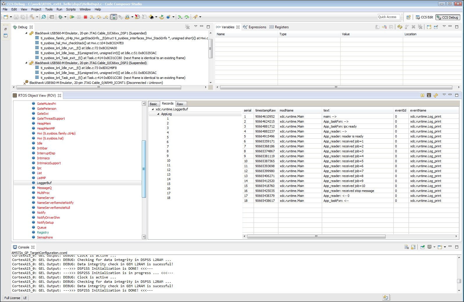
- Suspend (halt) DSP2 and click on ROV icon to view log messages.
IPC Message Queue Example:
ex02_messageq
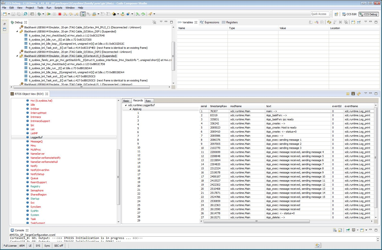
Message queue example sends round-trip message from client to server and back. MessageQ example uses client/server pattern. It is a two processors example: the HOST and DSP processors. Either DSP1 or DSP2 can be built for testing.
The DSP processor is configured as server. It creates a named message queue. The server does not open any queues because it extracts the return address from the message header. The server returns all messages to the sender. It does not access the message pool.
The HOST processor is configured as client application. The client creates an anonymous message queue. The client also creates and manages the message pool. The client’s return address is set in the message header for each message before sending it to the server.
- Change to messageQ folder example by enter: cd
~/ti/ipc_nn_nn_nn_nn/examples/DRA7xx_bios_elf/ex02_messageQ
2. Open readme.txt file and follow build instructions step-by-step. Make sure there is no spaces between variable name and its value. See Hello World example environment varaible settings for reference.
- Run make command in current folder to build DSP1 and HOST hello examples. Output files are created under debug sub folders
- ex02_messageq\host\bin\debug : HOST A15 binary
- ex02_messageq\dsp1\bin\debug : C66x binary
- Launch target configurations. Note that BH560USB_M is emulator is used to connect to AM572X EVM.
- Right click CortexA15_0 and connect target.
- On CCS –> Scripts –> AM572 Multicore Initialization –> Run AM572x Multicore EnableAllCore
- Initialize DDR configuration. On CCS –> Scripts –> DDR configurations –> AM572_DDR3_532MHz_config
- Load DSP1 messageQ Example out file(server_dsp1.xe66) onto DSP1.
- Load HOST messageQ Example out file(app_host.xa15fg) onto ARM CortexA15_0.
- Run both DSP1 and HOST.
- On CCS –> Tools –> RTOS Object view (ROV).
- Suspend (halt) ARM Cortex_A15 to view test messages on ROV Viewable Modules –>LoggerBuf Refer the following ROV message queue screenshot
- Suspend (halt) DSP1 and click on ROV icon to view log messages.
IPC Notify Peer Example:
ex13_notifypeer
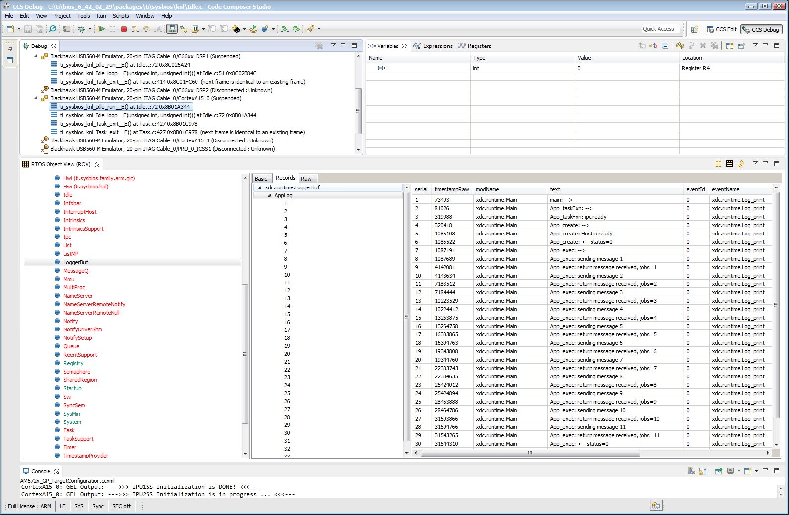
Notify peer example only uses notify to communicate to a peer processor. This is an example of IPC Scalability. It uses the client/server design pattern. Initially, the example builds only for two processors: HOST and DSP1. The client runs on HOST and the server runs on DSP1.
The client (HOST) creates an anonymous message queue. The client also creates and manages its own message pool. And it opens the server message queue using its name. The client initiates the data flow by allocating a message from the pool, placing its return address in the message header and sending the message to the server. It then waits for the message to be returned. When it receives the return message, the message is returned to the pool. The client repeats this in a loop.
The server (DSP1) creates a named message queue, then waits on it for messages. When a message arrives, the server performs the requested work. When the work is done, the server extracts the return address from the message header and sends the message back to the client. The server never opens any message queues and does not access the message pool.
Since DSP1 will need to wait on both the message queue and the notify queue, we introduce events. The SYS/BIOS event object can be used to wait on multiple input sources.
- Change to notify_peer folder example by enter: cd ~/ti/ipc_nn_nn_nn_nn/examples/DRA7xx_bios_elf/ex13_notifypeer
- Open readme.txt file and follow build instructions step-by-step. Make sure there is no spaces between variable name and its value.
- Run make command in current folder to build DSP1 and HOST notifypeer examples. Output files are created under debug subfolder.
- Launch target configurations. Note that BH560USB_M is emulator is used to connect to AM572X EVM.
- Right click CortexA15_0 and connect target.
- On CCS –> Scripts –> AM572 Multicore Initialization –> Run AM572x Multicore EnableAllCore
- Initialize DDR configuration. On CCS –> Scripts –> DDR configurations –> AM572_DDR3_532MHz_config
- Load DSP1 notifypeer Example out file on DSP1.
- Load HOST notifypeer Example out file on ARM CortexA15_0.
- Run both DSP1 and CortexA15_0.
- On CCS –> Tools –> RTOS Object view (ROV).
- Suspend (halt) ARM CortexA15_0 to view test messages on ROV Viewable Modules –>LoggerBuf. Refer the following image of ROV log messages
- Suspend (halt) DSP2 and click on ROV icon to view log messages.
IPC Ping Example:
ex11_ping
ping example sends a message between all cores in the system. This example is used to exercise every communication path between all processors in the system (including local delivery on the current processor). Ping example is also organized in a suitable manner to develop an application with different compute units on each processor.
Each executable will create two tasks: 1) the server task, and 2) the application task. The server task creates a message queue and then waits on that queue for incoming messages. When a message is received, the server task simply sends it back to the original sender.
The application task creates its own message queue and then opens every server message queue in the system (including the server queue on the local processor). The task sends a message to a server and waits for the message to be returned. This is repeated for each server in the system (including the local server).
Note
Note that presently EVE is not yet supported and therefore, DSP1/DSP2/HOST are built for testing.
1. Change to ping folder example by enter: cd ~/ti/ipc_nn_nn_nn_nn/examples/DRA7xx_bios_elf/ex11_ping
2. Open readme.txt file and follow build instructions step-by-step. Make sure there is no space between variable name and its value.
- Open makefile and remove EVE and IPU from PROC build list.
- Run make command in current folder to build DSP1, DSP2 and HOST ping examples. Output files are created under debug subfolder.
- Launch target configurations. Note that BH560USB_M is emulator is used to connect to AM572X EVM.
- Right click CortexA15_0 and connect target.
- On CCS –> Scripts –> AM572 Multicore Initialization –> Run AM572x Multicore EnableAllCore
- Initialize DDR configuration. On CCS –> Scripts –> DDR configurations –> AM572_DDR3_532MHz_config
- Load DSP1 Ping Example out file on DSP1.
- Load DSP2 Ping Example out file on DSP2.
- Load HOST ping Example onto ARM CortexA15_0
- Run DSP1, DSP2, and HOST images.
- On CCS –> Tools –> RTOS Object view (ROV).
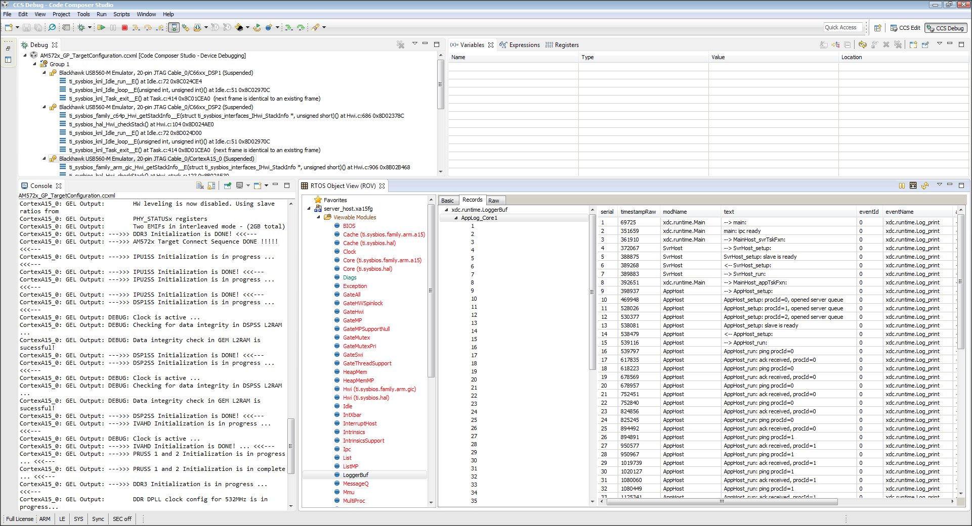
- Halt DSP1 to view test messages on ROV Viewable Modules –>LoggerBuf Refer below image of ROV log messages
- Suspend (halt) DSP2 and click on ROV icon to view log messages.
- Suspend (halt) ARM CortexA15_0 and click on ROV icon to view log messages.
Expanding IPC Ping Example:
To demonstrate the flexibility of IPC architecture, you may include additional cores to the above example by modifying the make file. For example, you may add IPU1 in the list of processor in the make file as: DSP1, DSP2, IPU1, HOST. After a clean build, the appropriate configuration and output executable files will be generated that allow passing messages between DSP1, DSP2, IPU1 and Host. Procedures are the same as described in the previous example with the exception of additional steps to load the IPU1 core with the corresponding executable and running it in conjunction with DSP1, DSP2 and HOST.
Note
During build process using IPU1, you may encounter a message indicating rtsv7M4_T_le_eabi.lib library is missing. This is a know issue and is being tracked by SDCOM00118417 IR. However, you may create this missing library by going to the compiler installation’s lib directory and execute the following command to regenerate all required libraries:
./mklib --all
The following example depicts a typical host communications protocol with other IPC apps (dsp1, dsp2, ipu1) Note that the following HOST communications list has been rearranged to further clarify the type of communications between various cores. Typically these messages arrive at different intervals depending on each core processes execution time.
1    xdc.runtime.Main    --> main:
2    xdc.runtime.Main    main: ipc ready
3    xdc.runtime.Main    MainHost_svrTskFxn:
4    SvrHost    --> SvrHost_setup:
5    SvrHost    SvrHost_setup: slave is ready
6    SvrHost    <-- SvrHost_setup:
7    SvrHost    --> SvrHost_run:
8    xdc.runtime.Main    --> MainHost_appTskFxn:
9    AppHost    --> AppHost_setup:

10    AppHost    AppHost_setup: procId=0     opened server queue
11    AppHost    AppHost_setup: procId=1     opened server queue
12    AppHost    AppHost_setup: procId=2     opened server queue
28    AppHost    AppHost_setup: procId=3     opened server queue

32    AppHost    AppHost_run: ping procId=0
34    AppHost    AppHost_run: ping procId=0
36    AppHost    AppHost_run: ping procId=0
38    AppHost    AppHost_run: ping procId=0
40    AppHost    AppHost_run: ping procId=0

33    AppHost    AppHost_run: ack received     procId=0
35    AppHost    AppHost_run: ack received     procId=0
37    AppHost    AppHost_run: ack received     procId=0
39    AppHost    AppHost_run: ack received     procId=0
41    AppHost    AppHost_run: ack received     procId=0

13    SvrHost    SvrHost_run: message received     procId=0
14    SvrHost    SvrHost_run: message received     procId=0
15    SvrHost    SvrHost_run: message received     procId=0
16    SvrHost    SvrHost_run: message received     procId=0
17    SvrHost    SvrHost_run: message received     procId=0

42    AppHost    AppHost_run: ping procId=1
44    AppHost    AppHost_run: ping procId=1
46    AppHost    AppHost_run: ping procId=1
48    AppHost    AppHost_run: ping procId=1
50    AppHost    AppHost_run: ping procId=1

43    AppHost    AppHost_run: ack received     procId=1
45    AppHost    AppHost_run: ack received     procId=1
47    AppHost    AppHost_run: ack received     procId=1
49    AppHost    AppHost_run: ack received     procId=1
51    AppHost    AppHost_run: ack received     procId=1

18    SvrHost    SvrHost_run: message received     procId=1
19    SvrHost    SvrHost_run: message received     procId=1
20    SvrHost    SvrHost_run: message received     procId=1
21    SvrHost    SvrHost_run: message received     procId=1
22    SvrHost    SvrHost_run: message received     procId=1

52    AppHost    AppHost_run: ping procId=2
55    AppHost    AppHost_run: ping procId=2
58    AppHost    AppHost_run: ping procId=2
61    AppHost    AppHost_run: ping procId=2
64    AppHost    AppHost_run: ping procId=2

54    AppHost    AppHost_run: ack received     procId=2
57    AppHost    AppHost_run: ack received     procId=2
60    AppHost    AppHost_run: ack received     procId=2
63    AppHost    AppHost_run: ack received     procId=2
66    AppHost    AppHost_run: ack received     procId=2

53    SvrHost    SvrHost_run: message received     procId=2
56    SvrHost    SvrHost_run: message received     procId=2
59    SvrHost    SvrHost_run: message received     procId=2
62    SvrHost    SvrHost_run: message received     procId=2
65    SvrHost    SvrHost_run: message received     procId=2

67    AppHost    AppHost_run: ping procId=3
69    AppHost    AppHost_run: ping procId=3
71    AppHost    AppHost_run: ping procId=3
73    AppHost    AppHost_run: ping procId=3
75    AppHost    AppHost_run: ping procId=3

68    AppHost    AppHost_run: ack received     procId=3
70    AppHost    AppHost_run: ack received     procId=3
72    AppHost    AppHost_run: ack received     procId=3
74    AppHost    AppHost_run: ack received     procId=3
76    AppHost    AppHost_run: ack received     procId=3

23    SvrHost    SvrHost_run: message received     procId=3
24    SvrHost    SvrHost_run: message received     procId=3
25    SvrHost    SvrHost_run: message received     procId=3
26    SvrHost    SvrHost_run: message received     procId=3
27    SvrHost    SvrHost_run: message received     procId=3

29    AppHost    AppHost_setup: slave is ready
30    AppHost    <-- AppHost_setup:
31    AppHost    --> AppHost_run:
77    AppHost    <-- AppHost_run: 0
78    AppHost    --> AppHost_destroy:
79    AppHost    <-- AppHost_destroy: status=0
80    xdc.runtime.Main    <-- MainHost_appTskFxn: 0
81    xdc.runtime.Main    MainHost_done:
10.1.2. Taking the C66x Out Of Reset with Linux Running on the ARM A15
10.1.2.1. How to take the C66x DSP out of reset with Linux running on A15
This document describes the procedure to bring the C66x core out of reset after booting Linux, or at the u-boot prompt.These steps are necessary in to order to load an application on the C66x core, without interfering with the operation of Linux running on the A15.
Note
Prior to proceeding with the below instructions, please ensure that the latest Emulation Package is downloaded/installed through CCS. This will ensure the GEL files in your machine has the reset routines described below.
- Once Linux has booted, launch the target configuration.
- With the target configuration launched, right click on K2x.ccxml and select “Show all cores”
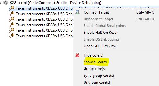
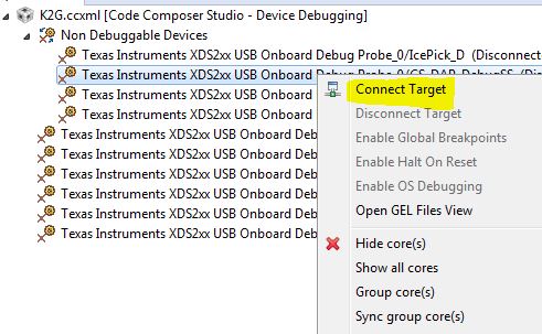
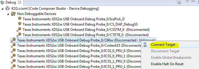
- This will bring up the Non-Debuggable Devices section. Right click and connect the CS_DAP_Debug_SS core.
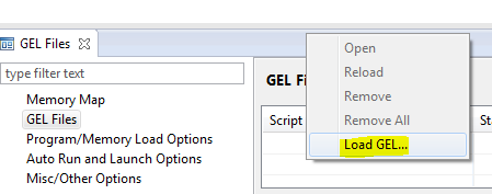
- Go to Tools>GEL files and load the evmk2x.gel file by right clicking on the GEL file window. The Gel file would typically be located in the CCS installation under \ccsv6\ccs_base\emulation\boards\evmk2x\gel\
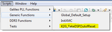
- Once the GEL has been successfully loaded, go to Scripts>default and select K2x_TakeDSPOutofReset.
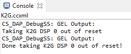
- At this point the console would indicate that the DSP is out of reset.
- Now the DSP cores can be right-clicked and connected successfully.
10.1.2.2. Target Configuration
Note
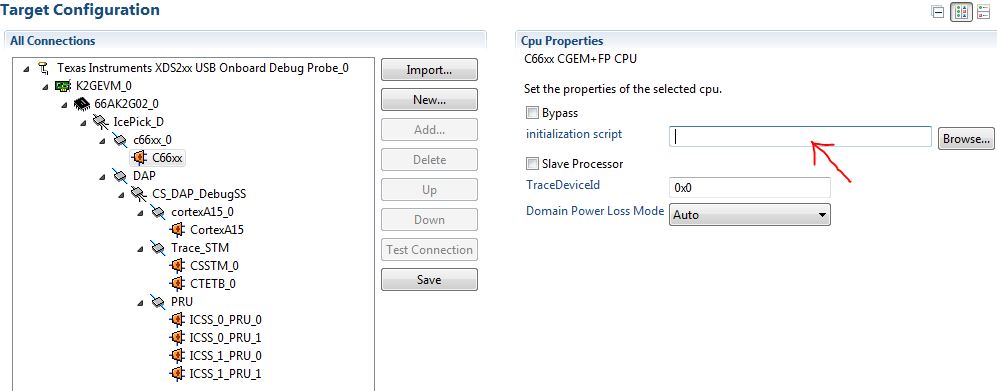
Once the DSP core is connected following the above out of reset routine, the DDR and PLL settings done by u-boot would be overwritten by what’s in the GEL. In order to avoid this, please ensure that the gel is NOT preloaded on the DSP core in the ccxml by leaving the initialization script blank.
10.2. Host
10.2.1. Setup
10.2.1.1. Setup CCS for EVM and Processor-SDK RTOS
Overview
This page provides information on configuring CCS to work with both the EVM and the Processor-SDK for RTOS.
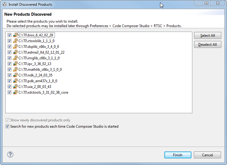
Discovering SDK products
CCS and SDK installed in same directory
After installing the Processor-SDK RTOS, start CCS and it will automatically detect the newly installed components (products):
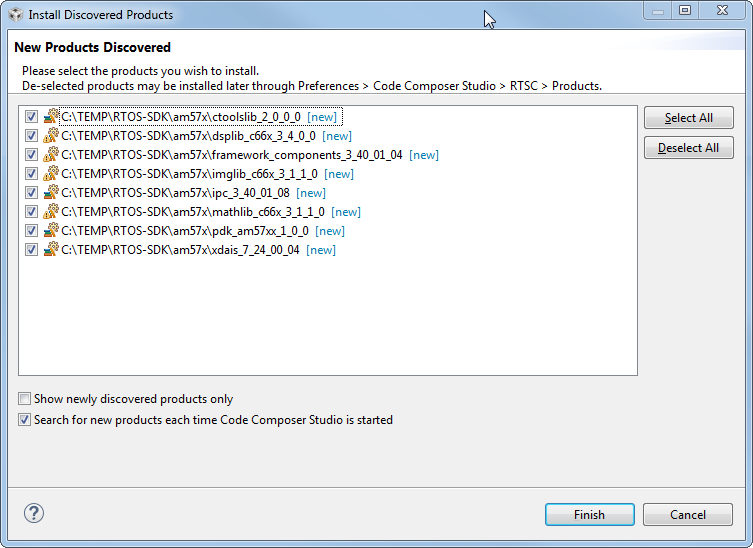
CCS and SDK installed in different directories
If you chose to install the SDK package in a different folder from where CCS is installed (e.g. C:\TEMP\RTOS-SDK\am57x), then you will need to add the path to the search path for CCS to locate the new packages. The screenshots below demonstrate the process to setup the CCS environment; the sequence for a Linux host is the same.
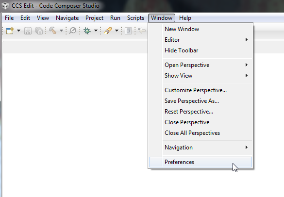
Go to product preference
From CCS, select “Window -> Preferences”:
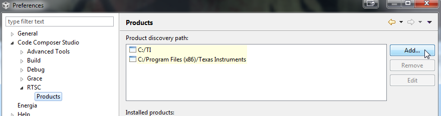
Enter path to SDK
In the Preferences window, select “Code Composer Studio -> RTSC -> Products” in the panel on the left. Then, press the “Add” button on the panel on the right:
Verify components
Next, verify the newly discovered products. If everything is correct, press the “Finish” button on the bottom:
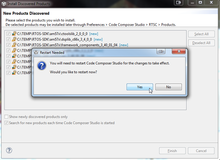
Restart CCS
When prompted, restart CCS for changes to take effect. You will see newly discovered products from the custom path.
Create Target Configuration File for EVM
In CCS, you need to create a Target Configuration for your EVM to be able to connect to the target. This configuration defines your:
- Connection to the target (XDS, FET, etc.)
- Target device (AM437x GP EVM, AM57x GP EVM, etc.)
- GEL file for hardware initialization. A GEL file is basically a “batch file” that sets up the CCS debug environment including memory map, PLL, clock, etc.
CCS comes with basic configuration that can be used to configure your particular setup. In the example below, we provide details for a GP AM437x EVM; configuration information for other supported EVMs are also provided as needed.
For EVM specific instructions, refer to the Hardware User’s Guide for your EVM
Note
Note for K2G devices: If using CCS v6.1.2 and Keystone2 device support v1.1.7, 66AK2G02 would not show up in the list of devices when creating the target configuration. This is due to an incompatibility in the XML parser in CCS v6.1.2 with the K2G device xml. In order to work-around this issue, make the change in 66AK2G02.xml as illustrated below in order to have 66AK2G02 display in the device list. This problem does not exist in CCS v6.1.3 onwards as the XML parser has been updated.
C:\ti\ccsv6\ccs_base\common\targetdb\devices\66AK2G02.xml

Line #1

<?xml version="1.1" encoding="UTF-8" standalone="no"?>
to
<?xml version="1.0" encoding="UTF-8" standalone="no"?>
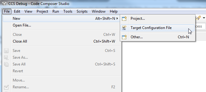
Open new target configuration file
From CCS, select “File -> New -> Target Configuration File”:
Select target configuration options
The AM437x GP EVM supports embedded XDS100V2 USB Emulation through the MicroUSB AB connector. Select
- Connection: Texas Instruments XDS100v2 USB Debug Probe
- Board or Device: EVMAM437X
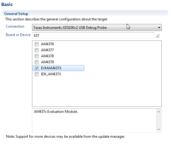
Useful Tip
If you enter the starting numbers of your device in the Board or Device field, the list will show the relevant subset.
Here is a table showing configuration information for all supported EVMs in the Processor-SDK RTOS:
| EVM | Connection | Board |
|---|---|---|
| GP335x | External Emulator Supplied by User. EVM includes a TI 20 pin JTAG connector. | EVMAM3358 |
| ICE335x | Texas Instruments XDS100v2 USB Debug Probe | ICE_AM3359 |
| SK335x | Texas Instruments XDS100v2 USB Debug Probe | SK_AM3358 |
| BBB | External Emulator Supplied by User. EVM includes a TI 20 pin JTAG connector. | BeagleBone_Black |
| GP437x | Texas Instruments XDS100v2 USB Debug Probe | EVMAM437X |
| IDK437x | Texas Instruments XDS100v2 USB Debug Probe | IDK_AM437X |
| GP572x | External Emulator Supplied by User. EVM includes a TI 20 pin JTAG connector. | GPEVM_AM572X |
| X15 | External Emulator Supplied by User. EVM includes a TI 20 pin JTAG connector. | GPEVM_AM572X |
| IDK572x/IDK574x | Texas Instruments XDS100V2 USB Debug Probe External Emulator Supplied by User. EVM includes a 60-pin MIPI JTAG connector | IDK_AM572X/IDK_AM574X |
| C665x EVM | Texas Instruments XDS2xx USB Onboard Debug Probe | TMS320C6657 |
| C667x EVM | L w/ XDC100: Texas Instruments XDS100v1 USB Emulator LE/LXE with XDS560: Blackhawk XDS560v2-USB Mezzanine Emulator | TMS320C6678 |
| K2E EVM | Texas Instruments XDS2xx USB Onboard Debug Probe | 66AK2E05 |
| K2H EVM | Texas Instruments XDS2xx USB Onboard Debug Probe | 66AK2H12 |
| K2L EVM | Texas Instruments XDS2xx USB Onboard Debug Probe | TCI6630K2L |
| K2G GP EVM | Texas Instruments XDS2xx USB Onboard Debug Probe | 66AK2G02 |
| OMAPL137 EVM | Spectrum Digital XDS510USB Emulator | OMAPL137SK |
| OMAPL138 LCDK | External Emulator Supplied by User. EVM includes a TI 14 pin JTAG connector. | OMAPL138LCDK |
Save target configuration
Next, save the target configuration by pressing the Save button:
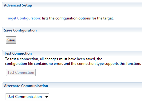
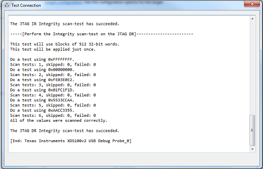
Test target configuration
Next, test the target configuration by pressing the Test Connection button. This will confirm that you have successfully created an emulator connection with your board.
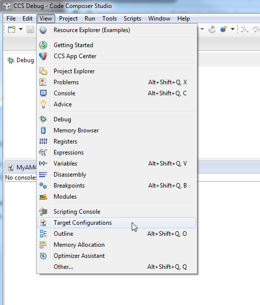
View target configurations
From CCS, select “View -> Target Configurations”:
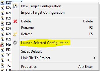
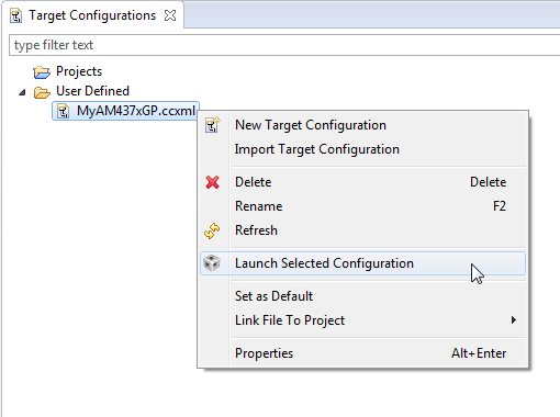
Launch target configuration
Open “User Defined” list and right click on the target configuration file that was just saved and select “Launch Selected Configuration”:
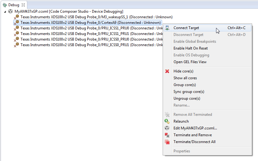
Connect target
After launch, you can connect to a core. For GP AM437x EVM, select Cortex A9 and select “Connect Target”:
Success!
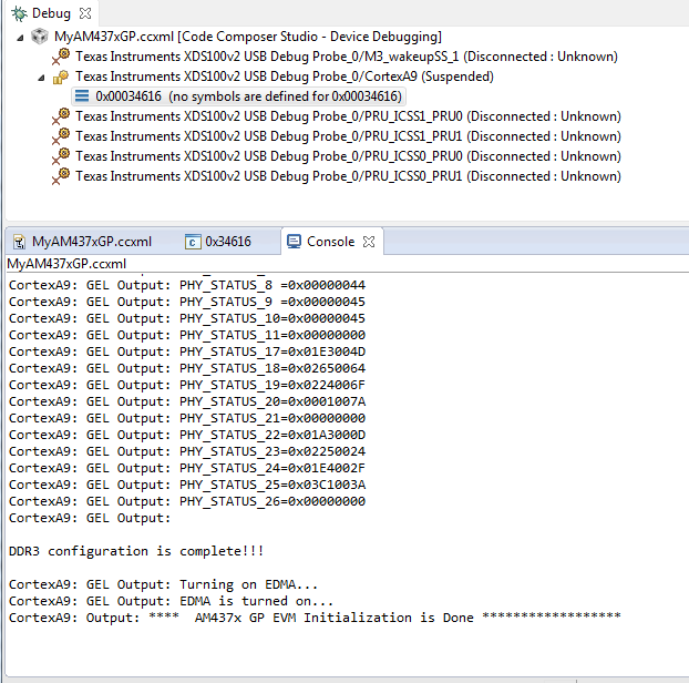
After connecting to target, check the console for status. Typically, the end of the configuration will indicate success or failure. For GP AM437x EVM, you will see the message “AM437x GP EVM Initialization is Done”:
Additional Notes for AM57x
Connect to Slave Cores
After connecting to the boot master core – typically the ARM core – you may need to connect to a slave core in order to run code. Depending on your SOC, the slave core can be
- DSP C66x
- ARM M4
- PRUSS
- IVAHD
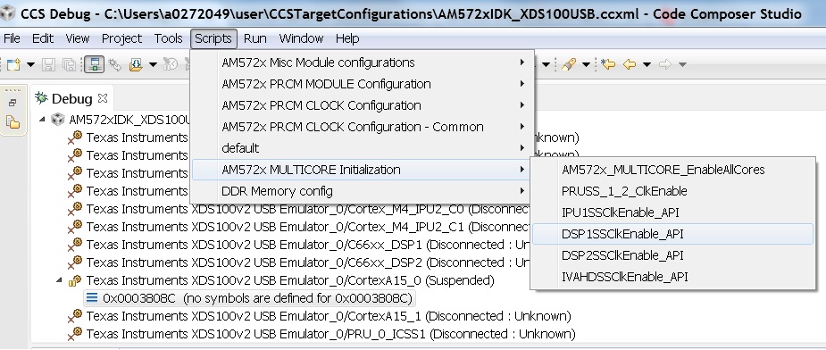
Typically the slave cores will wait in reset state until the master core wakes up the slave core to run code. To connect to the slave core on AM57x, go to Scripts menu in CCS Debug View and under AM572x MULTICORE Initialization enable the corresponding sub system clock. For example, enable DSP11SSClkEnable_API for the first DSP core. After running the clock enable option, you can connect to the core.
Timer Suspend Control Options for DSP
On AM57xx devices, all the timers on the chip have their suspend control signal routed to the A15 core. Which means that if any of the slave cores are using these timers, the timers will continue to run even when the slave core has been paused. The timer will only pause when the A15 core is halted.
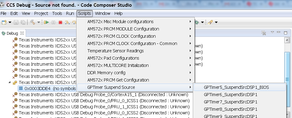
This is confusing while debugging code on slave cores if you are relying on timer for logging, inserting delays or if the timer keeps firing interrupts even when the core is halted. One such scenario occurs with GPtimer5 when DSP developers are using SYS/BIOS. The OS uses GPtimer5 on the DSP and forces a frequency check to confirm the timer configuration, however the OS can’t gain access to the timer due to the hook up of the suspend control signals.
Due to this issue the SYS/BIOS developers will need to configure an additional CCS configuration check to connect the GPTimer suspend control signal to the DSP as shown in the image below:
Troubleshooting
If you face any problems, first check these basic items:
- Power cycle your target.
- Check the USB cable. One simple way to do this is to connect another device to the USB and ensure the cable works.
- Check host driver. Even with CCS turned off, your host should list the TI XDS as a USB device. If this does not work, try a different USB port.
- Latest emulation package. Ensure that you have the latest emulation files as specified in the Getting Started Guide.
If this does not resolve your problem, see these additional resources:
10.2.1.2. Update environment when installing to a custom path
Overview
This page will provide configuration information if the SDK is installed in a custom path.
Useful Tip To avoid changing environment variable for each new shell, modify environment variable file directly. This file is the setupenv file located in the SDK root directory.
Changes to CCS Configuration
Installing the SDK in a folder other than where CCS is installed will require modifications to CCS to be able to discover the SDK. See the Setup CCS How To page explaining how to update CCS configuration.
Rebuilding the SDK RTOS
Installing the SDK in a folder other than the default (C:\TI for Windows, /home/[user]/ti for Linux) requires modifications to SDK RTOS scripts in order for recompilation and example/test creation to work properly.
In all the commands below, replace [version] with the appropriate version of the software/tool.
CCS in Custom Path and SDK RTOS in Default Path
CCS installation and toolchain paths can be customized by setting the TOOLS_INSTALL_PATH environment variable prior to running the SDK level setupenv script. This feature is used if CCS and the toolchains are installed somewhere other than the default C:\ti location.
For example, environment configuration assuming CCS is installed to [os_base]\ti_temp and SDK RTOS has been installed to default path, [os_base]\ti :
- Windows
C:\> set TOOLS_INSTALL_PATH=C:\ti_temp
C:\> cd C:\ti\processor_sdk_rtos_[soc]_[version]
C:\ti\processor_sdk_rtos_[soc]_[version]> setupenv.bat
Gives the output:
Optional parameter not configured : CG_XML_BIN_INSTALL_PATH
REQUIRED for xdc release build
Example: set CG_XML_BIN_INSTALL_PATH=C:/ti/cg_xml/bin
Optional parameter not configured : DOXYGEN_INSTALL_PATH
REQUIRED for xdc release build
Example: set DOXYGEN_INSTALL_PATH=C:/ti/Doxygen/doxygen/1.5.1-p1/bin
**************************************************************************
Environment Configuration:
    PDK Directory             : /ti/PDK_AM~3/packages/
    CGTOOL INSTALL Directory  : C:/ti_temp/ccsv6/tools/compiler/ti-cgt-c6000_[version]
    TOOLCHAIN A15 Directory   : C:/ti_temp/ccsv6/tools/compiler/gcc-arm-none-eabi-[version]
    TOOLCHAIN A8 Directory    : C:/ti_temp/ccsv6/tools/compiler/gcc-arm-none-eabi-[version]
    TOOLCHAIN A9 Directory    : C:/ti_temp/ccsv6/tools/compiler/gcc-arm-none-eabi-[version]
    TOOLCHAIN M4 Directory    : C:/ti_temp/ccsv6/tools/compiler/ti-cgt-arm_[version]
    FPULIB_PATH               : C:/ti_temp/ccsv6/tools/compiler/gcc-arm-none-eabi-[version]/lib/gcc/arm-none-eabi/[version]/fpu
    CROSS_TOOL_PRFX           : arm-none-eabi-
    XDC_INSTALL_PATH          : C:/ti/xdctools_[version]_core
    BIOS_INSTALL_PATH         : C:/ti/bios_[version]
    IPC_INSTALL_PATH          : C:/ti/ipc_[version]
    EDMA3LLD_BIOS6_INSTALLDIR : C:/ti/edma3_lld_[version]
    NDK_INSTALL_PATH          : C:/ti/ndk_[version]
    IMGLIB_INSTALL_PATH       : C:/ti/imglib_c66x_[version]
    UIA_INSTALL_PATH          : C:/ti/uia_[version]
    PROC_SDK_INSTALL_PATH     : C:/ti/processor_sdk_rtos_[soc]_[version]
**************************************************************************
Changing to short name to support directory names containing spaces
current directory: C:/ti/processor_sdk_rtos_[soc]_[version]
PROCESSOR SDK BUILD ENVIRONMENT CONFIGURED
**************************************************************************
- Linux
$ export TOOLS_INSTALL_PATH=~/ti_temp
$ cd ~/ti/processor_sdk_rtos_[soc]_[version]/
~/ti/processor_sdk_rtos_[soc]_[version]$ source setupenv.sh
Gives the output:
Optional parameter not configured : CG_XML_BIN_INSTALL_PATH
REQUIRED for xdc release build
Example: export CG_XML_BIN_INSTALL_PATH="~/ti/cg_xml/bin"
Optional parameter not configured : DOXYGEN_INSTALL_PATH
REQUIRED for xdc release build
Example: export DOXYGEN_INSTALL_PATH="~/ti/Doxygen/doxygen/1.5.1-p1/bin"
**************************************************************************
Environment Configuration:
    PDK Directory             : /home/[user]/ti/pdk_[soc]_[version]/packages
    CGTOOL INSTALL Directory  : /home/[user]/ti_temp/ccsv6/tools/compiler/ti-cgt-c6000_[version]
    TOOLCHAIN A15 Directory   : /home/[user]/ti_temp/ccsv6/tools/compiler/gcc-arm-none-eabi-[version]
    TOOLCHAIN A8 Directory    : /home/[user]/ti_temp/ccsv6/tools/compiler/gcc-arm-none-eabi-[version]
    TOOLCHAIN A9 Directory    : /home/[user]/ti_temp/ccsv6/tools/compiler/gcc-arm-none-eabi-[version]
    TOOLCHAIN M4 Directory    : /home/[user]/ti_temp/ccsv6/tools/compiler/ti-cgt-arm_[version]
    FPULIB_PATH               : /home/[user]/ti_temp/ccsv6/tools/compiler/gcc-arm-none-eabi-[version]/lib/gcc/arm-none-eabi/[version]/fpu
    CROSS_TOOL_PRFX           : arm-none-eabi-
    XDC_INSTALL_PATH          : /home/[user]/ti/xdctools_[version]_core
    BIOS_INSTALL_PATH         : /home/[user]/ti/bios_[version]
    IPC_INSTALL_PATH          : /home/[user]/ti/ipc_[version]
    EDMA3LLD_BIOS6_INSTALLDIR : /home/[user]/ti/edma3_lld_[version]
    NDK_INSTALL_PATH          : /home/[user]/ti/ndk_[version]
    IMGLIB_INSTALL_PATH       : /home/[user]/ti/imglib_c66x_[version]
    UIA_INSTALL_PATH          : /home/[user]/ti/uia_[version]
    PROC_SDK_INSTALL_PATH     : /home/[user]/ti/processor_sdk_rtos_[soc]_[version]

PROCESSOR SDK BUILD ENVIRONMENT CONFIGURED
*******************************************************************************
The RTOS SDK top level Makefile can now be used to rebuild SDK RTOS components with CCS and toolchains installed in a custom installation path.
CCS in Default Path and SDK RTOS in Custom Path
SDK RTOS component installation paths can be customized by setting the SDK_INSTALL_PATH variable prior to running the SDK level setupenv script. This feature is used if the SDK is installed somewhere other than the default C:\ti location.
For example, environment configuration assuming CCS is installed to the default path, [os_base]\ti and SDK RTOS has been installed to [os_base]\ti_temp:
- Windows
C:\> set SDK_INSTALL_PATH=C:/ti_temp
C:\> cd C:\ti_temp\processor_sdk_rtos_[soc]_[version]
C:\ti_temp\processor_sdk_rtos_[soc]_[version]> setupenv.bat
Gives the output:
Optional parameter not configured : CG_XML_BIN_INSTALL_PATH
REQUIRED for xdc release build
Example: set CG_XML_BIN_INSTALL_PATH=C:/ti/cg_xml/bin
Optional parameter not configured : DOXYGEN_INSTALL_PATH
REQUIRED for xdc release build
Example: set DOXYGEN_INSTALL_PATH=C:/ti/Doxygen/doxygen/1.5.1-p1/bin
**************************************************************************
Environment Configuration:
    PDK Directory             : /ti_temp/PDK_AM~3/packages/
    CGTOOL INSTALL Directory  : C:/ti/ccsv6/tools/compiler/ti-cgt-c6000_[version]
    TOOLCHAIN A15 Directory   : C:/ti/ccsv6/tools/compiler/gcc-arm-none-eabi-[version]
    TOOLCHAIN A8 Directory    : C:/ti/ccsv6/tools/compiler/gcc-arm-none-eabi-[version]
    TOOLCHAIN A9 Directory    : C:/ti/ccsv6/tools/compiler/gcc-arm-none-eabi-[version]
    TOOLCHAIN M4 Directory    : C:/ti/ccsv6/tools/compiler/ti-cgt-arm_[version]
    FPULIB_PATH               : C:/ti/ccsv6/tools/compiler/gcc-arm-none-eabi-[version]/lib/gcc/arm-none-eabi/[version]/fpu
    CROSS_TOOL_PRFX           : arm-none-eabi-
    XDC_INSTALL_PATH          : C:/ti_temp/xdctools_[version]_core
    BIOS_INSTALL_PATH         : C:/ti_temp/bios_[version]
    IPC_INSTALL_PATH          : C:/ti_temp/ipc_[version]
    EDMA3LLD_BIOS6_INSTALLDIR : C:/ti_temp/edma3_lld_[version]
    NDK_INSTALL_PATH          : C:/ti_temp/ndk_[version]
    IMGLIB_INSTALL_PATH       : C:/ti_temp/imglib_c66x_[version]
    UIA_INSTALL_PATH          : C:/ti_temp/uia_[version]
    PROC_SDK_INSTALL_PATH     : C:/ti_temp/processor_sdk_rtos_[soc]_[version]
**************************************************************************
Changing to short name to support directory names containing spaces
current directory: C:/ti_temp/processor_sdk_rtos_[soc]_[version]
PROCESSOR SDK BUILD ENVIRONMENT CONFIGURED
**************************************************************************
- Linux
$ export SDK_INSTALL_PATH=~/ti_temp
$ cd ~/ti_temp/processor_sdk_rtos_[soc]_[version]/
~/ti_temp/processor_sdk_rtos_[soc]_[version]$ source setupenv.sh
Gives the output:
Optional parameter not configured : CG_XML_BIN_INSTALL_PATH
REQUIRED for xdc release build
Example: export CG_XML_BIN_INSTALL_PATH="~/ti/cg_xml/bin"
Optional parameter not configured : DOXYGEN_INSTALL_PATH
REQUIRED for xdc release build
Example: export DOXYGEN_INSTALL_PATH="~/ti/Doxygen/doxygen/1.5.1-p1/bin"
**************************************************************************
Environment Configuration:
    PDK Directory             : /home/[user]/ti_temp/pdk_[soc]_[version]/packages
    CGTOOL INSTALL Directory  : /home/[user]/ti/ccsv6/tools/compiler/ti-cgt-c6000_[version]
    TOOLCHAIN A15 Directory   : /home/[user]/ti/ccsv6/tools/compiler/gcc-arm-none-eabi-[version]
    TOOLCHAIN A8 Directory    : /home/[user]/ti/ccsv6/tools/compiler/gcc-arm-none-eabi-[version]
    TOOLCHAIN A9 Directory    : /home/[user]/ti/ccsv6/tools/compiler/gcc-arm-none-eabi-[version]
    TOOLCHAIN M4 Directory    : /home/[user]/ti/ccsv6/tools/compiler/ti-cgt-arm_[version]
    FPULIB_PATH               : /home/[user]/ti/ccsv6/tools/compiler/gcc-arm-none-eabi-[version]/lib/gcc/arm-none-eabi/[version]/fpu
    CROSS_TOOL_PRFX           : arm-none-eabi-
    XDC_INSTALL_PATH          : /home/[user]/ti_temp/xdctools_[version]_core
    BIOS_INSTALL_PATH         : /home/[user]/ti_temp/bios_[version]
    IPC_INSTALL_PATH          : /home/[user]/ti_temp/ipc_[version]
    EDMA3LLD_BIOS6_INSTALLDIR : /home/[user]/ti_temp/edma3_lld_[version]
    NDK_INSTALL_PATH          : /home/[user]/ti_temp/ndk_[version]
    IMGLIB_INSTALL_PATH       : /home/[user]/ti_temp/imglib_c66x_[version]
    UIA_INSTALL_PATH          : /home/[user]/ti_temp/uia_[version]
    PROC_SDK_INSTALL_PATH     : /home/[user]/ti_temp/processor_sdk_rtos_[soc]_[version]

PROCESSOR SDK BUILD ENVIRONMENT CONFIGURED
*******************************************************************************
The RTOS SDK top level Makefile can now be used to rebuild SDK RTOS components installed in the custom installation path.
Note
The following known issue impacts this step: PRSDK-1263: PDK AM437x: Make fails on Windows if CCS is installed in custom path. Workaround: Edit the UTILS_INSTALL_DIR variable in <pdk_root_dir>/packages/ti/starterware/Rules.make to point to the CCS installation on your Windows PC.
CCS and SDK RTOS in Custom Path
When CCS and the SDK RTOS are both installed to custom paths the SDK can be rebuilt by setting the SDK_INSTALL_PATH and TOOLS_INSTALL_PATH variables prior to running the SDK RTOS top level environment setup script. The Windows and Linux environment setup scripts can be found in the following locations, respectively:
- Windows - C:\custom\install\path\processor_sdk_rtos_[soc]_[version]\setupenv.bat
- Linux - /home/[user]/custom/install/path/processor_sdk_rtos_[soc]_[version]/setupenv.sh
The SDK_INSTALL_PATH and TOOLS_INSTALL_PATH environment variables must be set to the custom install path prior to running the environment setup script.
For example, environment configuration assuming CCS and the SDK have been installed to [os_base]\new_sdk_release\ :
- Windows
C:\> set SDK_INSTALL_PATH=C:\new_sdk_release
C:\> set TOOLS_INSTALL_PATH=C:\new_sdk_release
C:\> cd C:\new_sdk_release\processor_sdk_rtos_[soc]_[version]
C:\new_sdk_release\processor_sdk_rtos_[soc]_[version]> setupenv.bat
Gives the output:
Optional parameter not configured : CG_XML_BIN_INSTALL_PATH
REQUIRED for xdc release build
Example: set CG_XML_BIN_INSTALL_PATH=C:/ti/cg_xml/bin
Optional parameter not configured : DOXYGEN_INSTALL_PATH
REQUIRED for xdc release build
Example: set DOXYGEN_INSTALL_PATH=C:/ti/Doxygen/doxygen/1.5.1-p1/bin
**************************************************************************
Environment Configuration:
    PDK Directory             : /NEW_SD~1/PDK_AM~1/packages/
    CGTOOL INSTALL Directory  : C:/new_sdk_release/ccsv6/tools/compiler/ti-cgt-c6000_[version]
    TOOLCHAIN A15 Directory   : C:/new_sdk_release/ccsv6/tools/compiler/gcc-arm-none-eabi-[version]
    TOOLCHAIN A8 Directory    : C:/new_sdk_release/ccsv6/tools/compiler/gcc-arm-none-eabi-[version]
    TOOLCHAIN A9 Directory    : C:/new_sdk_release/ccsv6/tools/compiler/gcc-arm-none-eabi-[version]
    TOOLCHAIN M4 Directory    : C:/new_sdk_release/ccsv6/tools/compiler/ti-cgt-arm_[version]
    FPULIB_PATH               : C:/new_sdk_release/ccsv6/tools/compiler/gcc-arm-none-eabi-[version]/lib/gcc/arm-none-eabi/[version]/fpu
    CROSS_TOOL_PRFX           : arm-none-eabi-
    XDC_INSTALL_PATH          : C:/new_sdk_release/xdctools_[version]_core
    BIOS_INSTALL_PATH         : C:/new_sdk_release/bios_[version]
    IPC_INSTALL_PATH          : C:/new_sdk_release/ipc_[version]
    EDMA3LLD_BIOS6_INSTALLDIR : C:/new_sdk_release/edma3_lld_[version]
    NDK_INSTALL_PATH          : C:/new_sdk_release/ndk_[version]
    IMGLIB_INSTALL_PATH       : C:/new_sdk_release/imglib_c66x_[version]
    UIA_INSTALL_PATH          : C:/new_sdk_release/uia_[version]
    PROC_SDK_INSTALL_PATH     : C:/new_sdk_release/processor_sdk_rtos_[soc]_[version]
**************************************************************************
Changing to short name to support directory names containing spaces
current directory: C:/new_sdk_release/processor_sdk_rtos_[soc]_[version]
PROCESSOR SDK BUILD ENVIRONMENT CONFIGURED
**************************************************************************
- Linux
$ export SDK_INSTALL_PATH=~/new_sdk_release
$ export TOOLS_INSTALL_PATH=~/new_sdk_release
$ cd ~/new_sdk_release/processor_sdk_rtos_[soc]_[version]/
~/new_sdk_release/processor_sdk_rtos_[soc]_[version]$ source setupenv.sh
Gives the output:
Optional parameter not configured : CG_XML_BIN_INSTALL_PATH
REQUIRED for xdc release build
Example: export CG_XML_BIN_INSTALL_PATH="~/ti/cg_xml/bin"
Optional parameter not configured : DOXYGEN_INSTALL_PATH
REQUIRED for xdc release build
Example: export DOXYGEN_INSTALL_PATH="~/ti/Doxygen/doxygen/1.5.1-p1/bin"
**************************************************************************
Environment Configuration:
    PDK Directory             : /home/[user]/new_sdk_release/pdk_[soc]_[version]/packages
    CGTOOL INSTALL Directory  : /home/[user]/new_sdk_release/ccsv6/tools/compiler/ti-cgt-c6000_[version]
    TOOLCHAIN A15 Directory   : /home/[user]/new_sdk_release/ccsv6/tools/compiler/gcc-arm-none-eabi-[version]
    TOOLCHAIN A8 Directory    : /home/[user]/new_sdk_release/ccsv6/tools/compiler/gcc-arm-none-eabi-[version]
    TOOLCHAIN A9 Directory    : /home/[user]/new_sdk_release/ccsv6/tools/compiler/gcc-arm-none-eabi-[version]
    TOOLCHAIN M4 Directory    : /home/[user]/new_sdk_release/ccsv6/tools/compiler/ti-cgt-arm_[version]
    FPULIB_PATH               : /home/[user]/new_sdk_release/ccsv6/tools/compiler/gcc-arm-none-eabi-[version]/lib/gcc/arm-none-eabi/[version]/fpu
    CROSS_TOOL_PRFX           : arm-none-eabi-
    XDC_INSTALL_PATH          : /home/[user]/new_sdk_release/xdctools_[version]_core
    BIOS_INSTALL_PATH         : /home/[user]/new_sdk_release/bios_[version]
    IPC_INSTALL_PATH          : /home/[user]/new_sdk_release/ipc_[version]
    EDMA3LLD_BIOS6_INSTALLDIR : /home/[user]/new_sdk_release/edma3_lld_[version]
    NDK_INSTALL_PATH          : /home/[user]/new_sdk_release/ndk_[version]
    IMGLIB_INSTALL_PATH       : /home/[user]/new_sdk_release/imglib_c66x_[version]
    UIA_INSTALL_PATH          : /home/[user]/new_sdk_release/uia_[version]
    PROC_SDK_INSTALL_PATH     : /home/[user]/new_sdk_release/processor_sdk_rtos_[soc]_[version]

PROCESSOR SDK BUILD ENVIRONMENT CONFIGURED
*******************************************************************************
The RTOS SDK top level Makefile can now be used to rebuild SDK RTOS components installed in the custom installation path using CCS and toolchains installed in a custom path as well.
Rebuilding the PDK
Installing the PDK in a folder other than the default (C:TI for Windows, /home/[user]/ti for Linux) requires modifications to PDK scripts in order for recompilation and example/test creation to work properly.
CCS in Custom Path and PDK in Default Path
The instructions provided in the CCS in Custom Path and SDK RTOS in Default Path section can be used to rebuild components at the PDK level. The only difference is the PDK level setup script should be used instead of the SDK RTOS level setup script. The PDK level setup scripts are found in the following locations on Windows and Linux, respectively:
- Windows - C:\custom\install\path\pdk_[soc]_[version]\packages\pdksetupenv.bat
- Linux - /home/[user]/custom/install/path/pdk_[soc]_[version]/packages/pdksetupenv.sh
CCS in Default Path and PDK in Custom Path
The instructions provided in the CCS in Default Path and SDK RTOS in Custom Path section can be used to rebuild components at the PDK level. The only difference is the PDK level setup script should be used instead of the SDK RTOS level setup script. The PDK level setup scripts are found in the following locations on Windows and Linux, respectively:
- Windows - C:\custom\install\path\pdk_[soc]_[version]\packages\pdksetupenv.bat
- Linux - /home/[user]/custom/install/path/pdk_[soc]_[version]/packages/pdksetupenv.sh
CCS and PDK in Custom Path
The instructions provided in the CCS and SDK RTOS in Custom Path section can be used to rebuild components at the PDK level. The only difference is the PDK level setup script should be used instead of the SDK RTOS level setup script. The PDK level setup scripts are found in the following locations on Windows and Linux, respectively:
- Windows - C:\custom\install\path\pdk_[soc]_[version]\packages\pdksetupenv.bat
- Linux - /home/[user]/custom/install/path/pdk_[soc]_[version]/packages/pdksetupenv.sh
Creating PDK Example/Test Projects When CCS is Installed to Custom Path
The pdkProjectCreate scripts must be modified in order to build PDK example and test projects only if CCS has been installed to a custom path. The modification is the same for both Windows and Linux. Inside the pdkProjectCreate scripts is a CCS_INSTALL_PATH variable which points to the Code Composer Studio root directory. This variable must be redefined to the new location of the CCS root directory if CCS is installed to a custom path.
- Windows
REM Install Location for CCS
set CCS_INSTALL_PATH="C:\ti\ccsv6"
- Linux
# Install Location for CCS
export CCS_INSTALL_PATH=~/ti/ccsv6
Note
Prior to invoking the pdkProjectCreate script, make sure to start CCS and register the SDK RTOS components installed. Project creation will fail if the RTOS SDK components installed to the custom path have not been registered with CCS. Please see CCS and SDK installed in different directories for instructions on how to register SDK RTOS components installed to a custom path with CCS
10.2.1.3. Prevent BeagleBone board reset on JTAG Connect
https://elinux.org/Beagleboard:BeagleBone#Board_Reset_on_JTAG_Connect.28A3.2CA4.2CA5.29
10.2.1.4. Rebuild drivers from PDK directory
Overview
The instructions below are for building for one platform. If you are developing for multiple platforms (e.g., AM437x and AM335x), please invoke builds in a serial fashion.
Building PDK using gmake in Windows environment
The build environment for windows must be setup providing RULES_MAKE macro with the location of the top level Rules.make file. Additionally the environment PATH variable must be updated with the install location of gmake binary. The build environemnt shall also be set running pdksetupenv script file provided within the PDK. The build/Rules.make has all the set of default configurations. The defaults in the Rules.make assume all Processor SDK components have been installed in the SDK_INSTALL_PATH location .
- In command prompt navigate to pdk_[soc]_[version]/packages
- Run pdksetupenv.bat
C:\ti\pdk_[soc]_[version]\packages> pdksetupenv.bat
- Alternatively set RULES_MAKE and PATH variable for Windows..
> set RULES_MAKE = C:/ti/pdk_[soc]_[version]/packages/Rules.make
> set PATH=%PATH%;C:/ti/xdc_[xdc_version]
Note
- The PDK package uses ARM Linaro compiler for the A15/A9/A8 core, TI ARM Compiler for M4/IPU and TI Compiler for C66x core.
- After the build environment has been configured, the entire PDK, or individual components, can be rebuilt through the top-level makefile in pdk_[soc]_[version]/packages
All PDK components can be cleaned and rebuilt with the following commands:
C:\ti\pdk_[soc]_[version]\packages>gmake clean
C:\ti\pdk_[soc]_[version]\packages>gmake all
Individual PDK components can be cleaned and rebuilt with the following commands:
C:\ti\pdk_[soc]_[version]\packages>gmake <component>_clean
C:\ti\pdk_[soc]_[version]\packages>gmake <component>

Example:

C:\ti\pdk_[soc]_[version]\packages>gmake i2c_clean
C:\ti\pdk_[soc]_[version]\packages>gmake i2c
PDK users can invoke the build for specific core and specific platform using the following syntax. This will help save lot of build time on heterogeneous platforms with ARM, DSP and IPU cores or on platforms where multiple Evaluation platforms are supported.
gmake LIMIT_BOARDS="<BOARD>" LIMIT_SOCS="<SOC>" LIMIT_CORES="<CORE>"
- SOC can be am335x, am437x, am571x, am572x, k2g,k2h,k2e, etc.
- CORE can be “a15_0”, “c66x”, or “ipu1_0”, for a15, c66, m4 respectively.
- BOARD can be any evaluation hardware platform that your SOC supports.
For Example:
To build only, ARM version of evmAM572x board library
gmake LIMIT_BOARDS="evmAM572x" LIMIT_SOCS="am572x" LIMIT_CORES="a15_0"
To build only, DSP version of evmK2G board library
gmake LIMIT_BOARDS="evmK2G" LIMIT_SOCS="k2g" LIMIT_CORES="dsp_0"
Building PDK using make in Linux environment
The Linux environment shall be setup by exporting RULES_MAKE variable with the location of top level Rules.make or by using the pdksetupenv.sh script provided within the PDK. The Rules.make has a set of default configurations The defaults in the Rules.make script assume all Processor SDK components have been installed in the SDK_INSTALL_PATH directory.
- Navigate to pdk_[soc]_[version]/packages
- Run pdksetupenv.sh
~/ti/pdk_[soc]_[version]/packages$ source pdksetupenv.sh
- Alternatively the RULES_MAKE variable can be exported from the command line.
$ export RULES_MAKE = /home/ti/pdk_[soc]_[version]/packages/Rules.make
Note
The PDK package uses ARM Linaro compiler for the A15/A9/A8 core, TI ARM Compiler for M4/IPU and TI Compiler for C66x core.
- After the build environment has been configured, the entire PDK, or individual components, can be rebuilt through the top-level makefile in pdk_[soc]_[version]/packages
All PDK components can be cleaned and rebuilt with the following commands:
~/ti/pdk_[soc]_[version]/packages$ make clean
~/ti/pdk_[soc]_[version]/packages$ make all
Individual PDK components can be cleaned and rebuilt with the following commands:
~/ti/pdk_[soc]_[version]/packages$ make <component>_clean
~/ti/pdk_[soc]_[version]/packages$ make <component>

Example:

~/ti/pdk_[soc]_[version]/packages$ make i2c_clean
~/ti/pdk_[soc]_[version]/packages$ make i2c
PDK users can invoke the build for specific core and specific platform using the following syntax. This will help save lot of build time on heterogeneous platforms with ARM, DSP and IPU cores or on platforms where multiple Evaluation platforms are supported.
make LIMIT_BOARDS="<BOARD>" LIMIT_SOCS="<SOC>" LIMIT_CORES="<CORE>"
- SOC can be am335x, am437x, am571x, am572x, k2g,k2h,k2e, etc.
- CORE can be “a15_0”, “c66x”, or “ipu1_0”, for a15, c66, m4 respectively.
- BOARD can be any evaluation hardware platform that your SOC supports.
For Example:
To build only, ARM version of evmAM572x board library
make LIMIT_BOARDS="evmAM572x" LIMIT_SOCS="am572x" LIMIT_CORES="a15_0"
To build only, DSP version of evmK2G board library
make LIMIT_BOARDS="evmK2G" LIMIT_SOCS="k2g" LIMIT_CORES="dsp_0"
PDK Example and Test Project Creation
The PDK contains Windows and Linux scripts used to create example and test CCS projects for all PDK sub-components. The following steps detail how the scripts are used to create CCS project content.
- Ensure all dependent/prerequisite products are installed and registered with CCS before proceeding with the examples and/or unit test. Starting CCS after installing the Processor SDK products will cause CCS to find and register any new products. Errors will occur during PDK project creation if any dependent products have not been registered with CCS.
- Navigate to pdk_[soc]_[version]/packages
- [Optional] Edit the product versions within the pdkProjectCreate script. The default settings in the pdkProjectCreate script will have the product versions installed with the PDK. The pdkProjectCreate script can be modified to use older or newer product versions based on the user’s development environment.
Note
Project compilation and successful execution cannot be guaranteed for products not installed with the PDK.
Note
- If the CCS installation is located somewhere other than “C:\ti”, ensure that the pdkProjectCreate script has this location correctly specified by updating the CCS_INSTALL_PATH or set TOOLS_INSTALL_PATH variable
- You may see errors (failed to start server) during the running of the script if an instance of CCS is running, so please ensure that CCS is closed prior to running the pdkProjectCreate script
- When soc is “AM572x” and board is “all”, the script uses evmAM572x as the default platform. Please specify board to idkAM572x to create the project for AM572x IDK EVM.
- Run the pdkProjectCreate script. The script takes parameters which allow targeted creation of PDK example and test project content. Below are the command formats for Window’s pdkProjectCreate.bat and Linux’s pdkProjectCreate.sh:
Windows Usage:
  pdkProjectCreate.bat [soc] [board] [endian] [module] [project type] [processor] [pdkDir]

 Description:     (first option is default)
  soc         -   AM335x / AM437x / AM571x / AM572x / K2E / K2G / K2K / K2H / K2L /
                  C6678 / C6657 / DRA72x / DRA75x / DRA78x / OMAPL137 / OMAPL138
  board       -   all (use "all" for K2X and C66X SOCs)
                  -or-
                  Refer to pdk_<soc>_<version>\packages\ti\board\lib
                  for valid board inputs for the soc
  endian      -   little / big
  module      -   all
                  -or-
                  aif2 / bcp / cppi / csl / dfe / emac / fatfs / fm / fftc /
                  gpio / hyplnk / i2c / icss_emac / iqn2 / mcasp / mcbsp / mmap / mmcsd /
                  nimu / nimu_icss / nwal / osal / pa / pcie / pktlib / pruss / qm / rm /
                  sa /serdes-diag / spi / srio / tcp3d / tfw / transportqmss /
                  transportsrio / tsip / uart / usb / wdtimer / vps / dcan / dss / lcdc
  project type -  all / example / test
  processor   -   arm / dsp / m4
  pdkDir      -   THIS FILE LOCATION / "C:\ti\pdk_<soc>_<version>\packages"

 Example:
  a) pdkProjectCreate.bat
              - Creates all module projects for the AM335x soc for arm little endian
  b) pdkProjectCreate.bat AM437x
              - Creates all module projects for the AM437x soc for arm little endian
  c) pdkProjectCreate.bat AM437x idkAM437x
              - Creates all module projects for idkAM437x device for arm little endian
  d) pdkProjectCreate.bat AM571x evmAM571x little
              - Creates all module projects for evmAM571x device for arm little endian
  e) pdkProjectCreate.bat AM571x evmAM571x little i2c all dsp
              - Creates all i2c module projects for evmAM571x device for dsp little endian
  f) pdkProjectCreate.bat K2H all little i2c example arm
              - Creates i2c module example projects for K2H device for arm little endian
  g) pdkProjectCreate.bat C6678 all little hyplnk test dsp
              - Creates hyplnk module test projects for C6678 device for dsp little endian
  h) pdkProjectCreate.bat OMAPL138 all little uart all dsp
              - Creates all uart module projects for C6748 and OMAPL138 device for dsp little endian
Linux Usage:
 pdkProjectCreate.sh [soc] [board] [endian] [module] [project type] [processor]

  Description:    (first option is default)
  soc         -   AM335x / AM437x / AM571x / AM572x / K2E / K2G / K2K / K2H / K2L /
                  C6678 / C6657 / DRA72x / DRA75x / DRA78x / OMAPL137 / OMAPL138
  board       -   all (use "all" for K2X and C66X SOCs)
                  -or-
                  Refer to pdk_<soc>_<version>\packages\ti\board\lib
                  for valid board inputs for the soc
  endian      -   little / big
  module      -   all
                  -or-
                  aif2 / bcp / cppi / csl / dfe / emac / fatfs / fm / fftc /
                  gpio / hyplnk / i2c / icss_emac / iqn2 / mcasp / mcbsp / mmap / mmcsd /
                  nimu / nimu_icss / nwal / osal / pa / pcie / pktlib / pruss / qm / rm /
                  sa / serdes-diag / spi / srio / tcp3d / tfw / transportqmss /
                  transportsrio / tsip / uart / usb / wdtimer / vps / dcan / dss / lcdc
  project type -  all / example / test
  processor   -   arm / dsp / m4

  Example:
   a) pdkProjectCreate.sh
               - Creates all module projects for the AM335x soc for arm little endian
   b) pdkProjectCreate.sh AM437x
               - Creates all module projects for the AM437x soc for arm little endian
   c) pdkProjectCreate.sh AM437x idkAM437x
               - Creates all module projects for idkAM437x device for arm little endian
   d) pdkProjectCreate.sh AM571x evmAM571x little
               - Creates all module projects for evmAM571x device for arm little endian
   e) pdkProjectCreate.sh AM571x evmAM571x little i2c all dsp
               - Creates all i2c module projects for evmAM571x device for dsp little endian
   f) pdkProjectCreate.sh K2H all little i2c example arm
               - Creates i2c module example projects for K2H device for arm little endian
   g) pdkProjectCreate.sh C6678 all little hyplnk test dsp
               - Creates hyplnk module test projects for C6678 device for dsp little endian
   h) pdkProjectCreate.sh OMAPL138 all little uart all dsp
               - Creates all uart module projects for C6748 and OMAPL138 device for dsp little endian
Please note the “module” in above examples may not be showing the full list. Please refer to pdkProjectCreate.bat (windows) or pdkProjectCreate.sh (Linux) to get the correct list of “modules” being supported on a particular device with a particular software release.
The scripts will throw errors for invalid input parameters and for invalid configurations. For example, attempting to build DSP projects for the am335x device will throw an error since the am335x device does not contain a DSP processor.
- The script will search all PDK sub-directories for example and test project files matching the pdkProjectCreate input parameters. CCS projects created during the search will be placed into an centralized CCS project folder. By default this folder is C:\ti\pdk_[soc]_[version]\packages\MyExampleProjects\ in Windows and ~/ti/pdk_[soc]_[version]/packages/MyExampleProjects/ in Linux.
Steps to run example and/or unit test projects on C66x/A15 Target
Import Project Below are the steps for importing project assumes that CCS project is already available.
Select C/C++ Development perspective
Click on File -> Import
On the Import Dialog Box select Existing CCS/CCE Eclipse Project
Click on Next
This will pop up a new dialog box; ensure that ‘Select Root Directory’ option is selected
Click on Browse and select the top level directory where the project is present. For example
C:\ti\pdk_[soc]_[version]\packages\MyExampleProjects\
Under the projects section you should see the project. For example
GPIO_LedBlink_evmAM572x_c66xExampleProjectClick Finish
Build Project
To build the project; ensure that the project you want to build, i.e., GPIO_LedBlink_evmAM572x_c66xExampleProject is set as the active project. Click on Project -> Build Active Project.Naming convention of Projects created:
<Module>_<exampleName>_<BOARD>_<Processor>TestProject or <Module>_<exampleName>_<BOARD>_<Processor>ExampleProject
Eg GPIO_LedBlink_evmAM572x_c66xExampleProject, I2C_BasicExample_evmAM572x_armTestProject
Run Project
Launch the Debugger and switch to the Debug Perspective.
To execute the project ensure the following is done:
- Click on Target -> Reset CPU
- Click on Target -> Load Program
- Select the executable file to be loaded. Example:
C:\ti\pdk_[soc]_[version]\packages\MyExampleProjects\GPIO_LedBlink_AM572X_GpEvm_c66xExampleProject\Debug\GPIO_LedBlink_evmAM572x_c66xExampleProject.out
- Click on OK.
- Once the project is loaded; click on Target -> Run to execute it.</pre>
10.2.2. Flashing and Boot
10.2.2.1. Flash bootable images (C66x, K2H/K2E/K2L only)
Overview
The Processor SDK RTOS for C6657, C6678, K2H, K2E, and K2L EVMs includes a script in the directory
[SDK Install Path]/processor_sdk_rtos_<platform>_<version>/bin
named program_evm.js. The purpose of this script is to automatically flash bootable images onto your EVM.
The following sections will describe how to use this script and the default flashable binaries in the Processor SDK RTOS.
Requirements
- A Windows or Linux PC
- Processor SDK RTOS installed on your PC. The version to install must match the SOC you plan to use
- Code Composer Studio installed on your PC
- An USB connection to your EVM emulator
Note
Your board should be set to NO-BOOT mode. Please refer to the boot mode dip switch settings for different boot modes on your EVM Hardware User Guide. See this page for a link to all supported EVM information.
Directory Structure
The files used are in the Processor SDK RTOS directory. Expanded below are the relevant files and directories for flashing the bootable images for C667x, but a similar structure is used for C665x.
├── bin
│   ├── configs
│   │   └── evm6678l
│   │       ├── evm6678l.ccxml
│   │       ├── evm6678le.ccxml
│   │       ├── evm6678le-linuxhost.ccxml
│   │       └── evm6678l-linuxhost.ccxml
│   ├── logs
│   └── program_evm.js
└── prebuilt-images
    ├── eeprom50.bin
    ├── eeprom51.bin
    ├── eepromwriter_evm6678l.out
    ├── eepromwriter_input50.txt
    ├── eepromwriter_input51.txt
    ├── eepromwriter_input.txt
    ├── nandwriter_evm6678l.out
    ├── nand_writer_input.txt
    ├── norwriter_evm6678l.out
    └── nor_writer_input.txt
Below is the expanded tree for K2H. Similarly, this also applies to K2E and K2L EVMs.
├── bin
│   ├── configs
│   │   └── evmk2h
│   │       ├── evmk2h.ccxml
│   │       ├── evmk2h-linuxhost.ccxml
│   │       └── program_evm_config
│   ├── logs
│   └── program_evm.js
└── prebuilt-images
    ├── app
    ├── config
    ├── MLO
    └── spi_flash_writer.out
Default Binaries and Setup
Processor SDK RTOS provides the basic CCXML files to connect to your SOC. There is a separate CCXML file for each SOC, emulator, and host OS combination. These CCXML files are located in:
[SDK Install Path]/processor_sdk_rtos_<platform>_<version>/bin/config/<SOC>
Users can choose to use their own CCXML file by setting the environment variable, PROGRAM_EVM_TARGET_CONFIG_FILE, to point to their CCXML file in their terminal or command prompt.
You can create your own CCXML file by opening CCSv6 –> View –> Target Configurations, and right-clicking on the Target Configuration pane to select New Target Configuration. After selecting your SOC and emulator, remember to set the appropriate GEL file in the advance options for Core 0. The GEL file is used to do basic SOC initialization upon connecting to the core.
Processor SDK RTOS also provides the basic binaries needed to perform flashing. These are separated into two categories - flashwriters and flash images.
Flashwriters
- [C66x] eepromwriter_<SOC>.out - writes content to your EVM EEPROM flash memory
- [C66x] norwriter_<SOC>.out - writes content to your EVM NOR flash memory
- [C66x] nandwriter_<SOC>.out - writes content to your EVM NAND flash memory
- [K2H/E/L] spi_flash_writer.out - writes multiple images to your NOR flash memory
Flash images
- [C66x] eeprom50.bin - eeprom binary for address 0x50. The default for C66x is the POST application.
- [C66x] eeprom51.bin - eeprom binary for address 0x51. The default for C66x is the Intermediate Boot Loader (IBL).
- [C66x] nor.bin - nor binary to be used for NOR boot. May not be provided for every EVM or release version.
- [C66x] nand.bin - nand binary to be used for NAND boot. May not be provided for every EVM or release version.
- [K2H/K2E/K2L] app - NOR binary to be booted by Secondary Bootloader. The default for Keystone 2 is the POST application
- [K2H/K2E/K2L] MLO - Secondary Bootloader. The default flash location is in SPI NOR flash memory at offset 0.
Usage
For Windows users:
> cd [SDK Install Path]\processor_sdk_rtos_<platform>_<version>\bin
> set DSS_SCRIPT_DIR=[CCS Install Path]\ccsv6\ccs_base\scripting\bin
> %DSS_SCRIPT_DIR%\dss.bat program_evm.js [tmdx|tmds]evm(6678|6657|k2h|k2e|k2l)[l|le|ls][-le|-be]
For Linux users:
> cd [SDK Install Path]/processor_sdk_rtos_<platform>_<version>/bin
> export DSS_SCRIPT_DIR=[CCS Install Path]/ccsv6/ccs_base/scripting/bin
> $DSS_SCRIPT_DIR/dss.sh program_evm.js [tmdx|tmds]evm(6678|6657|k2h|k2e|k2l)[l|le|ls][-le|-be]
The last argument depends on the SOC that you have, concatenated with the options to select emulator and endianness:
- l: EVM uses XDS100 on-board Emulator
- le: EVM uses 560 Mezzanine Emulator daughter card
- ls: EVM uses XDS200 Emulator card
- -le: Little Endian
- -be: Big Endian
Note
- By default, the images provided are little endian.
- Also by default, Keystone 2 EVMs are expected to only use the XDS2xx Emulator. You do not have to supply the emulator in the parameter for K2H/K2E/K2L.
Some examples are:
TMDXEVM6678LE little endian
> $DSS_SCRIPT_DIR/dss.sh program_evm.js tmdxevm6678le-le
TMDSEVM6657LS little endian
> $DSS_SCRIPT_DIR/dss.sh program_evm.js tmdxevm6657ls-le
EVMK2H little endian
> $DSS_SCRIPT_DIR/dss.sh program_evm.js tmdsevmk2h
EVMK2E little endian
> $DSS_SCRIPT_DIR/dss.sh program_evm.js tmdsevmk2e
Sample Output
C:\ti\processor_sdk_rtos_c665x_2_00_01_07\bin>%DSS_SCRIPT_DIR%\dss.bat program_evm.js tmdxevm6657ls-le
board: evm6657l
endian: Little
emulation: XDS200 emulator
binaries: ../prebuilt-images/
ccxml: C:\ti\processor_sdk_rtos_c665x_2_00_01_07\bin/configs/evm6657l/evm6657ls.ccxml
C66xx_0: GEL Output:
Connecting Target...

C66xx_0: GEL Output: DSP core #0

C66xx_0: GEL Output: C6657L GEL file Ver is 1.006

C66xx_0: GEL Output: Global Default Setup...

C66xx_0: GEL Output: Setup Cache...

C66xx_0: GEL Output: L1P = 32K

C66xx_0: GEL Output: L1D = 32K

C66xx_0: GEL Output: L2 = ALL SRAM

C66xx_0: GEL Output: Setup Cache... Done.

C66xx_0: GEL Output: Main PLL (PLL1) Setup ...

C66xx_0: GEL Output: PLL in Bypass ...

C66xx_0: GEL Output: PLL1 Setup for DSP @ 1000.0 MHz.

C66xx_0: GEL Output:            SYSCLK2 = 333.3333 MHz, SYSCLK5 = 200.0 MHz.

C66xx_0: GEL Output:            SYSCLK8 = 15.625 MHz.

C66xx_0: GEL Output: PLL1 Setup... Done.

C66xx_0: GEL Output: Power on all PSC modules and DSP domains...

C66xx_0: GEL Output: Set_PSC_State... Timeout Error #03 pd=12, md=4!

C66xx_0: GEL Output: Power on all PSC modules and DSP domains... Done.

C66xx_0: GEL Output: DDR3 PLL (PLL2) Setup ...

C66xx_0: GEL Output: DDR3 PLL Setup... Done.

C66xx_0: GEL Output: DDR3 Init begin (1333 auto)

C66xx_0: GEL Output: XMC Setup ... Done

C66xx_0: GEL Output: IFRDY bit is SET: DDR3 Interface Ready

C66xx_0: GEL Output:
DDR3 initialization is complete.

C66xx_0: GEL Output: DDR3 Init done

C66xx_0: GEL Output: DDR3 memory test... Started

C66xx_0: GEL Output: DDR3 memory test... Passed

C66xx_0: GEL Output: PLL and DDR3 Initialization completed(0) ...

C66xx_0: GEL Output: configSGMIISerdes Setup... Begin

C66xx_0: GEL Output: SGMII SERDES has been configured.

C66xx_0: GEL Output: Enabling EDC ...

C66xx_0: GEL Output: L1P error detection logic is enabled.

C66xx_0: GEL Output: L2 error detection/correction logic is enabled.

C66xx_0: GEL Output: MSMC error detection/correction logic is enabled.

C66xx_0: GEL Output: Enabling EDC ...Done

C66xx_0: GEL Output: Global Default Setup... Done.

Start writing eeprom50
Writer:../prebuilt-images/eepromwriter_evm6657l.out

Image:../prebuilt-images/eeprom50.bin

C66xx_0: GEL Output: Invalidate All Cache...

C66xx_0: GEL Output: Invalidate All Cache... Done.

C66xx_0: GEL Output: GEL Reset...

C66xx_0: GEL Output: GEL Reset... Done.

C66xx_0: GEL Output: Disable all EDMA3 interrupts and events.

EEPROM Writer Utility Version 01.00.00.05

Writing 57432 bytes from DSP memory address 0x0c000000 to EEPROM bus address 0x0050 starting from device address 0x0000
...
Reading 57432 bytes from EEPROM bus address 0x0050 to DSP memory address 0x0c010000 starting from device address 0x0000
...
Verifying data read ...
EEPROM programming completed successfully
Start writing eeprom51
Writer:../prebuilt-images/eepromwriter_evm6657l.out

Image:../prebuilt-images/eeprom51.bin

C66xx_0: GEL Output: Invalidate All Cache...

C66xx_0: GEL Output: Invalidate All Cache... Done.

C66xx_0: GEL Output: GEL Reset...

C66xx_0: GEL Output: GEL Reset... Done.

C66xx_0: GEL Output: Disable all EDMA3 interrupts and events.

EEPROM Writer Utility Version 01.00.00.05

Writing 47888 bytes from DSP memory address 0x0c000000 to EEPROM bus address 0x0051 starting from device address 0x0000
...
Reading 47888 bytes from EEPROM bus address 0x0051 to DSP memory address 0x0c010000 starting from device address 0x0000
...
Verifying data read ...
EEPROM programming completed successfully
Writer:../prebuilt-images/nandwriter_evm6657l.out

NAND:../prebuilt-images/nand.bin

Required NAND files does not exist in ../prebuilt-images/

Writer:../prebuilt-images/norwriter_evm6657l.out

NOR:../prebuilt-images/nor.bin

Required NOR files does not exist in ../prebuilt-images/
In the above example, nothing was flashed to NAND or NOR since there were no nand.bin or nor.bin binaries to flash.
10.2.3. Porting
10.2.3.1. Adding Custom Board_Library Target to Processor SDK RTOS makefiles
Introduction
The following article describes how a custom Board can be added to the Processor SDK RTOS. The scope of this article is to only describe how to modify the build files in the PDK to add build steps for your custom board library. The article does not describe modification of source files to reflect changes to clocking, DDR and pinmux setup for the custom board.
The instructions provided in this article uses example of AM572x custom board but the instructions apply to all the processors supported in Processor SDK RTOS. Note that the instructions on this wiki were created using Processor SDK RTOS v3.2 and PDK_AM57xx_1_0_5 and are subject to change. Also the wiki was created specifically for the newer board variants like evmAM572x, idkAM572x and evmK2G. For AM335x and AM437x variant board library has several dependencies on legacy starterware package, hence additional steps are required and not covered in the wiki.
Instructions to add custom Board to the PDK build
Step 1: Creating new directory for custom board library
In pdk_am57xx_x_x_x/packages/ti/board/src
Create new directory myCustomBoard and copy files from existing board library package. We recommend that you copy files from the board which closely matches your custom board design. In this case, we assume that the custom board is based on the design of evmAM572x so we copy over the files from that directory into myCustomBoard folder.
Step 2: Updating names and makefile inside the customBoard package
In pdk_am57xx_x_x_x/packages/ti/board/src/myCustomBoard, Rename file src_files_evmAM572x.mk to src_files_myCustomBoard.mk. This file will need a bit of work depending on what elements of board you need for your platform. We have left all the files evmAM572x_*.c but you can modify as needed.
Step 3: Adding MACRO based inclusion of updated board_cfg.h corresponding to custom Board
In packages/ti/board/board_cfg.h, add the lines pointing to board_cfg.h file in your customBoard package so that updated peripheral instances and board specific defines can be picked up
#if defined (myCustomBoard)
#include <ti/board/src/myCustomBoard/include/board_cfg.h>
#endif
Step 4: Update top level board package makefile to include build for customBoard Library The makefile is used to include all relevant make files for including Low level driver(LLD), source files relevant to board and the common board.c file
- In packages/ti/board/build/makefile.mk, add board.c to the customBoard build :
ifeq ($(BOARD),$(filter $(BOARD),evmAM335x icev2AM335x skAM335x bbbAM335x evmAM437x idkAM437x skAM437x myCustomBoard evmAM572x idkAM571x idkAM572x evmK2H evmK2K evmK2E evmK2L evmK2G iceK2G evmC6678 evmC6657))
# Common source files across all platforms and cores
SRCS_COMMON += board.c
endif
- Add board library source files and LLD files to the customBoard build
In packages/ti/board/build/makefile.mk, change
ifeq ($(BOARD),$(filter $(BOARD), evmAM572x idkAM571x idkAM572x))
include $(PDK_BOARD_COMP_PATH)/src/$(BOARD)/src_files_$(BOARD).mk
include $(PDK_BOARD_COMP_PATH)/src/src_files_lld.mk
CFLAGS_LOCAL_$(BOARD) += -D$(BOARD)
endif
to
ifeq ($(BOARD),$(filter $(BOARD), myCustomBoard evmAM572x idkAM571x idkAM572x))
include $(PDK_BOARD_COMP_PATH)/src/$(BOARD)/src_files_$(BOARD).mk
include $(PDK_BOARD_COMP_PATH)/src/src_files_lld.mk
CFLAGS_LOCAL_$(BOARD) += -D$(BOARD)
endif
Step 5: Update Global makerules
build_config.mk defines the global CFLAGS used to compile different PDK components. Add the following line in the BOARD Specific configurations.
CFLAGS_GLOBAL_customAM572x = -DSOC_AM572x -DevmAM572x
The SOC_AM572x macro ensures that the CSL aplicable to this SOC will be included in the build and evmAM572x define will ensure all evmAM572x specific includes that apply to the customAM572x are part of the build.
Optional step to update RTSC platform definition If you have a custom RTSC platform definition for your custom board that updates the memory and platform configuration using RTSC Tool then you need to update the platform.mk file that associates the RTSC platfom with the corresponding board library
In packages/ti/buildmakerules/platform.mk, add the following lines:
ifeq ($(BOARD),$(filter $(BOARD), evmAM572x))
  PLATFORM_XDC = "ti.platforms.evmAM572X"
endif
ifeq ($(BOARD),$(filter $(BOARD), myCustomBoard))
  PLATFORM_XDC = "evmAM572XCustom"
endif
Note
The SYSBIOS platforms follow the convention to consolidate all platform definitions under SYSBIOS_INSTALL_PATH/packages/ti/platforms/* hence the convention ti.platorms.<platformName> but for custom platform, users are not required to follow this convention.
Step 6: Update source files corresponding to drivers used in board library. src_files_lld.mk file adds source files corresponding to LLD drivers used in the board library. Usually most boards utilitize control driver like I2C (for programming the PMIC or reading EEPROM), UART drivers (for IO) and boot media drivers like (SPI/QSPI, MMC or NAND). In the example below, we assume that the custom Board library has dependency on I2C, SPI and UART LLD drivers. Since the LLD drivers will be linked to the application along with board library, board library only needs <driver>_soc.c corresponding to SOC used on the custom Board.
In packages/ti/board/src/src_files_lld.mk, add the following lines:
ifeq ($(BOARD),$(filter $(BOARD), myCustomBoard))
SRCDIR +=  $(PDK_INSTALL_PATH)/ti/drv/i2c/soc/am572x \
           $(PDK_INSTALL_PATH)/ti/drv/uart/soc/am572x \
           $(PDK_INSTALL_PATH)/ti/drv/spi/soc/am572x
INCDIR +=  $(PDK_INSTALL_PATH)/ti/drv/i2c/soc/am572x \
           $(PDK_INSTALL_PATH)/ti/drv/uart/soc/am572x \
           $(PDK_INSTALL_PATH)/ti/drv/spi/soc/am572x
# Common source files across all platforms and cores
SRCS_COMMON += I2C_soc.c UART_soc.c SPI_soc.c
endif
Note
For all LLD drivers linked to the board library you need to include corresponding <drv>_soc.c file. For example if you include GPIO driver for setting board mux then GPIO_soc.c needs to be added to LLD source files.
Step 7: Add custom Board to BOARDLIST and update CORELIST
In packages/ti/board/board_component.mk, modify the build to add your custom board and specify the cores for which you want to build the board library. Example to build board library for only A15 and C66x cores, limit the build by specify only a15_0 and C66x in the CORELIST
board_lib_BOARDLIST = myCustomBoard evmAM335x icev2AM335x skAM335x bbbAM335x evmAM437x idkAM437x skAM437x evmAM572x idkAM571x idkAM572x evmK2H evmK2K evmK2E evmK2L evmK2G iceK2G \
#board_lib_am572x_CORELIST = c66x a15_0 ipu1_0
board_lib_am572x_CORELIST = a15_0 c66x
Step 8: Update .bld files for XDCTOOL based build steps.
Make corresponding changes in packages/ti/board/config.bld, by adding the following lines:
var myCustomBoard = {
   name: "myCustomBoard",
   ccOpts: "-DevmAM572x -DSOC_AM572x",
   targets: [C66LE,A15LE ]
   lldFiles: [ "$(PDK_INSTALL_PATH)/ti/drv/i2c/soc/am572x/I2C_soc.c",
           "$(PDK_INSTALL_PATH)/ti/drv/uart/soc/am572x/UART_soc.c",
           "$(PDK_INSTALL_PATH)/ti/drv/spi/soc/am572x/SPI_soc.c"]
}
var boards = [ evmAM335x, icev2AM335x, skAM335x, bbbAM335x, evmAM437x, idkAM437x, skAM437x, myCustomBoard, evmAM572x, idkAM571x, idkAM572x, evmK2H, evmK2K, evmK2E, evmK2L, evmK2G, evmC6678, evmC6657 ];
Also, in packages/ti/board/package.bld, I added the following line:
Pkg.otherFiles[Pkg.otherFiles.length++] = "src/myCustomBoard/src_files_myCustomBoard.mk";
Step 9: Setup Top level PDK build files to add the Custom board to setup environment.
Final setup involves updating the top level setup file for PDK package to update to setup the build environment to include the custom Board in setup. This can be done by commenting out the top line and adding in the bottom line in pdksetupenv.bat:
@REM if not defined LIMIT_BOARDS set LIMIT_BOARDS=evmAM572x idkAM571x idkAM572x
if not defined LIMIT_BOARDS set LIMIT_BOARDS=myCustomBoard
Alternative: Invoke the build using command line options to limit the build to specific board, specific SOC and specific CORE. For example, if you want to build the A15 version of board library for AM572x EVM, you can invoke the build using:
gmake board_lib LIMIT_SOCS=am572x LIMIT_BOARDS=customAM572x LIMIT_CORES=a15_0
Step 10 : Building the custom board with the updated settings
To build package change directory to <SDK_INSTALL_PATH>/pdk_am57xx_x_x_x/packages, first run pdksetupenv.bat
To make just the board library: gmake board_lib
Example custom Board library for reference
The package provided below provides updated files for building customBoard “customAM572x” following all steps described above. Please compare the files to the evmAM57xx board library files to follow the steps to add your own board library.
File:Pdk packages ti board customAM572x.zip
Note
Due to software distribution policy on the wiki, we have removed the file linked here. Users can refer to the discussion and zipped package linked from E2E post provided below:
Additional steps for AM335x/AM437x users
Note
Currently the AM335x and AM437x board libraries re-use the board support that was used in legacy starterware software. AM335x and AM437x users will need to additionally modify build files in starterware to build their custom board library. Additional steps required for AM335x/AM437x will be added to this article soon in this section
10.2.3.2. Processor SDK RTOS Porting Guide for AM571x/AM570x Speed Grades
Description
The AM57x Family of Processors includes a wide range of operating performance to meet the needs of a number of broad applications. Among these options are a variety of speed grades to meet different performance points. These devices have a number of specialized cores to provide applications specific computation capabilities. These cores can be run at different speeds to fine tune the processor to the needs of the application, power budget, thermal characteristics, etc.
The Processor SDK for RTOS is a software development package provided to speed development by providing a software reference. This package now includes support for then entire AM57x family of processors which can be broken down into the AM572x, AM571x, and AM570x sets of devices or sub-familes. Most of the devices in this family are supported by the Processor SDK for RTOS right out of the box. This support is tested and validated on TI designed EVMs. These EVMs use the highest performance devices in the family in order to allow users to evaluate the entire spectrum of performance.
The AM571X and AM570x supports several lower power speed grades. If one of these devices is being used on the custom board, the GEL file and the board library needs to be changed to account for this difference. If this change is not made, the device could be running out of specification. These changes may reach across other cores and clocks on the device as well, depending on what speeds they need to operate at. This document is not an exhaustive list of all the changes needed for a proper board port as it focused on the changes needed to enable different speed grades.
Comparison of AM572x, AM571x and AM570x devices
Quick Feature Set comparison between devices in Sitara AM57xx family :
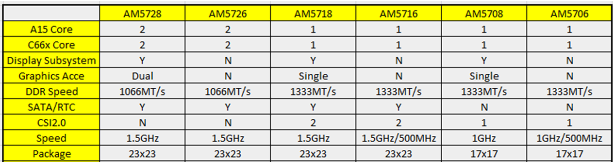
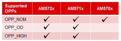
Code Composer Studio (CCS) and Emulation support
TI Supports following evaluation platform for AM57xx class of devices:
When developer selects any of the above platforms in Code composer Studio, the target configuration automatically brings in the required initialization files and GEL files to configure the clocks, slave cores, external memory.
If you are using a custom platform or AM5708 device that is not available on a TI Evaluation platform, you can follow the steps provided below to connect to the SOC by reusing the GEL files that are provided for TI evaluation platforms. For example, here we demonstrate how you can create a target configuration for AM570x and connect to the device if your board design is based of one of TI evalauation platforms listed below. The assumption here is that the custom board is based off AM571X IDK platform
Note
Support for AM5708 was added to Sitara Chip Support Package 1.3.4 in Code composer Studio. If you don`t see the device definition in CCS, then you can update the Sitara Chip Support package by going to Help->Check Updates
Step 1: Select the AM570x part number that is populated on your custom platform:
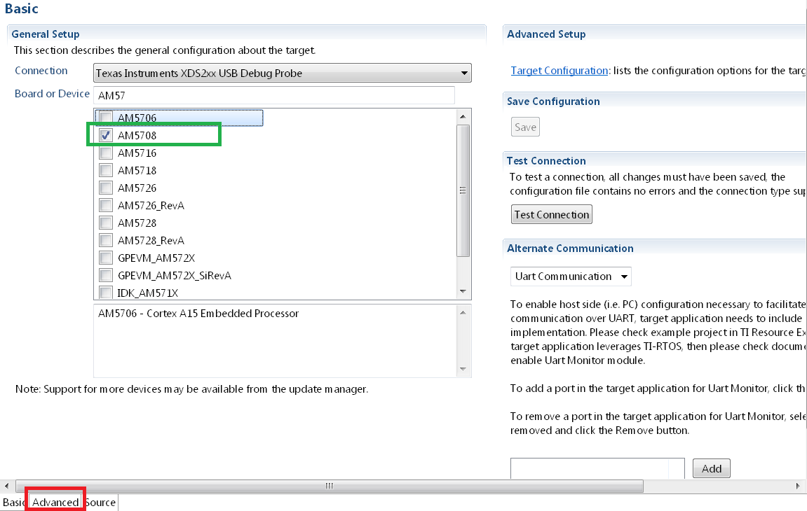
Step 2: Setup the GEL files for the SOC Go to the Advanced Tab as shown in the previous screenshot and update startup GEL file in the A15 Core as shown in the screenshot below
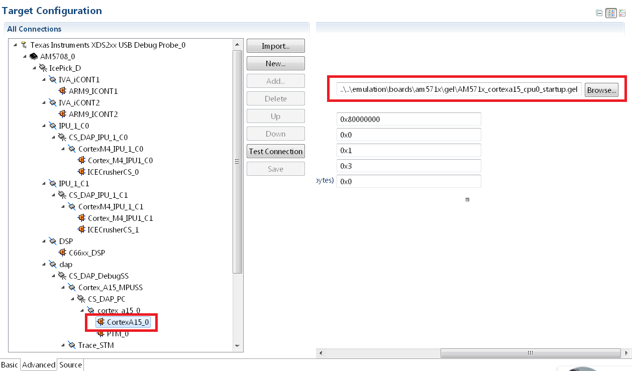
Board Library Changes to Consider for Using Processor SDK RTOS
Clock and PRCM Updates to consider
The board library provides setting for OPP_NOM, OPP_OD and OPP_HIGH in the PLL settings using 20 MHz input clock that has been used on the AM572x GP EVM as well as the AM571x IDK platform. This allows customers to setup the MPU to 1.5, 1.176 and 1GHz. For AM570x devices, we support the “J” and the “D” variant which support the following max speeds on the DPLLs:

When using the “J” speed grade, ensure that the DPLLs in the board set the DPLL to OPP_NOM and not for OPP_OD or OPP_HIGH.
To do this, you can invoke the Board_Init from your application using either
Board_initCfg boardCfg;
boardCfg = BOARD_INIT_PLL_OPP_NOM;
boardCfg |= BOARD_INIT_UNLOCK_MMR |
       BOARD_INIT_MODULE_CLOCK |
       BOARD_INIT_PINMUX_CONFIG |
       BOARD_INIT_DDR |
       BOARD_INIT_UART_STDIO |
       BOARD_INIT_WATCHDOG_DISABLE;
/* Board Library Init. */
   Board_init(boardCfg);
Note
When bootloading direct from flash media, this change may also be required in the SBL code
When using “D” rated parts that run at 500 MHz, in addition to the above configuration, you will also need to modify OPP_NOM settings in the board library by updating the DPLL setting for MPU and DSP in the file <BoardName>_pll.c as shown below:
Step1 : Update MPU, DSP, IVA and GPU DPLL setting
- MPU DPLL Changes:
/* Default to OPP_NOM */
     /* 500MHz at 20MHz sys_clk */
     mpuPllcParam.mult = 250U;
     mpuPllcParam.div = 9U;
     mpuPllcParam.dccEnable = 0U;
     mpuPllcParam.divM2 = 1U;
- DSP DPLL Changes:
/* 500MHz at 20MHz sys_clk */
dspPllcParam.mult = 130U;
dspPllcParam.div = 3U;
dspPllcParam.divM2 = 1U;
dspPllcParam.divM3 = 3U;
- Remove IVA and GPU PLL settings
Since IVA and GPU modules are not available on the device, we recommend removing the ivaPLL and gpuPLL settings in board.
              /* Default to OPP_NOM */
              /* 388.3MHz at 20MHz sys_clk */
-                ivaPllcParam.mult = 233U;
-                ivaPllcParam.div = 3U;
-                ivaPllcParam.divM2 = 3U;
             /* Default to OPP_NOM */
             /* 425MHz at 20MHz sys_clk */
-                gpuPllcParam.mult = 170U;
-                gpuPllcParam.div = 3U;
-                gpuPllcParam.divM2 = 2U;
Step 2 : Disable clocks configuration and wakeup for IVA in PRCM
- Remove IVA wakeup and Module configuration
The following updates need to be made in the file <BoardName>_clock.c to remove IVA wakeup and clock configuration
-        CSL_FINST(ivaCmReg->CM_IVA_CLKSTCTRL_REG,
-        IVA_CM_CORE_CM_IVA_CLKSTCTRL_REG_CLKTRCTRL, SW_WKUP);
   /* PRCM Specialized module mode setting functions */
-   CSL_FINST(ivaCmReg->CM_IVA_SL2_CLKCTRL_REG,
-       IVA_CM_CORE_CM_IVA_SL2_CLKCTRL_REG_MODULEMODE, AUTO);
-  while(CSL_IVA_CM_CORE_CM_IVA_SL2_CLKCTRL_REG_IDLEST_DISABLE ==
-      CSL_FEXT(ivaCmReg->CM_IVA_SL2_CLKCTRL_REG,
-       IVA_CM_CORE_CM_IVA_SL2_CLKCTRL_REG_IDLEST));
-   CSL_FINST(ivaCmReg->CM_IVA_IVA_CLKCTRL_REG,
-       IVA_CM_CORE_CM_IVA_IVA_CLKCTRL_REG_MODULEMODE, AUTO);
-   while(CSL_IVA_CM_CORE_CM_IVA_IVA_CLKCTRL_REG_IDLEST_DISABLE ==
-      CSL_FEXT(ivaCmReg->CM_IVA_IVA_CLKCTRL_REG,
-       IVA_CM_CORE_CM_IVA_IVA_CLKCTRL_REG_IDLEST));
Configure DDR Interfaces
An important one to consider is the speed of the DDR memory. The clock for the DDR is selected using the same dplls structure. Some higher speed grade parts support a 667 MHz DDR clock, but some of the lower speed grade parts only support a 533 MHz DDR3 clock. Make sure to choose the appropriate DDR clock for the device on the custom board.
Over in the board/src/<BoardName>/<BoardName_ddr>.c file, make sure that the EMIF is being configured correctly for the appropriate speed, and that the appropriate number of EMIFs is being selected to match the part being used. AM572x part has 2 DDR interfaces running at 533 MHz and the AM571x (and AM570x) only have one running at 667 MHz. This code can be kept or removed by the board port. As changes are made, the code must make sure to configure the new board correctly, with the appropriate number of DDR interfaces and speed configuration.
For AM571x and AM570x, make sure to use the code for the AM571x IDK in board/src/<BoardName>/<BoardName_ddr>.c to select 1 EMIF:
/* MA_LISA_MAP_i */
hMampuLsm->MAP_0 = 0x80600100U;
/* DMM_LISA_MAP_i */
hDmmCfg->LISA_MAP[0U] = 0x80600100U;
For AM572x, this is mapped as following
/* MA_LISA_MAP_i */
hMampuLsm->MAP_0 = 0x80740300;
hMampuLsm->MAP_1 = 0x80740300;
/* DMM_LISA_MAP_i */
hDmmCfg->LISA_MAP[0U] = 0x80740300;
hDmmCfg->LISA_MAP[1U] = 0x80740300;
Note
Processor SDK RTOS provides am570x_ddr.c file in the idkAM571x board library for reference for configuring DDR on AM570x parts
Pinmux Changes to Consider
- For part number where the Display subsystem or SATA is not available, the pins can be configured to any other pin functionality that may be required in the system. If you don`t need to use these pins, we recommend that you leave these pins in default MUXMODE and terminate the pinmux as recommended in the Schematics Checklist.
- There is no pinmux setting for CSI2 module so you can leave the MUXMODE=0 on those pins if there is no instance of the peripheral
Note
Processor SDK RTOS provides board/src/idkAM571x/include/am570x_pinmux.h file in the idkAM571x board library for reference for configuring pinmux on AM570x based hardware platform
Driver SOC Module clock changes
Some control drivers use default Module input clock frequency settings in <module>_soc.c file that gets used by the Low level drivers to configure the peripheral clocks. The default module input clock frequency is set to the OPP_NOM values that are available on the superset variant of the device so if you are using lower speed grades. Ensure you change the default to match the module clock on the 500 MHz settings or you can use the following sequence to update the settings. Code below describes how the SPI driver module input clock frequency can be modified
SPI_v1_HWAttrs spi_cfg;
/* Get the default SPI init configurations */
SPI_socGetInitCfg(TEST_SPI_PORT, &spi_cfg);
/* Modify the default SPI configurations if necessary */
spi_cfg.inputClkFreq = 24000000;
/* Set the default SPI init configurations */
SPI_socSetInitCfg(TEST_SPI_PORT, &spi_cfg);
Useful Utilities
Support
For any questions related Usage of AM572x, AM571x and AM570x devices, please post your question on TI E2E Forums
10.2.4. System Integration
10.2.4.1. Create DSP and IPU firmware using PDK drivers and IPC to load from ARM Linux on AM57xx devices
Introduction
This article is geared toward AM57xx users that are running Linux on the Cortex A15. The goal is to help users understand how to gain entitlement to the DSP (c66x) and IPU (Cortex M4) subsystems of the AM57xx.
AM572x device has two IPU subsystems (IPUSS), each of which has 2 cores. IPU2 is used as a controller in multi-media applications, so if you have Processor SDK Linux running, chances are that IPU2 already has firmware loaded. However, IPU1 is open for general purpose programming to offload the ARM tasks.
There are many facets to this task: building, loading, debugging, MMUs, memory sharing, etc. This article intends to take incremental steps toward understanding all of those pieces.
Software Dependencies to Get Started
Prerequisites
- Processor SDK Linux for AM57xx (Version 3.01 or newer needed)
- Processor SDK RTOS for AM57xx
- Code Composer Studio (choose version as specified on Proc SDK download page)
Note
Please be sure that you have the same version number for both Processor SDK RTOS and Linux.
For reference within the context of this wiki page, the Linux SDK is installed at the following location:
/mnt/data/user/ti-processor-sdk-linux-am57xx-evm-xx.xx.xx.xx
├── bin
├── board-support
├── docs
├── example-applications
├── filesystem
├── ipc-build.txt
├── linux-devkit
├── Makefile
├── Rules.make
└── setup.sh
The RTOS SDK is installed at:
/mnt/data/user/my_custom_install_sdk_rtos_am57xx_xx.xx
├── bios_6_xx_xx_xx
├── cg_xml
├── ctoolslib_x_x_x_x
├── dsplib_c66x_x_x_x_x
├── edma3_lld_2_xx_xx_xx
├── framework_components_x_xx_xx_xx
├── imglib_c66x_x_x_x_x
├── ipc_3_xx_xx_xx
├── mathlib_c66x_3_x_x_x
├── ndk_2_xx_xx_xx
├── opencl_rtos_am57xx_01_01_xx_xx
├── openmp_dsp_am57xx_2_04_xx_xx
├── pdk_am57xx_x_x_x
├── processor_sdk_rtos_am57xx_x_xx_xx_xx
├── uia_2_xx_xx_xx
├── xdais_7_xx_xx_xx
CCS is installed at:
/mnt/data/user/ti/my_custom_ccs_x.x.x_install
├── ccsvX
│   ├── ccs_base
│   ├── doc
│   ├── eclipse
│   ├── install_info
│   ├── install_logs
│   ├── install_scripts
│   ├── tools
│   ├── uninstall_ccs
│   ├── uninstall_ccs.dat
│   ├── uninstallers
│   └── utils
├── Code Composer Studio x.x.x.desktop
└── xdctools_x_xx_xx_xx_core
    ├── bin
    ├── config.jar
    ├── docs
    ├── eclipse
    ├── etc
    ├── gmake
    ├── include
    ├── package
    ├── packages
    ├── package.xdc
    ├── tconfini.tcf
    ├── xdc
    ├── xdctools_3_xx_xx_xx_manifest.html
    ├── xdctools_3_xx_xx_xx_release_notes.html
    ├── xs
    └── xs.x86U
Typical Boot Flow on AM572x for ARM Linux users
AM57xx SOC’s have multiple processor cores - Cortex A15, C66x DSP’s and ARM M4 cores. The A15 typically runs a HLOS like Linux/QNX/Android and the remotecores(DSP’s and M4’s) run a RTOS. In the normal operation, boot loader(U-Boot/SPL) boots and loads the A15 with the HLOS. The A15 boots the DSP and the M4 cores.
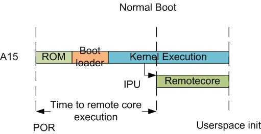
In this sequence, the interval between the Power on Reset and the remotecores (i.e. the DSP’s and the M4’s) executing is dependent on the HLOS initialization time.
Getting Started with IPC Linux Examples
The figure below illustrates how remoteproc/rpmsg driver from ARM Linux kernel communicates with IPC driver on slave processor (e.g. DSP, IPU, etc) running RTOS.
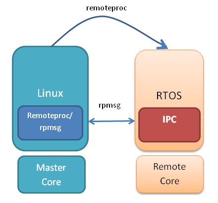
In order to setup IPC on slave cores, we provide some pre-built examples in IPC package that can be run from ARM Linux. The subsequent sections describe how to build and run this examples and use that as a starting point for this effort.
Building the Bundled IPC Examples
The instructions to build IPC examples found under ipc_3_xx_xx_xx/examples/DRA7XX_linux_elf have been provided in the `Processor_SDK IPC Quick Start Guide <https://processors.wiki.ti.com/index.php/Processor_SDK_IPC_Quick_Start_Guide#Build_IPC_Linux_examples>`__.
Let’s focus on one example in particular, ex02_messageq, which is located at <rtos-sdk-install-dir>/ipc_3_xx_xx_xx/examples/DRA7XX_linux_elf/ex02_messageq. Here are the key files that you should see after a successful build:
├── dsp1
│   └── bin
│       ├── debug
│       │   └── server_dsp1.xe66
│       └── release
│           └── server_dsp1.xe66
├── dsp2
│   └── bin
│       ├── debug
│       │   └── server_dsp2.xe66
│       └── release
│           └── server_dsp2.xe66
├── host
│       ├── debug
│       │   └── app_host
│       └── release
│           └── app_host
├── ipu1
│   └── bin
│       ├── debug
│       │   └── server_ipu1.xem4
│       └── release
│           └── server_ipu1.xem4
└── ipu2
    └── bin
        ├── debug
        │   └── server_ipu2.xem4
        └── release
            └── server_ipu2.xem4
Running the Bundled IPC Examples
On the target, let’s create a directory called ipc-starter:
root@am57xx-evm:~# mkdir -p /home/root/ipc-starter
root@am57xx-evm:~# cd /home/root/ipc-starter/
You will need to copy the ex02_messageq directory of your host PC to that directory on the target (through SD card, NFS export, SCP, etc.). You can copy the entire directory, though we’re primarily interested in these files:
- dsp1/bin/debug/server_dsp1.xe66
- dsp2/bin/debug/server_dsp2.xe66
- host/bin/debug/app_host
- ipu1/bin/debug/server_ipu1.xem4
- ipu2/bin/debug/server_ipu2.xem4
The remoteproc driver is hard-coded to look for specific files when loading the DSP/M4. Here are the files it looks for:
- /lib/firmware/dra7-dsp1-fw.xe66
- /lib/firmware/dra7-dsp2-fw.xe66
- /lib/firmware/dra7-ipu1-fw.xem4
- /lib/firmware/dra7-ipu2-fw.xem4
These are generally a soft link to the intended executable. So for example, let’s update the DSP1 executable on the target:
root@am57xx-evm:~# cd /lib/firmware/
root@am57xx-evm:/lib/firmware# rm dra7-dsp1-fw.xe66
root@am57xx-evm:/lib/firmware# ln -s /home/root/ipc-starter/ex02_messageq/dsp1/bin/debug/server_dsp1.xe66 dra7-dsp1-fw.xe66
To reload DSP1 with this new executable, we perform the following steps:
root@am57xx-evm:/lib/firmware# cd /sys/bus/platform/drivers/omap-rproc/
root@am57xx-evm:/sys/bus/platform/drivers/omap-rproc# echo 40800000.dsp > unbind
[27639.985631] omap_hwmod: mmu0_dsp1: _wait_target_disable failed
[27639.991534] omap-iommu 40d01000.mmu: 40d01000.mmu: version 3.0
[27639.997610] omap-iommu 40d02000.mmu: 40d02000.mmu: version 3.0
[27640.017557] omap_hwmod: mmu1_dsp1: _wait_target_disable failed
[27640.030571] omap_hwmod: mmu0_dsp1: _wait_target_disable failed
[27640.036605]  remoteproc2: stopped remote processor 40800000.dsp
[27640.042805]  remoteproc2: releasing 40800000.dsp
root@am57xx-evm:/sys/bus/platform/drivers/omap-rproc# echo 40800000.dsp > bind
[27645.958613] omap-rproc 40800000.dsp: assigned reserved memory node dsp1_cma@99000000
[27645.966452]  remoteproc2: 40800000.dsp is available
[27645.971410]  remoteproc2: Note: remoteproc is still under development and considered experimental.
[27645.980536]  remoteproc2: THE BINARY FORMAT IS NOT YET FINALIZED, and backward compatibility isn't yet guaranteed.
root@am57xx-evm:/sys/bus/platform/drivers/omap-rproc# [27646.008171]  remoteproc2: powering up 40800000.dsp
[27646.013038]  remoteproc2: Booting fw image dra7-dsp1-fw.xe66, size 4706800
[27646.028920] omap_hwmod: mmu0_dsp1: _wait_target_disable failed
[27646.034819] omap-iommu 40d01000.mmu: 40d01000.mmu: version 3.0
[27646.040772] omap-iommu 40d02000.mmu: 40d02000.mmu: version 3.0
[27646.058323]  remoteproc2: remote processor 40800000.dsp is now up
[27646.064772] virtio_rpmsg_bus virtio2: rpmsg host is online
[27646.072271]  remoteproc2: registered virtio2 (type 7)
[27646.078026] virtio_rpmsg_bus virtio2: creating channel rpmsg-proto addr 0x3d
More info related to loading firmware to the various cores can be found here.
Finally, we can run the example on DSP1:
root@am57xx-evm:/sys/bus/platform/drivers/omap-rproc# cd /home/root/ipc-starter/ex02_messageq/host/bin/debug
root@am57xx-evm:~/ipc-starter/ex02_messageq/host/bin/debug# ./app_host DSP1
--> main:
[33590.700700] omap_hwmod: mmu0_dsp2: _wait_target_disable failed
[33590.706609] omap-iommu 41501000.mmu: 41501000.mmu: version 3.0
[33590.718798] omap-iommu 41502000.mmu: 41502000.mmu: version 3.0
--> Main_main:
--> App_create:
App_create: Host is ready
<-- App_create:
--> App_exec:
App_exec: sending message 1
App_exec: sending message 2
App_exec: sending message 3
App_exec: message received, sending message 4
App_exec: message received, sending message 5
App_exec: message received, sending message 6
App_exec: message received, sending message 7
App_exec: message received, sending message 8
App_exec: message received, sending message 9
App_exec: message received, sending message 10
App_exec: message received, sending message 11
App_exec: message received, sending message 12
App_exec: message received, sending message 13
App_exec: message received, sending message 14
App_exec: message received, sending message 15
App_exec: message received
App_exec: message received
App_exec: message received
<-- App_exec: 0
--> App_delete:
<-- App_delete:
<-- Main_main:
<-- main:
The similar procedure can be used for DSP2/IPU1/IPU2 also to update the soft link of the firmware, reload the firmware at run-time, and run the host binary from A15.
Understanding the Memory Map
Overall Linux Memory Map
root@am57xx-evm:~# cat /proc/iomem
[snip...]
58060000-58078fff : core
58820000-5882ffff : l2ram
58882000-588820ff : /ocp/mmu@58882000
80000000-9fffffff : System RAM
80008000-808d204b : Kernel code
80926000-809c96bf : Kernel data
a0000000-abffffff : CMEM
ac000000-ffcfffff : System RAM
CMA Carveouts
root@am57xx-evm:~# dmesg | grep -i cma
[    0.000000] Reserved memory: created CMA memory pool at 0x0000000095800000, size 56 MiB
[    0.000000] Reserved memory: initialized node ipu2_cma@95800000, compatible id shared-dma-pool
[    0.000000] Reserved memory: created CMA memory pool at 0x0000000099000000, size 64 MiB
[    0.000000] Reserved memory: initialized node dsp1_cma@99000000, compatible id shared-dma-pool
[    0.000000] Reserved memory: created CMA memory pool at 0x000000009d000000, size 32 MiB
[    0.000000] Reserved memory: initialized node ipu1_cma@9d000000, compatible id shared-dma-pool
[    0.000000] Reserved memory: created CMA memory pool at 0x000000009f000000, size 8 MiB
[    0.000000] Reserved memory: initialized node dsp2_cma@9f000000, compatible id shared-dma-pool
[    0.000000] cma: Reserved 24 MiB at 0x00000000fe400000
[    0.000000] Memory: 1713468K/1897472K available (6535K kernel code, 358K rwdata, 2464K rodata, 332K init, 289K bss, 28356K reserved, 155648K  cma-reserved, 1283072K highmem)
[    5.492945] omap-rproc 58820000.ipu: assigned reserved memory node ipu1_cma@9d000000
[    5.603289] omap-rproc 55020000.ipu: assigned reserved memory node ipu2_cma@95800000
[    5.713411] omap-rproc 40800000.dsp: assigned reserved memory node dsp1_cma@9b000000
[    5.771990] omap-rproc 41000000.dsp: assigned reserved memory node dsp2_cma@9f000000
From the output above, we can derive the location and size of each CMA carveout:
| Memory Section | Physical Address | Size |
|---|---|---|
| IPU2 CMA | 0x95800000 | 56 MB |
| DSP1 CMA | 0x99000000 | 64 MB |
| IPU1 CMA | 0x9d000000 | 32 MB |
| DSP2 CMA | 0x9f000000 | 8 MB |
| Default CMA | 0xfe400000 | 24 MB |
For details on how to adjust the sizes and locations of the DSP/IPU CMA carveouts, please see the corresponding section for changing the DSP or IPU memory map.
To adjust the size of the “Default CMA” section, this is done as part of the Linux config:
linux/arch/arm/configs/tisdk_am57xx-evm_defconfig
#
# Default contiguous memory area size:
#
CONFIG_CMA_SIZE_MBYTES=24
CONFIG_CMA_SIZE_SEL_MBYTES=y
CMEM
To view the allocation at run-time:
root@am57xx-evm:~# cat /proc/cmem

Block 0: Pool 0: 1 bufs size 0xc000000 (0xc000000 requested)

Pool 0 busy bufs:

Pool 0 free bufs:
id 0: phys addr 0xa0000000
This shows that we have defined a CMEM block at physical base address of 0xA0000000 with total size 0xc000000 (192 MB). This block contains a buffer pool consisting of 1 buffer. Each buffer in the pool (only one in this case) is defined to have a size of 0xc000000 (192 MB).
Here is where those sizes/addresses were defined for the AM57xx EVM:
linux/arch/arm/boot/dts/am57xx-evm-cmem.dtsi
{
       reserved-memory {
               #address-cells = <2>;
               #size-cells = <2>;
               ranges;

               cmem_block_mem_0: cmem_block_mem@a0000000 {
                       reg = <0x0 0xa0000000 0x0 0x0c000000>;
                       no-map;
                       status = "okay";
               };

               cmem_block_mem_1_ocmc3: cmem_block_mem@40500000 {
                       reg = <0x0 0x40500000 0x0 0x100000>;
                       no-map;
                       status = "okay";
               };
       };

       cmem {
               compatible = "ti,cmem";
               #address-cells = <1>;
               #size-cells = <0>;

               #pool-size-cells = <2>;

               status = "okay";

               cmem_block_0: cmem_block@0 {
                       reg = <0>;
                       memory-region = <&cmem_block_mem_0>;
                       cmem-buf-pools = <1 0x0 0x0c000000>;
               };

               cmem_block_1: cmem_block@1 {
                       reg = <1>;
                       memory-region = <&cmem_block_mem_1_ocmc3>;
               };
       };
};
Changing the DSP Memory Map
First, it is important to understand that there are a pair of Memory Management Units (MMUs) that sit between the DSP subsystems and the L3 interconnect. One of these MMUs is for the DSP core and the other is for its local EDMA. They both serve the same purpose of translating virtual addresses (i.e. the addresses as viewed by the DSP subsystem) into physical addresses (i.e. addresses as viewed from the L3 interconnect).
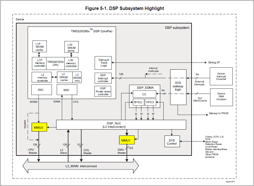
DSP Physical Addresses
The physical location where the DSP code/data will actually reside is defined by the CMA carveout. To change this location, you must change the definition of the carveout. The DSP carveouts are defined in the Linux dts file. For example for the AM57xx EVM:
linux/arch/arm/boot/dts/am57xx-beagle-x15-common.dtsi
{
        dsp1_cma_pool: dsp1_cma@99000000 {
                compatible = "shared-dma-pool";
                reg = <0x0 0x99000000 0x0 0x4000000>;
                reusable;
                status = "okay";
        };

        dsp2_cma_pool: dsp2_cma@9f000000 {
                compatible = "shared-dma-pool";
                reg = <0x0 0x9f000000 0x0 0x800000>;
                reusable;
                status = "okay";
        };
};
You are able to change both the size and location. Be careful not to overlap any other carveouts!
Note
The two location entries for a given DSP must be identical!
Additionally, when you change the carveout location, there is a corresponding change that must be made to the resource table. For starters, if you’re making a memory change you will need a custom resource table. The resource table is a large structure that is the “bridge” between physical memory and virtual memory. This structure is utilized for configuring the MMUs that sit in front of the DSP subsystem. There is detailed information available in the article IPC Resource customTable.
Once you’ve created your custom resource table, you must update the address of PHYS_MEM_IPC_VRING to be the same base address as your corresponding CMA.
#if defined (VAYU_DSP_1)
#define PHYS_MEM_IPC_VRING      0x99000000
#elif defined (VAYU_DSP_2)
#define PHYS_MEM_IPC_VRING      0x9F000000
#endif
Note
The PHYS_MEM_IPC_VRING definition from the resource table must match the address of the associated CMA carveout!
DSP Virtual Addresses
These addresses are the ones seen by the DSP subsystem, i.e. these will be the addresses in your linker command files, etc.
You must ensure that the sizes of your sections are consistent with the corresponding definitions in the resource table. You should create your own resource table in order to modify the memory map. This is describe in the wiki page IPC Resource customTable. You can look at an existing resource table inside IPC:
ipc/packages/ti/ipc/remoteproc/rsc_table_vayu_dsp.h
{
    TYPE_CARVEOUT,
    DSP_MEM_TEXT, 0,
    DSP_MEM_TEXT_SIZE, 0, 0, "DSP_MEM_TEXT",
},

{
    TYPE_CARVEOUT,
    DSP_MEM_DATA, 0,
    DSP_MEM_DATA_SIZE, 0, 0, "DSP_MEM_DATA",
},

{
    TYPE_CARVEOUT,
    DSP_MEM_HEAP, 0,
    DSP_MEM_HEAP_SIZE, 0, 0, "DSP_MEM_HEAP",
},

{
    TYPE_CARVEOUT,
    DSP_MEM_IPC_DATA, 0,
    DSP_MEM_IPC_DATA_SIZE, 0, 0, "DSP_MEM_IPC_DATA",
},

{
    TYPE_TRACE, TRACEBUFADDR, 0x8000, 0, "trace:dsp",
},


{
    TYPE_DEVMEM,
    DSP_MEM_IPC_VRING, PHYS_MEM_IPC_VRING,
    DSP_MEM_IPC_VRING_SIZE, 0, 0, "DSP_MEM_IPC_VRING",
},
Let’s have a look at some of these to understand them better. For example:
{
    TYPE_CARVEOUT,
    DSP_MEM_TEXT, 0,
    DSP_MEM_TEXT_SIZE, 0, 0, "DSP_MEM_TEXT",
},
Key points to note are:
- The “TYPE_CARVEOUT” indicates that the physical memory backing this entry will come from the associated CMA pool.
- DSP_MEM_TEXT is a #define earlier in the code providing the address for the code section. It is 0x95000000 by default. This must correspond to a section from your DSP linker command file, i.e. EXT_CODE (or whatever name you choose to give it) must be linked to the same address.
- DSP_MEM_TEXT_SIZE is the size of the MMU pagetable entry being created (1MB in this particular instance). The actual amount of linked code in the corresponding section of your executable must be less than or equal to this size.
Let’s take another:
{
    TYPE_TRACE, TRACEBUFADDR, 0x8000, 0, "trace:dsp",
},
Key points are:
- The “TYPE_TRACE” indicates this is for trace info.
- The TRACEBUFADDR is defined earlier in the file as &ti_trace_SysMin_Module_State_0_outbuf__A. That corresponds to the symbol used in TI-RTOS for the trace buffer.
- The “0x8000” is the size of the MMU mapping. The corresponding size in the cfg file should be the same (or less). It looks like this: SysMin.bufSize = 0x8000;
Finally, let’s look at a TYPE_DEVMEM example:
{
    TYPE_DEVMEM,
    DSP_PERIPHERAL_L4CFG, L4_PERIPHERAL_L4CFG,
    SZ_16M, 0, 0, "DSP_PERIPHERAL_L4CFG",
},
Key points:
- The “TYPE_DEVMEM” indicates that we are making an MMU mapping, but this does not come from the CMA pool. This is intended for mapping peripherals, etc. that already exist in the device memory map.
- DSP_PERIPHERAL_L4CFG (0x4A000000) is the virtual address while L4_PERIPHERAL_L4CFG (0x4A000000) is the physical address. This is an identity mapping, meaning that peripherals can be referenced by the DSP using their physical address.
DSP Access to Peripherals
The default resource table creates the following mappings:
| Virtual Address | Physical Address | Size | Comment |
|---|---|---|---|
| 0x4A000000 | 0x4A000000 | 16 MB | L4CFG + L4WKUP |
| 0x48000000 | 0x48000000 | 2 MB | L4PER1 |
| 0x48400000 | 0x48400000 | 4 MB | L4PER2 |
| 0x48800000 | 0x48800000 | 8 MB | L4PER3 |
| 0x54000000 | 0x54000000 | 16 MB | L3_INSTR + CT_TBR |
| 0x4E000000 | 0x4E000000 | 1 MB | DMM config |
In other words, the peripherals can be accessed at their physical addresses since we use an identity mapping.
Inspecting the DSP IOMMU Page Tables at Run-Time
You can dump the DSP IOMMU page tables with the following commands:
| DSP | MMU | Command |
|---|---|---|
| DSP1 | MMU0 | cat /sys/kernel/debug/omap_iommu/40d01000.mmu/pagetable |
| DSP1 | MMU1 | cat /sys/kernel/debug/omap_iommu/40d02000.mmu/pagetable |
| DSP2 | MMU0 | cat /sys/kernel/debug/omap_iommu/41501000.mmu/pagetable |
| DSP2 | MMU1 | cat /sys/kernel/debug/omap_iommu/41502000.mmu/pagetable |
In general, MMU0 and MMU1 are being programmed identically so you really only need to take a look at one or the other to understand the mapping for a given DSP.
For example:
root@am57xx-evm:~# cat /sys/kernel/debug/omap_iommu/40d01000.mmu/pagetable
L:      da:     pte:
--------------------------
1: 0x48000000 0x48000002
1: 0x48100000 0x48100002
1: 0x48400000 0x48400002
1: 0x48500000 0x48500002
1: 0x48600000 0x48600002
1: 0x48700000 0x48700002
1: 0x48800000 0x48800002
1: 0x48900000 0x48900002
1: 0x48a00000 0x48a00002
1: 0x48b00000 0x48b00002
1: 0x48c00000 0x48c00002
1: 0x48d00000 0x48d00002
1: 0x48e00000 0x48e00002
1: 0x48f00000 0x48f00002
1: 0x4a000000 0x4a040002
1: 0x4a100000 0x4a040002
1: 0x4a200000 0x4a040002
1: 0x4a300000 0x4a040002
1: 0x4a400000 0x4a040002
1: 0x4a500000 0x4a040002
1: 0x4a600000 0x4a040002
1: 0x4a700000 0x4a040002
1: 0x4a800000 0x4a040002
1: 0x4a900000 0x4a040002
1: 0x4aa00000 0x4a040002
1: 0x4ab00000 0x4a040002
1: 0x4ac00000 0x4a040002
1: 0x4ad00000 0x4a040002
1: 0x4ae00000 0x4a040002
1: 0x4af00000 0x4a040002
The first column tells us whether the mapping is a Level 1 or Level 2 descriptor. All the lines above are a first level descriptor, so we look at the associated format from the TRM:
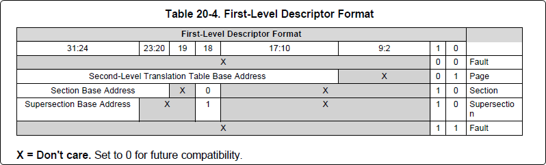
The “da” (“device address”) column reflects the virtual address. It is derived from the index into the table, i.e. there does not exist a “da” register or field in the page table. Each MB of the address space maps to an entry in the table. The “da” column is displayed to make it easy to find the virtual address of interest.
The “pte” (“page table entry”) column can be decoded according to Table 20-4 shown above. For example:
1: 0x4a000000 0x4a040002
The 0x4a040002 shows us that it is a Supersection with base address 0x4A000000. This gives us a 16 MB memory page. Note the repeated entries afterward. That’s a requirement of the MMU. Here’s an excerpt from the TRM:
Note
Supersection descriptors must be repeated 16 times, because each descriptor in the first level translation table describes 1 MiB of memory. If an access points to a descriptor that is not initialized, the MMU will behave in an unpredictable way.
Changing Cortex M4 IPU Memory Map
In order to fully understand the memory mapping of the Cortex M4 IPU Subsystems, it’s helpful to recognize that there are two distinct/independent levels of memory translation. Here’s a snippet from the TRM to illustrate:
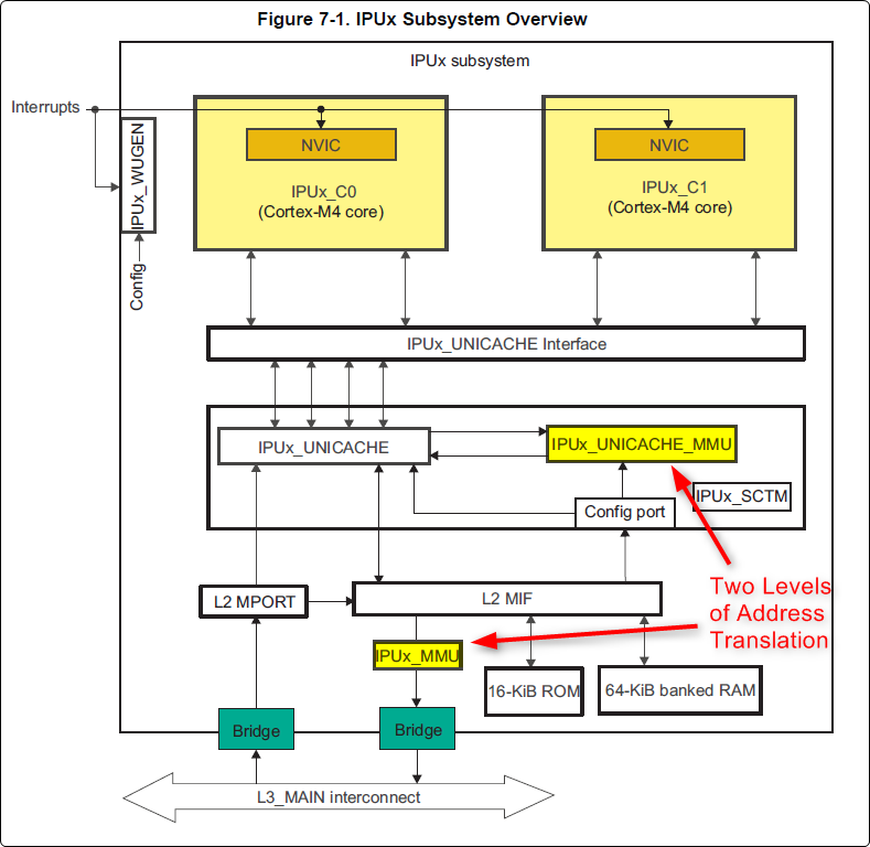
Cortex M4 IPU Physical Addresses
The physical location where the M4 code/data will actually reside is defined by the CMA carveout. To change this location, you must change the definition of the carveout. The M4 carveouts are defined in the Linux dts file. For example for the AM57xx EVM:
linux/arch/arm/boot/dts/am57xx-beagle-x15-common.dtsi
{
        ipu2_cma_pool: ipu2_cma@95800000 {
                compatible = "shared-dma-pool";
                reg = <0x0 95800000 0x0 0x3800000>;
                reusable;
                status = "okay";
        };

        ipu1_cma_pool: ipu1_cma@9d000000 {
                compatible = "shared-dma-pool";
                reg = <0x0 9d000000 0x0 0x2000000>;
                reusable;
                status = "okay";
        };
};
You are able to change both the size and location. Be careful not to overlap any other carveouts!
Note
The two location entries for a given carveout must be identical!
Additionally, when you change the carveout location, there is a corresponding change that must be made to the resource table. For starters, if you’re making a memory change you will need a custom resource table. The resource table is a large structure that is the “bridge” between physical memory and virtual memory. This structure is utilized for configuring the IPUx_MMU (not the Unicache MMU). There is detailed information available in the article IPC Resource customTable.
Once you’ve created your custom resource table, you must update the address of PHYS_MEM_IPC_VRING to be the same base address as your corresponding CMA.
#if defined(VAYU_IPU_1)
#define PHYS_MEM_IPC_VRING      0x9D000000
#elif defined (VAYU_IPU_2)
#define PHYS_MEM_IPC_VRING      0x95800000
#endif
Note
The PHYS_MEM_IPC_VRING definition from the resource table must match the address of the associated CMA carveout!
Cortex M4 IPU Virtual Addresses
Unicache MMU
The Unicache MMU sits closest to the Cortex M4. It provides the first level of address translation. The Unicache MMU is actually “self programmed” by the Cortex M4. The Unicache MMU is also referred to as the Attribute MMU (AMMU). There are a fixed number of small, medium and large pages. Here’s a snippet showing some of the key mappings:
ipc_3_43_02_04/examples/DRA7XX_linux_elf/ex02_messageq/ipu1/IpuAmmu.cfg
/*********************** Large Pages *************************/
/* Instruction Code: Large page  (512M); cacheable */
/* config large page[0] to map 512MB VA 0x0 to L3 0x0 */
AMMU.largePages[0].pageEnabled = AMMU.Enable_YES;
AMMU.largePages[0].logicalAddress = 0x0;
AMMU.largePages[0].translationEnabled = AMMU.Enable_NO;
AMMU.largePages[0].size = AMMU.Large_512M;
AMMU.largePages[0].L1_cacheable = AMMU.CachePolicy_CACHEABLE;
AMMU.largePages[0].L1_posted = AMMU.PostedPolicy_POSTED;

/* Peripheral regions: Large Page (512M); non-cacheable */
/* config large page[1] to map 512MB VA 0x60000000 to L3 0x60000000 */
AMMU.largePages[1].pageEnabled = AMMU.Enable_YES;
AMMU.largePages[1].logicalAddress = 0x60000000;
AMMU.largePages[1].translationEnabled = AMMU.Enable_NO;
AMMU.largePages[1].size = AMMU.Large_512M;
AMMU.largePages[1].L1_cacheable = AMMU.CachePolicy_NON_CACHEABLE;
AMMU.largePages[1].L1_posted = AMMU.PostedPolicy_POSTED;

/* Private, Shared and IPC Data regions: Large page (512M); cacheable */
/* config large page[2] to map 512MB VA 0x80000000 to L3 0x80000000 */
AMMU.largePages[2].pageEnabled = AMMU.Enable_YES;
AMMU.largePages[2].logicalAddress = 0x80000000;
AMMU.largePages[2].translationEnabled = AMMU.Enable_NO;
AMMU.largePages[2].size = AMMU.Large_512M;
AMMU.largePages[2].L1_cacheable = AMMU.CachePolicy_CACHEABLE;
AMMU.largePages[2].L1_posted = AMMU.PostedPolicy_POSTED;
| Page | Cortex M4 Address | Intermediate Address | Size | Comment |
|---|---|---|---|---|
| Large Page 0 | 0x00000000-0x1fffffff | 0x00000000-0x1fffffff | 512 MB | Code |
| Large Page 1 | 0x60000000-0x7fffffff | 0x60000000-0x7fffffff | 512 MB | Peripherals |
| Large Page 2 | 0x80000000-0x9fffffff | 0x80000000-0x9fffffff | 512 MB | Data |
These 3 pages are “identity” mappings, performing a passthrough of requests to the associated address ranges. These intermediate addresses get mapped to their physical addresses in the next level of translation (IOMMU).
The AMMU ranges for code and data need to be identity mappings because otherwise the remoteproc loader wouldn’t be able to match up the sections from the ELF file with the associated IOMMU mapping. These mappings should suffice for any application, i.e. no need to adjust these. The more likely area for modification is the resource table in the next section. The AMMU mappings are needed mainly to understand the full picture with respect to the Cortex M4 memory map.
IOMMU
The IOMMU sits closest to the L3 interconnect. It takes the intermediate address output from the AMMU and translates it to the physical address used by the L3 interconnect. The IOMMU is programmed by the ARM based on the associated resource table. If you’re planning any memory changes then you’ll want to make a custom resource table as described in the wiki page IPC Resource customTable.
The default resource table (which can be adapted to make a custom table) can be found at this location:
ipc/packages/ti/ipc/remoteproc/rsc_table_vayu_ipu.h
#define IPU_MEM_TEXT            0x0
#define IPU_MEM_DATA            0x80000000

#define IPU_MEM_IOBUFS          0x90000000

#define IPU_MEM_IPC_DATA        0x9F000000
#define IPU_MEM_IPC_VRING       0x60000000
#define IPU_MEM_RPMSG_VRING0    0x60000000
#define IPU_MEM_RPMSG_VRING1    0x60004000
#define IPU_MEM_VRING_BUFS0     0x60040000
#define IPU_MEM_VRING_BUFS1     0x60080000

#define IPU_MEM_IPC_VRING_SIZE  SZ_1M
#define IPU_MEM_IPC_DATA_SIZE   SZ_1M

#if defined(VAYU_IPU_1)
#define IPU_MEM_TEXT_SIZE       (SZ_1M)
#elif defined(VAYU_IPU_2)
#define IPU_MEM_TEXT_SIZE       (SZ_1M * 6)
#endif

#if defined(VAYU_IPU_1)
#define IPU_MEM_DATA_SIZE       (SZ_1M * 5)
#elif defined(VAYU_IPU_2)
#define IPU_MEM_DATA_SIZE       (SZ_1M * 48)
#endif
<snip...>
{
    TYPE_CARVEOUT,
    IPU_MEM_TEXT, 0,
    IPU_MEM_TEXT_SIZE, 0, 0, "IPU_MEM_TEXT",
},

{
    TYPE_CARVEOUT,
    IPU_MEM_DATA, 0,
    IPU_MEM_DATA_SIZE, 0, 0, "IPU_MEM_DATA",
},

{
    TYPE_CARVEOUT,
    IPU_MEM_IPC_DATA, 0,
    IPU_MEM_IPC_DATA_SIZE, 0, 0, "IPU_MEM_IPC_DATA",
},
The 3 entries above from the resource table all come from the associated IPU CMA pool (i.e. as dictated by the TYPE_CARVEOUT). The second parameter represents the virtual address (i.e. input address to the IOMMU). These addresses must be consistent with both the AMMU mapping as well as the linker command file. The ex02_messageq example from ipc defines these memory sections in the file examples/DRA7XX_linux_elf/ex02_messageq/shared/config.bld.
You can dump the IPU IOMMU page tables with the following commands:
| IPU | Command |
|---|---|
| IPU1 | cat /sys/kernel/debug/omap_iommu/58882000.mmu/pagetable |
| IPU2 | cat /sys/kernel/debug/omap_iommu/55082000.mmu/pagetable |
Please see the corresponding DSP documentation for more details on interpreting the output.
Cortex M4 IPU Access to Peripherals
The default resource table creates the following mappings:
| Virtual Address used by Cortex M4 | Address at output of Unicache MMU | Address at output of IOMMU | Size | Comment |
|---|---|---|---|---|
| 0x6A000000 | 0x6A000000 | 0x4A000000 | 16 MB | L4CFG + L4WKUP |
| 0x68000000 | 0x68000000 | 0x48000000 | 2 MB | L4PER1 |
| 0x68400000 | 0x68400000 | 0x48400000 | 4 MB | L4PER2 |
| 0x68800000 | 0x68800000 | 0x48800000 | 8 MB | L4PER3 |
| 0x74000000 | 0x74000000 | 0x54000000 | 16 MB | L3_INSTR + CT_TBR |
Example: Accessing UART5 from IPU
- For this example, it’s assumed the pin-muxing was already setup in the bootloader. If that’s not the case, you would need to do that here.
- The UART5 module needs to be enabled via the CM_L4PER_UART5_CLKCTRL register. This is located at physical address 0x4A009870. So from the M4 we would program this register at virtual address 0x6A009870. Writing a value of 2 to this register will enable the peripheral.
- After completing the previous step, the UART5 registers will become accessible. Normally UART5 is accessible at physical base address 0x48066000. This would correspondingly be accessed from the IPU at 0x68066000.
Power Management
The IPUs and DSPs auto-idle by default. This can prevent you from being able to connect to the device using JTAG or from accessing local memory via devmem2. There are some options sprinkled throughout sysfs that are needed in order to force these subsystems on, as is sometimes needed for development and debug purposes.
There are some hard-coded device names that originate in the device tree (dra7.dtsi) that are needed for these operations:
| Remote Core | Definition in dra7.dtsi | System FS Name |
|---|---|---|
| IPU1 | ipu@58820000 | 58820000.ipu |
| IPU2 | ipu@55020000 | 55020000.ipu |
| DSP1 | dsp@40800000 | 40800000.dsp |
| DSP2 | dsp@41000000 | 41000000.dsp |
| ICSS1-PRU0 | pru@4b234000 | 4b234000.pru0 |
| ICSS1-PRU1 | pru@4b238000 | 4b238000.pru1 |
| ICSS2-PRU0 | pru@4b2b4000 | 4b2b4000.pru0 |
| ICSS2-PRU1 | pru@4b2b8000 | 4b2b8000.pru1 |
To map these System FS names to the associated remoteproc entry, you can run the following commands:
root@am57xx-evm:~# ls -l /sys/kernel/debug/remoteproc/
root@am57xx-evm:~# cat /sys/kernel/debug/remoteproc/remoteproc*/name
The results of the commands will be a one-to-one mapping. For example, 58820000.ipu corresponds with remoteproc0.
Similarly, to see the power state of each of the cores:
root@am57xx-evm:~# cat /sys/class/remoteproc/remoteproc*/state
The state can be suspended, running, offline, etc. You can only attach JTAG if the state is “running”. If it shows as “suspended” then you must force it to run. For example, let’s say DSP0 is “suspended”. You can run the following command to force it on:
root@am57xx-evm:~# echo on > /sys/bus/platform/devices/40800000.dsp/power/control
The same is true for any of the cores, but replace 40800000.dsp with the associated System FS name from the chart above.
Adding IPC to an Existing TI-RTOS Application on slave cores
Adding IPC to an existing TI RTOS application on the DSP
A common thing people want to do is take an existing DSP application and add IPC to it. This is common when migrating from a DSP only solution to a heterogeneous SoC with an Arm plus a DSP. This is the focus of this section.
In order to describe this process, we need an example test case to work with. For this purpose, we’ll be using the GPIO_LedBlink_evmAM572x_c66xExampleProject example that’s part of the PDK (installed as part of the Processor SDK RTOS). You can find it at c:/ti/pdk_am57xx_1_0_4/packages/MyExampleProjects/GPIO_LedBlink_evmAM572x_c66xExampleProject. This example uses SYS/BIOS and blinks the USER0 LED on the AM572x GP EVM, it’s labeled D4 on the EVM silkscreen just to the right of the blue reset button.
There were several steps taken to make this whole process work, each of which will be described in following sections
- Build and run the out-of-box LED blink example on the EVM using Code Composer Studio (CCS)
- Take the ex02_message example from the IPC software bundle and turn it into a CCS project. Build it and modify the Linux startup code to use this new image. This is just a sanity check step to make sure we can build the IPC examples in CCS and have them run at boot up on the EVM.
- In CCS, make a clone of the out-of-box LED example and rename it to denote it’s the IPC version of the example. Then using the ex02_messageq example as a reference, add in the IPC pieces to the LED example. Build from CCS then add it to the Linux firmware folder.
Running LED Blink PDK Example from CCS
TODO - Fill this section in with instructions on how to run the LED blink example using JTAG and CCS after the board has booted Linux.
Note
Some edits were made to the LED blink example to allow it to run
in a Linux environment, specifically, removed the GPIO interrupts and then added a Clock object to call the LED GPIO toggle function on a periodic bases.
Make CCS project out of ex02_messageq IPC example
TODO - fill this section in with instructions on how to make a CCS project out of the IPC example source files.
Add IPC to the LED Blink Example
The first step is to clone our out-of-box LED blink CCS project and rename it to denote it’s using IPC. The easiest way to do this is using CCS. Here are the steps...
- In the Edit perspective, go into your Project Explorer window and right click on your GPIO_LedBlink_evmAM572x+c66xExampleProject project and select copy from the pop-up menu. Maske sure the project is not is a closed state.
- Rick click in and empty area of the project explorer window and select past.
- A dialog box pops up, modify the name to denote it’s using IPC. A good name is GPIO_LedBlink_evmAM572x+c66xExampleProjec_with_ipc.
This is the project we’ll be working with from here on. The next thing we want to do is select the proper RTSC platform and other components. To do this, follow these steps.
- Right click on the GPIO_LedBlink_evmAM572x+c66xExampleProjec_with_ipc project and select Properties
- In the left hand pane, click on CCS General.
- On the right hand side, click on the RTSC tab
- For XDCtools version: select 3.32.0.06_core
- In the list of Products and Repositories, check the following...
- IPC 3.43.2.04
- SYS/BIOS 6.45.1.29
- am57xx PDK 1.0.4
- For Target, select ti.targets.elf.C66
- For Platform, select ti.platforms.evmDRA7XX
- Once the platform is selected, edit its name buy hand and append :dsp1 to the end. After this it should be ti.platforms.evmDRA7XX:dsp1
- Go ahead and leave the Build-profile set to debug.
- Hit the OK button.
Now we want to copy configuration and source files from the ex02_messageq IPC example into our project. The IPC example is located at C:/ti/ipc_3_43_02_04/examples/DRA7XX_linux_elf/ex02_messageq. To copy files into your CCS project, you can simply select the files you want in Windows explorer then drag and drop them into your project in CCS.
Copy these files into your CCS project...
- C:/ti/ipc_3_43_02_04/examples/DRA7XX_linux_elf/ex02_messageq/shared/AppCommon.h
- C:/ti/ipc_3_43_02_04/examples/DRA7XX_linux_elf/ex02_messageq/shared/config.bld
- C:/ti/ipc_3_43_02_04/examples/DRA7XX_linux_elf/ex02_messageq/shared/ipc.cfg.xs
Now copy these files into your CCS project...
- C:/ti/ipc_3_43_02_04/examples/DRA7XX_linux_elf/ex02_messageq/dsp1/Dsp1.cfg
- C:/ti/ipc_3_43_02_04/examples/DRA7XX_linux_elf/ex02_messageq/dsp1/MainDsp1.c
- C:/ti/ipc_3_43_02_04/examples/DRA7XX_linux_elf/ex02_messageq/dsp1/Server.c
- C:/ti/ipc_3_43_02_04/examples/DRA7XX_linux_elf/ex02_messageq/dsp1/Server.h
Note
When you copy Dsp1.cfg into your CCS project, it should show up greyed out. This is because the LED blink example already has a cfg file (gpio_test_evmAM572x.cfg). The Dsp1.cfg will be used for copying and pasting. When it’s all done, you can delete it from your project.
Finally, you will likely want to use a custom resource table so copy these files into your CCS project...
- C:/ti/ipc_3_43_02_04/packages/ti/ipc/remoteproc/rsc_table_vayu_dsp.h
- C:/ti/ipc_3_43_02_04/packages/ti/ipc/remoteproc/rsc_types.h
The rsc_table_vayu_dsp.h file defines an initialized structure so let’s make a .c source file.
- In your CCS project, rename rsc_table_vayu_dsp.h to rsc_table_vayu_dsp.c
- Open up Dsp1.cfg using a text editor (don’t open it using the GUI). Right click on it and select Open With -> XDCscript Editor
- We want to copy the entire contents into the clipboard. Select all and copy.
- Now just like above, open the gpio_test_evmAM572x.cfg config file in the text editor. Go to the very bottom and paste in the contents from the Dsp1.cfg file. Basically we’ve appended the contents of Dsp1.cfg into gpio_test_evmAM572x.cfg.
We’ve now added in all the necessary configuration and source files into our project. Don’t expect it to build at this point, we have to make edits first. These edits are listed below.
Note
You can download the full CCS project with source files to use as a reference. See link towards the end of this section.
- Edit gpio_test_evmAM572x.cfg
Add the following to the beginning of your configuration file
var Program = xdc.useModule('xdc.cfg.Program');
Comment out the Memory sections configuration as shown below
/* ================ Memory sections configuration ================ */
//Program.sectMap[".text"] = "EXT_RAM";
//Program.sectMap[".const"] = "EXT_RAM";
//Program.sectMap[".plt"] = "EXT_RAM";
/* Program.sectMap["BOARD_IO_DELAY_DATA"] = "OCMC_RAM1"; */
/* Program.sectMap["BOARD_IO_DELAY_CODE"] = "OCMC_RAM1"; */
Since we are no longer using a shared folder, make the following change
//var ipc_cfg = xdc.loadCapsule("../shared/ipc.cfg.xs");
var ipc_cfg = xdc.loadCapsule("../ipc.cfg.xs");
Comment out the following. We’ll be calling this function directly from main.
//BIOS.addUserStartupFunction('&IpcMgr_ipcStartup');
Increase the system stack size
//Program.stack = 0x1000;
Program.stack = 0x8000;
Comment out the entire TICK section
/* --------------------------- TICK --------------------------------------*/
// var Clock = xdc.useModule('ti.sysbios.knl.Clock');
// Clock.tickSource = Clock.TickSource_NULL;
// //Clock.tickSource = Clock.TickSource_USER;
// /* Configure BIOS clock source as GPTimer5 */
// //Clock.timerId = 0;
//
// var Timer = xdc.useModule('ti.sysbios.timers.dmtimer.Timer');
//
// /* Skip the Timer frequency verification check. Need to remove this later */
// Timer.checkFrequency = false;
//
// /* Match this to the SYS_CLK frequency sourcing the dmTimers.
//  * Not needed once the SYS/BIOS family settings is updated. */
// Timer.intFreq.hi = 0;
// Timer.intFreq.lo = 19200000;
//
// //var timerParams = new Timer.Params();
// //timerParams.period = Clock.tickPeriod;
// //timerParams.periodType = Timer.PeriodType_MICROSECS;
// /* Switch off Software Reset to make the below settings effective */
// //timerParams.tiocpCfg.softreset = 0x0;
// /* Smart-idle wake-up-capable mode */
// //timerParams.tiocpCfg.idlemode = 0x3;
// /* Wake-up generation for Overflow */
// //timerParams.twer.ovf_wup_ena = 0x1;
// //Timer.create(Clock.timerId, Clock.doTick, timerParams);
//
// var Idle = xdc.useModule('ti.sysbios.knl.Idle');
// var Deh = xdc.useModule('ti.deh.Deh');
//
// /* Must be placed before pwr mgmt */
// Idle.addFunc('&ti_deh_Deh_idleBegin');
Make configuration change to use custom resource table. Add to the end of the file.
/* Override the default resource table with my own */
var Resource = xdc.useModule('ti.ipc.remoteproc.Resource');
Resource.customTable = true;
- Edit main_led_blink.c
Add the following external declarations
extern Int ipc_main();
extern Void IpcMgr_ipcStartup(Void);
In main(), add a call to ipc_main() and IpcMgr_ipcStartup() just before BIOS_start()
ipc_main();

if (callIpcStartup) {
    IpcMgr_ipcStartup();
}

/* Start BIOS */
BIOS_start();
return (0);
Comment out the line that calls Board_init(boardCfg). This call is in the original example because it assumes TI-RTOS is running on the Arm but in our case here, we are running Linux and this call is destructive so we comment it out.
#if defined(EVM_K2E) || defined(EVM_C6678)
    boardCfg = BOARD_INIT_MODULE_CLOCK |
    BOARD_INIT_UART_STDIO;
#else
    boardCfg = BOARD_INIT_PINMUX_CONFIG |
    BOARD_INIT_MODULE_CLOCK |
    BOARD_INIT_UART_STDIO;
#endif
    //Board_init(boardCfg);
- Edit MainDsp1.c
The app now has it’s own main(), so rename this one and get rid of args
//Int main(Int argc, Char* argv[])
Int ipc_main()
{
No longer using args so comment these lines
//taskParams.arg0 = (UArg)argc;
//taskParams.arg1 = (UArg)argv;
BIOS_start() is done in the app main() so comment it out here
/* start scheduler, this never returns */
//BIOS_start();
Comment this out
//Log_print0(Diags_EXIT, "<-- main:");
- Edit rsc_table_vayu_dsp.c
Set this #define before it’s used to select PHYS_MEM_IPC_VRING value
#define VAYU_DSP_1
Add this extern declaration prior to the symbol being used
extern char ti_trace_SysMin_Module_State_0_outbuf__A;
- Edit Server.c
No longer have shared folder so change include path
/* local header files */
//#include "../shared/AppCommon.h"
#include "../AppCommon.h"
Download the Full CCS Project
GPIO_LedBlink_evmAM572x_c66xExampleProject_with_ipc.zip
Adding IPC to an existing TI RTOS application on the IPU
A common thing people want to do is take an existing IPU application that may be controlling serial or control interfaces and add IPC to it so that the firmware can be loaded from the ARM. This is common when migrating from a IPU only solution to a heterogeneous SoC with an MPUSS (ARM) and IPUSS. This is the focus of this section.
In order to describe this process, we need an example TI RTOS test case to work with. For this purpose, we’ll be using the UART_BasicExample_evmAM572x_m4ExampleProject example that’s part of the PDK (installed as part of the Processor SDK RTOS). This example uses TI RTOS and does serial IO using UART3 port on the AM572x GP EVM, it’s labeled Serial Debug on the EVM silkscreen.
There were several steps taken to make this whole process work, each of which will be described in following sections
- Build and run the out-of-box UART M4 example on the EVM using Code Composer Studio (CCS)
- Build and run the ex02_messageQ example from the IPC software bundle and turn it into a CCS project. Build it and modify the Linux startup code to use this new image. This is just a sanity check step to make sure we can build the IPC examples in CCS and have them run at boot up on the EVM.
- In CCS, make a clone of the out-of-box UART M4 example and rename it to denote it’s the IPC version of the example. Then using the ex02_messageq example as a reference, add in the IPC pieces to the UART example code. Build from CCS then add it to the Linux firmware folder.
Running UART Read/Write PDK Example from CCS
Developers are required to run pdkProjectCreate script to generate this example as described in the Processor SDK RTOS wiki article.
For the UART M4 example run the script with the following arguments:
pdkProjectCreate.bat AM572x evmAM572x little uart m4
After you run the script, you can find the UART M4 example project at <SDK_INSTALL_PATH>/pdk_am57xx_1_0_4/packages/MyExampleProjects/UART_BasicExample_evmAM572x_m4ExampleProject.
Import the project in CCS and build the example. You can now connect to the EVM using an emulator and CCS using the instructions provided here: https://processors.wiki.ti.com/index.php/AM572x_GP_EVM_Hardware_Setup
Connect to the ARM core and make sure GEL runs multicore initialization and brings the IPUSS out of reset. Connect to IPU2 core0 and load and run the M4 UART example. When you run the code you should see the following log on the serial IO console:
uart driver and utils example test cases :
Enter 16 characters or press Esc
1234567890123456  <- user input
Data received is
1234567890123456  <- loopback from user input
uart driver and utils example test cases :
Enter 16 characters or press Esc
Build and Run ex02_messageq IPC example
Follow instructions described in Article Run IPC Linux Examples
Update Linux Kernel device tree to remove UART that will be controlled by M4
Linux kernel enables all SOC HW modules which are required for its configuration. Appropriate drivers configure required clocks and initialize HW registers. For all unused IPs clocks are not configured.
The uart3 node is disabled in kernel using device tree. Also this restricts kernel to put those IPs to sleep mode.
&uart3 {
    status = "disabled";
    ti,no-idle;
};
Add IPC to the UART Example
The first step is to clone our out-of-box UART example CCS project and rename it to denote it’s using IPC. The easiest way to do this is using CCS. Here are the steps...
- In the Edit perspective, go into your Project Explorer window and right click on your UART_BasicExample_evmAM572x_m4ExampleProject project and select copy from the pop-up menu. Maske sure the project is not is a closed state.
- Rick click in and empty area of the project explorer window and select past.
- A dialog box pops up, modify the name to denote it’s using IPC. A good name is UART_BasicExample_evmAM572x_m4ExampleProject_with_ipc.
This is the project we’ll be working with from here on. The next thing we want to do is select the proper RTSC platform and other components. To do this, follow these steps.
- Right click on the UART_BasicExample_evmAM572x_m4ExampleProject_with_ipc project and select Properties
- In the left hand pane, click on CCS General.
- On the right hand side, click on the RTSC tab
- For XDCtools version: select 3.xx.x.xx_core
- In the list of Products and Repositories, check the following...
- IPC 3.xx.x.xx
- SYS/BIOS 6.4x.x.xx
- am57xx PDK x.x.x
- For Target, select ti.targets.arm.elf.M4
- For Platform, select ti.platforms.evmDRA7XX
- Once the platform is selected, edit its name buy hand and append :ipu2 to the end. After this it should be ti.platforms.evmDRA7XX:ipu2
- Go ahead and leave the Build-profile set to debug.
- Hit the OK button.
Now we want to copy configuration and source files from the ex02_messageq IPC example into our project. The IPC example is located at C:/ti/ipc_3_xx_xx_xx/examples/DRA7XX_linux_elf/ex02_messageq. To copy files into your CCS project, you can simply select the files you want in Windows explorer then drag and drop them into your project in CCS.
Copy these files into your CCS project...
- C:/ti/ipc_3_xx_xx_xx/examples/DRA7XX_linux_elf/ex02_messageq/shared/AppCommon.h
- C:/ti/ipc_3_xx_xx_xx/examples/DRA7XX_linux_elf/ex02_messageq/shared/config.bld
- C:/ti/ipc_3_xx_xx_xx/examples/DRA7XX_linux_elf/ex02_messageq/shared/ipc.cfg.xs
Now copy these files into your CCS project...
- C:/ti/ipc_3_xx_xx_xx/examples/DRA7XX_linux_elf/ex02_messageq/ipu2/Ipu2.cfg
- C:/ti/ipc_3_xx_xx_xx/examples/DRA7XX_linux_elf/ex02_messageq/ipu2/MainIpu2.c
- C:/ti/ipc_3_xx_xx_xx/examples/DRA7XX_linux_elf/ex02_messageq/ipu2/Server.c
- C:/ti/ipc_3_xx_xx_xx/examples/DRA7XX_linux_elf/ex02_messageq/ipu2/Server.h
Note
When you copy Ipu2.cfg into your CCS project, it should show up greyed out. If not, right click and exclude it from build. This is because the UART example already has a cfg file (uart_m4_evmAM572x.cfg). The Ipu2.cfg will be used for copying and pasting. When it’s all done, you can delete it from your project.
Finally, you will likely want to use a custom resource table so copy these files into your CCS project...
- C:/ti/ipc_3_xx_xx_xx/packages/ti/ipc/remoteproc/rsc_table_vayu_ipu.h
- C:/ti/ipc_3_xx_xx_xx/packages/ti/ipc/remoteproc/rsc_types.h
The rsc_table_vayu_dsp.h file defines an initialized structure so let’s make a .c source file.
- In your CCS project, rename rsc_table_vayu_ipu.h to rsc_table_vayu_ipu.c
Now we want to merge the IPC example configuration file with the LED blink example configuration file. Follow these steps...
- Open up Ipu2.cfg using a text editor (don’t open it using the GUI). Right click on it and select Open With -> XDCscript Editor
- We want to copy the entire contents into the clipboard. Select all and copy.
- Now just like above, open the uart_m4_evmAM572x.cfg config file in the text editor. Go to the very bottom and paste in the contents from the Ipu2.cfg file. Basically we’ve appended the contents of Ipu2.cfg into uart_m4_evmAM572x.cfg.
We’ve now added in all the necessary configuration and source files into our project. Don’t expect it to build at this point, we have to make edits first. These edits are listed below.
Note
You can download the full CCS project with source files to use as a reference. See link towards the end of this section.
- Edit uart_m4_evmAM572x.cfg
Add the following to the beginning(at the top) of your configuration file
var Program = xdc.useModule('xdc.cfg.Program');
Since we are no longer using a shared folder, make the following change
//var ipc_cfg = xdc.loadCapsule("../shared/ipc.cfg.xs");
var ipc_cfg = xdc.loadCapsule("../ipc.cfg.xs");
Comment out the following. We’ll be calling this function directly from main.
//BIOS.addUserStartupFunction('&IpcMgr_ipcStartup');
Increase the system stack size
//Program.stack = 0x1000;
Program.stack = 0x8000;
Comment out the entire TICK section
/* --------------------------- TICK --------------------------------------*/
// var Clock = xdc.useModule('ti.sysbios.knl.Clock');
// Clock.tickSource = Clock.TickSource_NULL;
// //Clock.tickSource = Clock.TickSource_USER;
// /* Configure BIOS clock source as GPTimer5 */
// //Clock.timerId = 0;
//
// var Timer = xdc.useModule('ti.sysbios.timers.dmtimer.Timer');
//
// /* Skip the Timer frequency verification check. Need to remove this later */
// Timer.checkFrequency = false;
//
// /* Match this to the SYS_CLK frequency sourcing the dmTimers.
//  * Not needed once the SYS/BIOS family settings is updated. */
// Timer.intFreq.hi = 0;
// Timer.intFreq.lo = 19200000;
//
// //var timerParams = new Timer.Params();
// //timerParams.period = Clock.tickPeriod;
// //timerParams.periodType = Timer.PeriodType_MICROSECS;
// /* Switch off Software Reset to make the below settings effective */
// //timerParams.tiocpCfg.softreset = 0x0;
// /* Smart-idle wake-up-capable mode */
// //timerParams.tiocpCfg.idlemode = 0x3;
// /* Wake-up generation for Overflow */
// //timerParams.twer.ovf_wup_ena = 0x1;
// //Timer.create(Clock.timerId, Clock.doTick, timerParams);
//
// var Idle = xdc.useModule('ti.sysbios.knl.Idle');
// var Deh = xdc.useModule('ti.deh.Deh');
//
// /* Must be placed before pwr mgmt */
// Idle.addFunc('&ti_deh_Deh_idleBegin');
Make configuration change to use custom resource table. Add to the end of the file.
/* Override the default resource table with my own */
var Resource = xdc.useModule('ti.ipc.remoteproc.Resource');
Resource.customTable = true;
- Edit main_uart_example.c
Add the following external declarations
extern Int ipc_main();
extern Void IpcMgr_ipcStartup(Void);
In main(), add a call to ipc_main() and IpcMgr_ipcStartup() just before BIOS_start()
ipc_main();
if (callIpcStartup) {
   IpcMgr_ipcStartup();
 }
 /* Start BIOS */
 BIOS_start();
 return (0);
Comment out the line that calls Board_init(boardCfg). This call is in the original example because it assumes TI-RTOS is running on the Arm but in our case here, we are running Linux and this call is destructive so we comment it out. The board init call does all pinmux configuration, module clock and UART peripheral initialization.
In order to run the UART Example on M4, you need to disable the UART in the Linux DTB file and interact with the Linux kernel using Telnet (This will be described later in the article). Since Linux will be running uboot performs the pinmux configuration but clock and UART Stdio setup needs to be performed by the M4.
Original code
#if defined(EVM_K2E) || defined(EVM_C6678)
    boardCfg = BOARD_INIT_MODULE_CLOCK | BOARD_INIT_UART_STDIO;
#else
    boardCfg = BOARD_INIT_PINMUX_CONFIG | BOARD_INIT_MODULE_CLOCK | BOARD_INIT_UART_STDIO;
#endif
    Board_init(boardCfg);
Modified Code :
boardCfg = BOARD_INIT_UART_STDIO;
Board_init(boardCfg);
We are not done yet as we still need to configure turn the clock control on for the UART without impacting the other clocks. We can do that by adding the following code before Board_init API call:
CSL_l4per_cm_core_componentRegs *l4PerCmReg =
    (CSL_l4per_cm_core_componentRegs *)CSL_MPU_L4PER_CM_CORE_REGS;
CSL_FINST(l4PerCmReg->CM_L4PER_UART3_CLKCTRL_REG,
    L4PER_CM_CORE_COMPONENT_CM_L4PER_UART3_CLKCTRL_REG_MODULEMODE, ENABLE);
while(CSL_L4PER_CM_CORE_COMPONENT_CM_L4PER_UART3_CLKCTRL_REG_IDLEST_FUNC !=
   CSL_FEXT(l4PerCmReg->CM_L4PER_UART3_CLKCTRL_REG,
    L4PER_CM_CORE_COMPONENT_CM_L4PER_UART3_CLKCTRL_REG_IDLEST));
- Edit MainIpu2.c
The app now has it’s own main(), so rename this one and get rid of args
//Int main(Int argc, Char* argv[])
Int ipc_main()
{
No longer using args so comment these lines
//taskParams.arg0 = (UArg)argc;
//taskParams.arg1 = (UArg)argv;
BIOS_start() is done in the app main() so comment it out here
/* start scheduler, this never returns */
//BIOS_start();
Comment this out
//Log_print0(Diags_EXIT, "<-- main:");
- Edit rsc_table_vayu_ipu.c
Set this #define before it’s used to select PHYS_MEM_IPC_VRING value
#define VAYU_IPU_2
Add this extern declaration prior to the symbol being used
extern char ti_trace_SysMin_Module_State_0_outbuf__A;
- Edit Server.c
No longer have shared folder so change include path
/* local header files */
//#include "../shared/AppCommon.h"
#include "../AppCommon.h"
Handling AMMU (L1 Unicache MMU) and L2 MMU
There are two MMUs inside each of the IPU1, and IPU2 subsystems. The L1 MMU is referred to as IPU_UNICACHE_MMU or AMMU and L2 MMU. The description of how this is configured in IPC-remoteproc has been described in section Changing_Cortex_M4_IPU_Memory_Map. IPC handling of L1 and L2 MMU is different from how the PDK driver examples setup the memory access using these MMUs which the users need to manage when integrating the components. This difference is highlighted below:
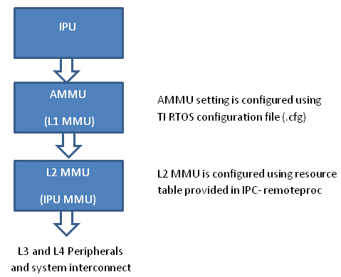
- PDK examples use addresses (0x4X000000) to peripheral registers and
use following MMU setting
- L2 MMU uses default 1:1 Mapping
- AMMU configuration translates physical 0x4X000000 access to logical 0x4X000000
- IPC+ Remote Proc ARM+M4 requires IPU to use logical address
(0x6X000000) and uses following MMU setting
- L2 MMU is configured such that MMU translates 0x6X000000 access to addresss 0x4X000000
- AMMU is configured for 1:1 mapping 0x6X000000 and 0x6X000000
Therefore after integrating IPC with PDK drivers, it is recommended that the alias addresses are used to access peripherals and PRCM registers. This requires changes to the addresses used by PDK drivers and in application code.
The following changes were then made to the IPU application source code:
Add UART_soc.c file to the project and modify the base addresses for all IPU UART register instance in the UART_HwAttrs to use alias addresses:
#ifdef _TMS320C6X
    CSL_DSP_UART3_REGS,
    OSAL_REGINT_INTVEC_EVENT_COMBINER,
#elif defined(__ARM_ARCH_7A__)
    CSL_MPU_UART3_REGS,
    106,
#else
    (CSL_IPU_UART3_REGS + 0x20000000),    //Base Addr = 0x48000000 + 0x20000000 = 0x68000000
    45,
#endif
Adding custom SOC configuration also means that you should use the generic UART driver instead of driver with built in SOC setup. To do this comment the following line in .cfg:
var Uart              = xdc.loadPackage('ti.drv.uart');
//Uart.Settings.socType = socType;
There is also an instance in the application code where we added pointer to PRCM registers that need to be changed as follows.
 CSL_l4per_cm_core_componentRegs *l4PerCmReg =
(CSL_l4per_cm_core_componentRegs *) 0x6a009700; //CSL_MPU_L4PER_CM_CORE_REGS;
Now, you are ready to build the firmware. After the .out is built, change the extension to .xem4 and copy it over to the location in the filesystem that is used to load M4 firmware.