6.4.2. Linux Board Port
6.4.2.1. Overview
This document describes how to conduct a Linux Board Port on an AM335x-type custom board. This process will first start with a base Board Port using a hello_world.dts file, which can then be iteratively changed to add needed peripherals.
This tutorial assumes the latest TI SDK has been installed, and a host machine has been properly configured.
This tutorial also recommends using TI’s hello_world.dts file.
Note
This document outlines steps to conduct a basic Linux Board Port based on a BeagleBone Black (AM335x), but can be adapted to fit any board.
Note
To assist with the port abstraction there is a processor DTSI file that contains node definitions for describing the SOC itself as well as all the peripherals of the selected processor. The DTSI is used as an include file for a custom board DTS file. Typically these DTSI files should be used as is and should not be edited. The main reason is that TI may make peripheral node definition changes during development of an SDK release.
6.4.2.2. Creating an initial baseline “Hello World” Device Tree Source file
In order to conduct a Linux Board Port on a custom board, we must first create an initial baseline to build up from. Once this baseline has been created, we can iteratively add the peripherals necessary for our custom board by including the Device Tree Source file produced by the Pin Mux Tool in our hello_world.dts file.
Note
Although it is possible to use a full board DTS from the start, it is recommended to start from the hello_world.dts file to differentiate between issues related to hardware, and issues related to the DTS file. Starting from a known working hello_world.dts and adding to it is much simpler to debug. Because this guide is based on a TI EVM, it is also recommended to bring up this hello_world.dts on a TI EVM.
Creating a minimal pinmux.dtsi file
Install and open TI’s Pin Mux Tool, which is available in either Windows, Linux, or Cloud formats
Note
More information about using the Pin Mux Tool can be found on TI’s Processor SDK Documentation.
Select your device and package
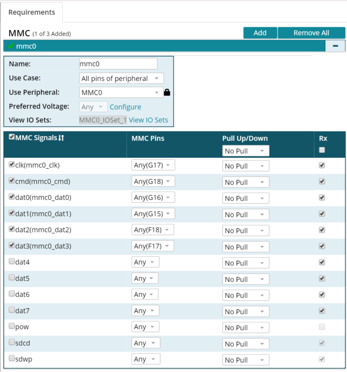
Add a MMC device and set configurations like below:
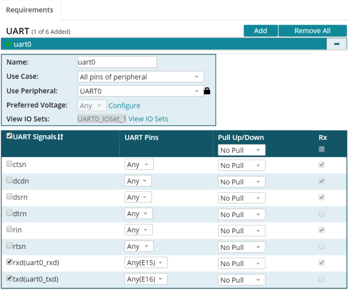
Add a UART device and set configurations like below:
Export the Pin Mux Tool’s generated DTSI file as pinmux.dtsi
Delete all “Optional sleep pin settings” sections from pinmux.dtsi unless necessary. If sleep pin settings are needed, values must be entered manually into pinmux.dtsi
Copy pinmux.dtsi to <PROCESSOR-SDK>/board-support/linux-x.xx.xx+gitAUTOINC+be5389fd85-gbe5389fd85/arch/arm/boot/dts/
Note
MMC and UART are the minimum devices necessary to conduct a minimal Linux board port. More peripherals can be added iteratively in the next section.
Note
Binding peripherals is very important to a successful Linux board port. The included hello_world.dts file has already binded the MMC and UART devices, but binding must be done for each peripheral. Common Bindings can be found here
Building and adding hello_world.dts to SDK Kernel tree directory
Add the line
#include pinmux.dtsiafter#include processor.dtsito hello_world.dtsNavigate to top-level kernel tree in SDK <PROCESSOR-SDK>/board-support/linux-x.xx.xx+gitAUTOINC+be5389fd85-gbe5389fd85
Copy included hello_world.dts file to <PROCESSOR-SDK>/board-support/linux-x.xx.xx+gitAUTOINC+be5389fd85-gbe5389fd85/arch/arm/boot/dts/
Add hello_world.dtb associated with out new hello_world.dts file to the make system by editing arch/arm/boot/dts/Makefile. Make sure to place it in the correct config section. For this example, this line would be placed under the
dtb-$(CONFIG_SOC_AM33XX)block: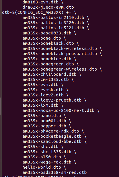
Build hello_world.dts:
make ARCH=arm CROSS_COMPILE='arm-linux-gnueabihf-' mrproper
make ARCH=arm CROSS_COMPILE='arm-linux-gnueabihf-' tisdk_am335x-evm_defconfig
make ARCH=arm CROSS_COMPILE='arm-linux-gnueabihf-' dtbs
Test the minimal Hello World Linux Board Port
Create a bootable SD card by following the steps outlined in the Linux SD Card Creation Guide. It is recommended to follow the steps to create a “SD Card Using Default Images.”
Make a copy of the am335x-boneblack.dtb file in the SD card root file system:
sudo mv /media/<USER>/rootfs/boot/am335x-boneblack.dtb
/media/<USER>/rootfs/boot/am335x-boneblack.dts-orig
Copy the newly built hello_world.dtb file into the rootfs/boot directory of the SD card as am335x-boneblack.dtb:
sudo cp <PATH-TO-FILE>/hello_world.dtb /media/<USER>/rootfs/boot/am335x-boneblack.dtb
Note
Replacing the am335x-boneblack.dtb with our own hello_world.dtb file will allow us to use the prebuilt U-Boot and reduce our workload. Until our custom board ID has been flashed into the EEPROM, using the default BeagleBone Black ID will suffice.
Connect board to serial port via FTDI Cable and boot it from the new SD Card
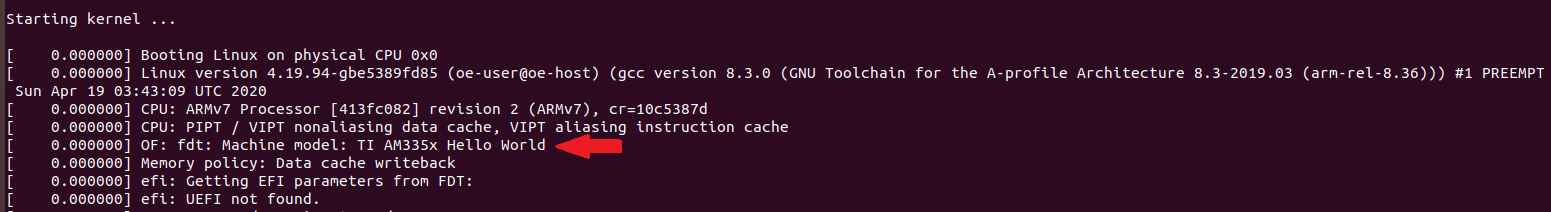
If the minimal Linux board port was successful, the following “Hello World” message should appear:
6.4.2.3. Iteratively Building the PinMux for Custom Board
Now that a minimal “Hello World” Linux board port has been completed in the previous steps, we can now start customizing our board by adding support for the board’s peripherals. We can do this by iteratively adding peripherals one by one to the Device Tree Source. Doing this process iteratively will save time by reducing the number of devices that need to be debugged at once.
To customize your board, the PinMux on your processor needs to be set for your board’s peripherals. TI’s Pin Mux Tool provides a graphical user interface for selecting the peripheral interfaces that will be used in the system design. Its intelligent solver automatically selects pin combinations that help the designer make sure there are no multiplexing conflicts.
Open project from previous steps on TI’s Pin Mux Tool
Add next peripheral needed for your custom board
Export the DTSI file produced by the Pin Mux Tool under the name pinmux.dtsi. This file will be included in your custom board’s hello_world.dts file to provide functionality for all of its peripherals
Copy pinmux.dtsi to <PROCESSOR-SDK>/board-support/linux-x.xx.xx+gitAUTOINC+be5389fd85-gbe5389fd85/arch/arm/boot/dts/
Bind new peripheral to board in hello_world.dts. Common Bindings can be found here
Rebuild hello_world.dts to incorporate the new pinmux.dtsi file:
make ARCH=arm CROSS_COMPILE='arm-linux-gnueabihf-' dtbs
Connect bootable SD card to Linux host and Copy the newly built hello_world.dtb file into the rootfs/boot directory of the SD card as am335x-boneblack.dtb:
sudo cp <PATH-TO-FILE>/hello_world.dtb /media/<USER>/rootfs/boot/am335x-boneblack.dtb
Connect board to serial port via FTDI Cable and boot it from the new SD Card
Correct any errors due to the new peripheral added to pinmux.dtsi
Repeat these steps by adding remaining peripherals to pinmux.dtsi one by one using the Pin Mux Tool
6.4.2.4. Suggested Tips
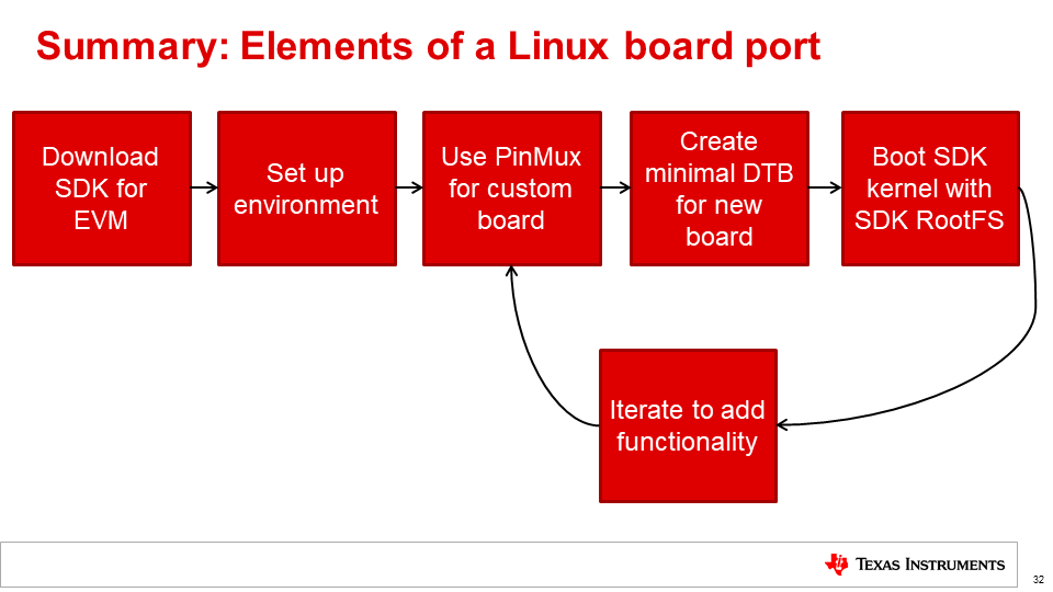
- More information about Linux Board Porting can be found in this Linux Board Port Elements presentation
- The “Hello World” message can be deleted from hello_world.dts once customization and debugging is complete. It is recommended to keep this message until debugging is fully complete to help show if the board port was still successful after changing the pinmux.dtsi file.
- Because this guide is based on a TI EVM, it is suggested to bring up the hello_world.dts on a TI EVM initally.
- Always try to use the TI Pin Mux Tool when adding peripherals. This will limit syntactical errors.