4. Industrial Protocols
4.1. Dual EMAC
4.1.1. Getting Started with PRU-ICSS
Overview
The PRU Software Support Package provides support for the PRU-ICSS Subsystem in AM335x, AM437x, AM57xx, and K2G devices. This package contains:
- Support for ARM<->PRU interaction via remoteproc and rpmsg Linux
drivers
- Remoteproc supports basic control functions such as firmware load, start/halt, simple debug, and interrupt managing
- Rpmsg supports message passing
- Basic firmware examples showing simple functionality
- Register header files for easy register programming
- Library/API for controlling vrings (used for rpmsg)
Things to Obtain
- CCSv7
- PRU Code Generation Tools (you can also get these tools through the CCS App Center)
- ARM running Linux
- Linux Processor SDK for AM335x, Linux Processor SDK for AM437x, Linux Processor SDK for AM57xx, or Linux Processor SDK for K2G
- The PRU Software Support Package is built into the Linux Processor SDK in the ‘<%SDK_INSTALL_DIR%>/example-applications/’ folder
- ARM running RTOS
- RTOS Processor SDK for AM335x, RTOS Processor SDK for AM437x, RTOS Processor SDK for AM57xx, or RTOS Processor SDK for K2G
- PRU Software Support Package - Contains header files and register mappings
Installation of Tools
Tools installation paths are generally fairly arbitrary, but we do have a few requirements once you have installed to your preferred directory.
Linux
- Install Processor SDK to the directory of your choosing Follow the installation instructions found here. Location does not matter, but the default installation directory is strongly suggested and makes using the SDK’s scripts much easier.
- Install the PRU Software Support Package into the SDK you chose above Starting with Linux Processor SDK v2.0.1.7 the support package is built into the SDK at the ‘examples-applications/pru-icss-x.y.z/’ folder
- (Optional) Install CCS to the directory of your choosing CCS installation instruction for Linux can be found here. Makefiles are provided (in addition to CCS projects for most projects) in order to build all examples in the PRU Software Support Package. The ability to build the PRU projects using the Makefiles makes CCS completely optional in a Linux environment.
Windows
- There is no longer a standalone installer for the PRU Software Support Package You must now download the files from the public Git repository here.
- Install CCS to the directory of your choosing Installers can be found here.
How to Enable PRU Support in Kernel
How to Begin Programming
Programming the PRU core is not terribly different from programming any other core. Because we now have a C compiler we are able to write regular C code and have it perform tasks on the PRU cores. A great place to start development is to take a look at the Hands-on Labs that are provided in the PRU Software Support Package.
Register Header Files
Several register header files were created to help facilitate quick and easy configuration. In Linux, these are located in the <SDK_install_dir>/example-applications/pru-icss-x.y.z/include directory by default. In the Git repository these are located in the include folder. See the header files page for more information.
Special Considerations
There are a couple of special CPU registers available with different functionality.
- Writes to R30 control the General Purpose Output pins, and reads allow the user to determine the current state of those pins
- R31 is used to read General Purpose Input pins as well as the status
of the two PRU host interrupts (bits 30 and 31)
- Writes to R31 are used to generate interrupts - see the device-specific TRM for more information on how these work.
What Next?
For support please post questions on the TI E2E forum for Sitara devices.
4.1.2. Header Files
Introduction
The header files for the PRU-ICSS were written in such a way so as to sit on top of the memory-mapped registers. They can be directly linked to that address range via the Linker Command File, but in the existing examples are accessed via the Constant Table registers. The Constant Table is better described here.
Layout
The register sets are grouped up into structures containing the appropriate gaps for reserved registers. Each register can be accessed as a full 32-bit register (although the ECAP peripheral does have some 16-bit registers) or at the bit-field level. This is so as to eliminate the need to do bit-masking at the register level.
Using the Headers
In order to tie the structures to the appropriate Constant Table register we have to use a special trick with the PRU Code Generation Tools package. This process is described in more detail in the CGT Documentation here. For our purposes the linker command file found in each example project contains a “Memory” range for each of the Constant Table entries.
Once this is completed you will be able to access a peripheral register via the structure by accessing that structure’s members. The basic layout is like this:
union{ u32 register_name; struct { bit_field_names : bit_size; . . . } register_name_bit; }; . . . | } register_set;
Thus you can access a register programmatically through the structure (e.g., register_set.register_name[_bit.bitfield_name] = value).
4.1.3. Linux Drivers
4.1.3.1. RemoteProc and RPMsg
Introduction
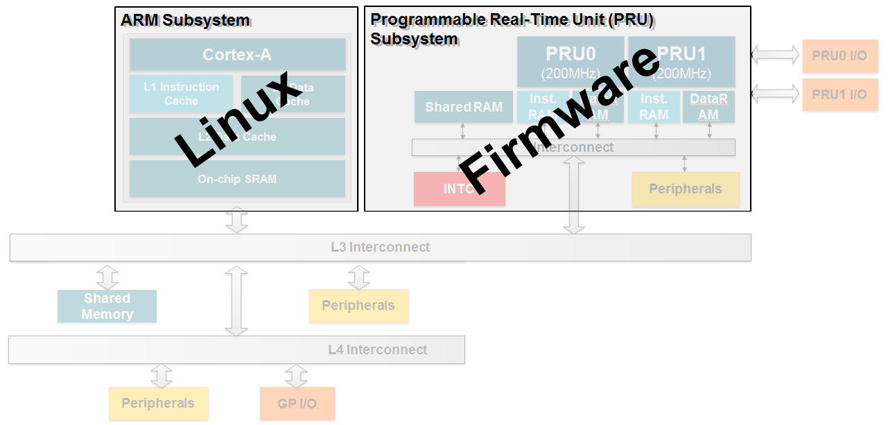
The host processor on TI’s Sitara family of devices is an ARM Cortex-A processor. Typically the ARM core is running Linux based on the Processor SDK. TI has developed custom pruss and pru_rproc (PRU Subsystem Remote Processor) drivers which will plug into this kernel. This provides an interface for the kernel to load firmware into the PRU core(s) and provides basic control such as start and halt. A message passing driver, named rpmsg_pru (remote processor message), has also been developed that allows the PRU and ARM cores to pass messages and buffers back and forth.
What do we need Linux to do?
The following is a list of services that Linux needs to provide in order to enable the PRU cores:
- Load firmware into the PRU cores
- Control PRU execution (start, stop, etc.)
- Manage resources (memory, interrupt mappings, etc.)
- Provide a method to send/receive messages
All of these services are provided through a combination of the pruss, pru_rproc, and rpmsg_pru Linux drivers that TI provides in the Processor SDK.
Remoteproc
Overview
Remoteproc is a framework that allows the ARM host processor(s) to load firmware into PRU cores, start the PRU cores, stop the PRU cores, and configure resources that the PRUs might need during their execution (such as configuring the PRUSS INTC module and providing shared buffers in DDR memory for message passing). The next section will discuss the process that happens when the remoteproc module loads the PRU cores with a firmware. Most of this happens transparently to the user when the pruss and pru_rproc modules are inserted but an understanding of the concepts below should help users to better understand how to debug problems with remoteproc should they arise.
Load Procedure
This section will walk through each step that the drivers takes as they load firmwares into the PRU cores and then run them.
Step 0
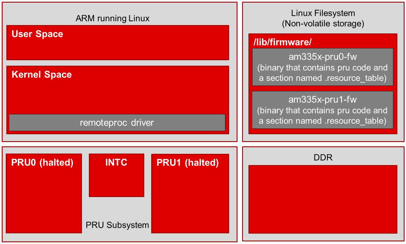
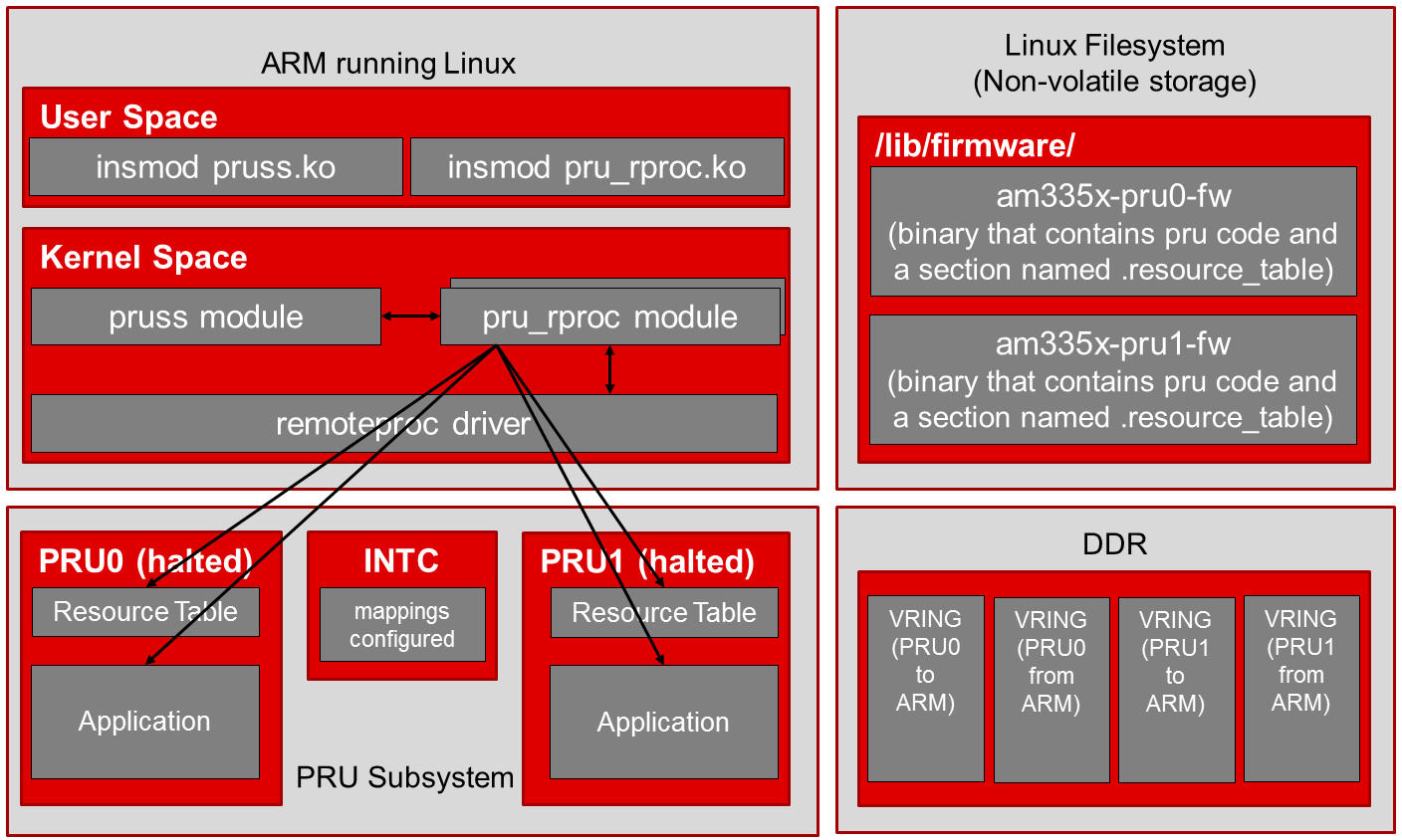
The four blocks in the image to right represent: The ARM core running Linux, the Linux filesystem where the PRU firmware binaries are initially stored, the PRU subsystem, and DDR memory. This image shows the initial state of the system before the pruss_remoteproc module is inserted.
- Remoteproc driver is included as a kernel driver. This is a core remoteproc driver that provides the load/run/halt/etc API to other more specific remoteproc drivers.
- A sysfs interface is also exposed to User Space to start/stop the PRU
cores as well as specify the firmware file to load.
- The sysfs interface is found at /sys/class/remoteproc/remoteprocN/ (e.g. remoteproc1 is PRU0 and remoteproc2 is PRU1 on the AM335x device (remoteproc0 is the M3 core used for power management functions)).
- PRU firmware binaries exist in the filesystem in the /lib/firmware/ directory.
Step 1
Step 2

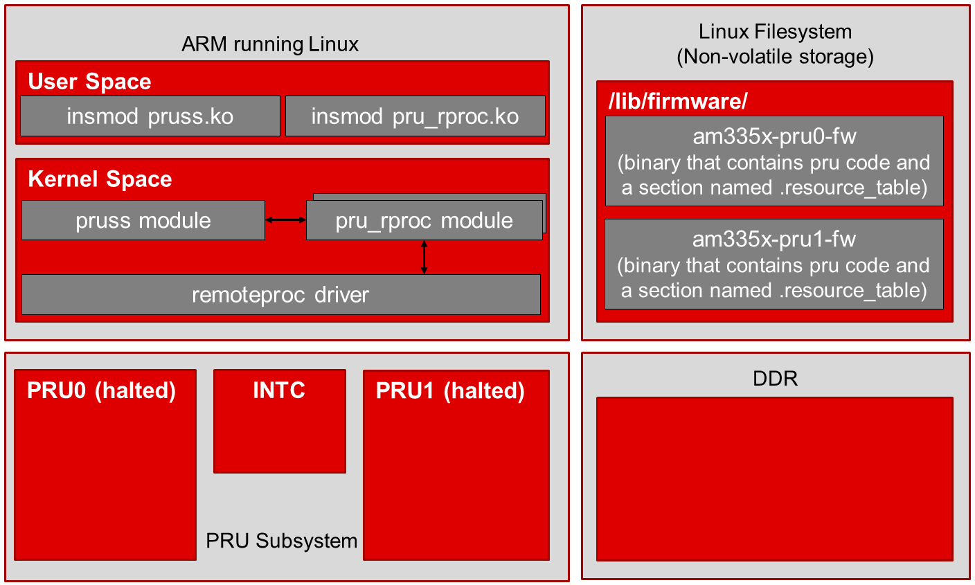
The pru_rproc module verifies two things before it proceeds with the firmware loading process.
- The pru_rproc modules checks for the existence of PRU firmware
binaries in the filesystem (as specified by the firmware entry in the
sysfs in step 1 above)
- These binaries must be located in the /lib/firmware/ directory
- am335x-pru0-fw and am335x-pru1-fw are the default names used for the AM335x device but any name can be used as long as the firmware exists in /lib/firmware/
- The pru_rproc module also parses the firmware binaries looking for a
section named .resource_table
- This .resource_table section of the firmware specifies the system resources that the PRUs will need during their program execution
Step 3
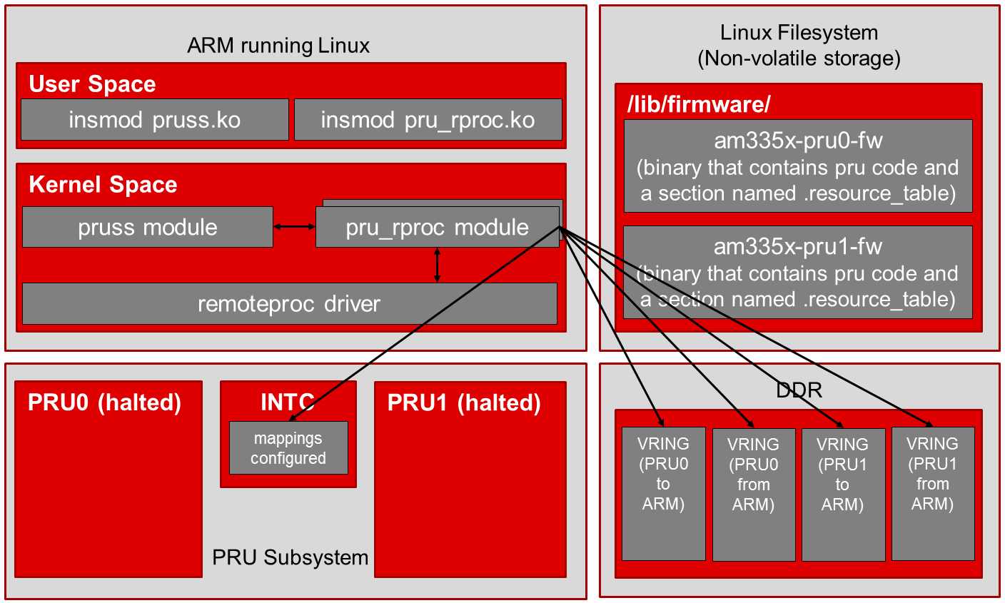
- The pru_rproc module configures all of the resources that are being requested by the firmwares
- In this case, that includes creating vrings in DDR memory for communication as well as setting up the interrupt mapping in the PRU subsystem INTC module
Step 4
Step 5

Now that everything is configured and the application code is in place, the pru_rproc module instructs the PRU cores to begin execution.
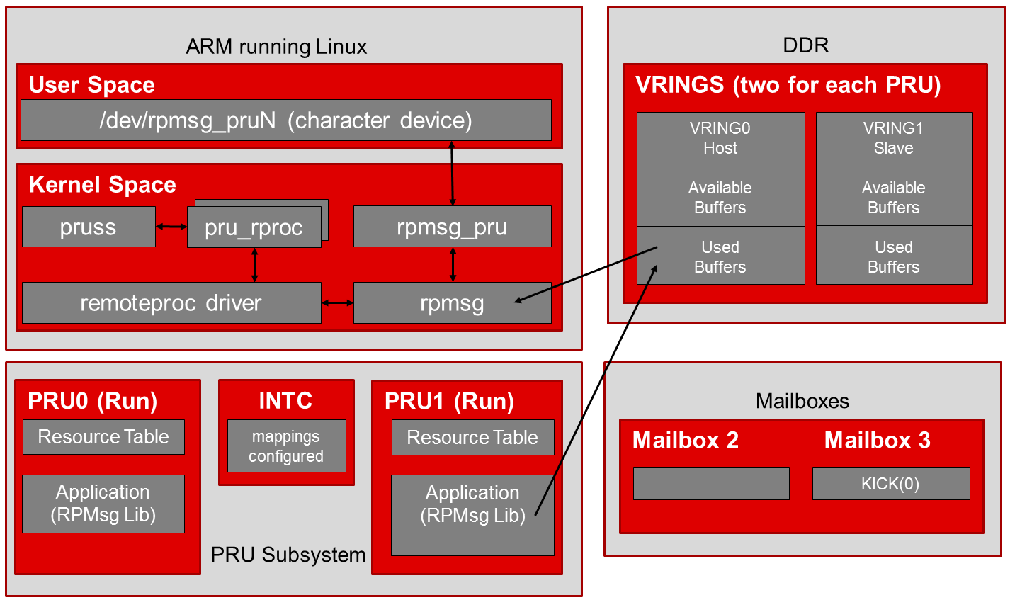
RPMsg
RPMsg is a message passing mechanism that requests resources through remoteproc and builds on top of the virtio framework. Shared buffers are requested through the resource_table and provided by the remoteproc module during PRU firmware loading (as shown in the remoteproc procedure above). The shared buffers are contained inside a vring data structure in DDR memory. There are two vrings provided per PRU core, one vring is used for messages passed to the ARM and the other vring is used for messages received from the ARM. System level mailboxes are used to notify cores (ARM or PRU) when new messages are waiting in the shared buffers.
There are two RPMsg software implementations provided in the Linux Processor SDK. On the ARM Linux side, RPMsg communication is received in kernel space. An interface module is provided (rpmsg_pru) that creates a character device in user space so that users can write/read to/from a character device in the file system to send/receive messages to/from the PRUs. On the PRU side, an RPMsg library is provided in the PRU Software Support Package that aims to abstract the communication to a point where a user’s code can just call the pru_rpmsg_receive and pru_rpmsg_send functions in order to communicate with the ARM core. Source code for the PRU RPMsg library is provided in the support package along with the ability to rebuild the library if changes are desired.
ARM to PRU
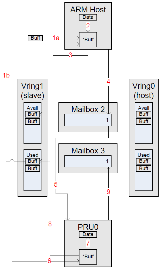
The diagram to the right shows the process that occurs when the ARM sends a message to the PRU. These steps are shown for illustrative purposes as the provided software in the SDK hides them in an abstraction layer.
- ARM Host Steps
- Step 1a: Allocate a new buffer -or-
- Step 1b: Get a Used buffer from the slave Vring
- Step 2: Copy data to be transferred into the buffer from Step 1
- Step 3: Add the newly filled buffer to the Available list in the slave Vring
- Step 4: Kick the slave Vring by writing its index (1) into a message in Mailbox 2
- PRU Steps
- Step 5: A Kick is discovered in Mailbox 2 with the index of the Kicked Vring (1). This indicates to the PRU that data is available for receive
- Step 6: Get the Available buffer from the slave Vring
- Step 7: Copy data to be received out of the buffer from Step 2
- Step 8: Add the now empty buffer to the Used list in the slave Vring
- Step 9: Kick the slave Vring by writing its index (1) into a message in Mailbox 3
PRU to ARM
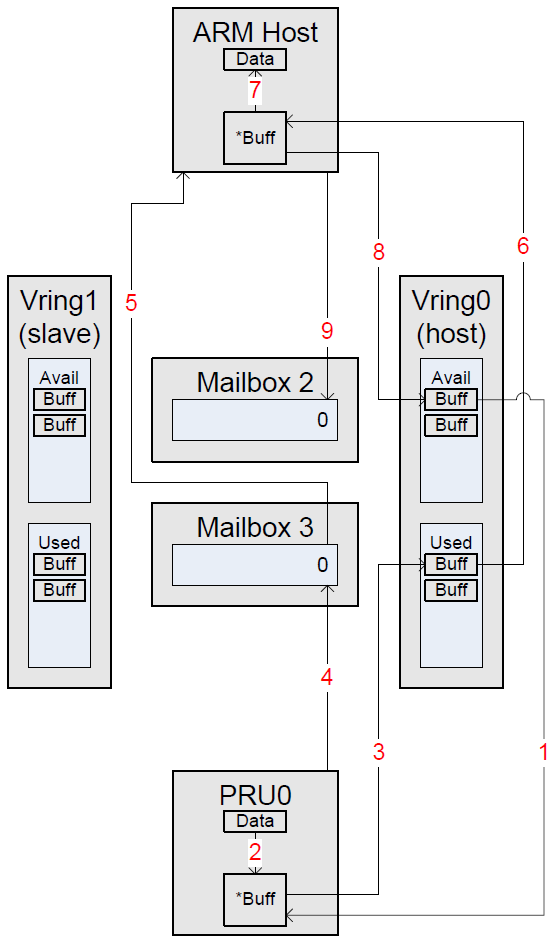
The diagram to the right shows the process that occurs when the PRU sends a message to the ARM. These steps are shown for illustrative purposes as the provided software in the SDK hides them in an abstraction layer.
- PRU Steps
- Step 1: Get an Available buffer from the host Vring
- Step 2: Copy data to be transferred into the buffer from Step 1
- Step 3: Add the newly filled buffer to the Used list in the host Vring
- Step 4: Kick the host Vring by writing its index (0) into a message in Mailbox 3
- ARM Host Steps
- Step 5: An interrupt signals that Mailbox 3 was kicked with the index of Vring (0). This indicates to the ARM Host that data is available for receive
- Step 6: Get the Used buffer from the host Vring
- Step 7: Copy data to be received out of the buffer from Step 2
- Step 8: Add the now empty buffer to the Available list in the host Vring
- Step 9: Kick the host Vring by writing its index (0) into a message in Mailbox 2
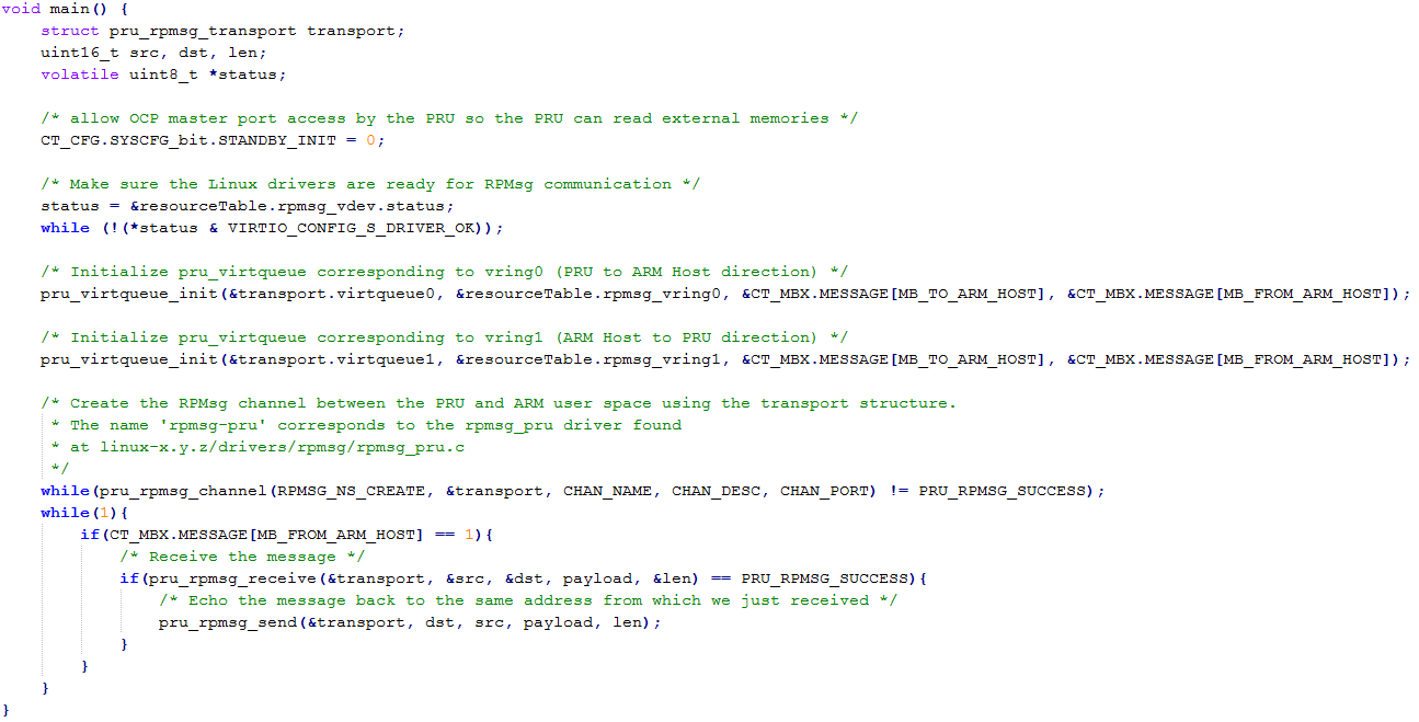
RPMsg PRU Code Example
Next Steps
To get started quickly with remoteproc and RPMsg you can use the RPMsg Quick Start Guide.
For Hands-on Labs that work with the BeagleBone Black and a PRU Cape start here.
4.1.3.2. PRU-ICSS Ethernet
Introduction
As of version 3.1.0.6 of the Linux Processor SDK, the evaluation modules listed below support additional 100 Mbps Ethernet ports through the PRU-ICSS while running Linux as your host operating system.
This page DOES NOT cover any of the industrial protocols that are supported by the PRU-ICSS while running other host operating systems (bare metal, StarterWare, TI RTOS, third party, etc).
For previous versions of the Linux Processor SDK, please see the Archives section at the bottom of this page.
Boards Supported
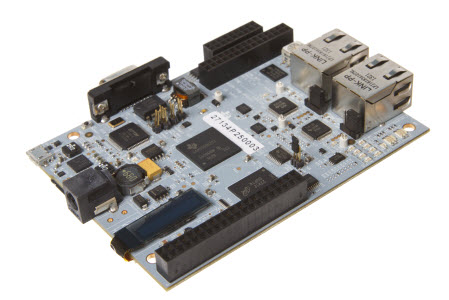
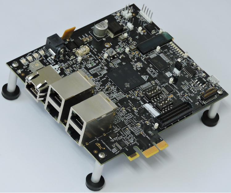
AM3359 Industrial Communications Engine (ICE)
The AM3359 Industrial Communications Engine (ICE) is a development platform targeted for systems that specifically focus on the industrial communications capabilities of the Sitara AM335x ARM® Cortex™-A8 Processors
The AM335x ARM Cortex-A8 Processors integrate the Programmable Real-time Unit (PRU) that has been architected to implement the real-time communication technologies used in a broad range of industrial automation equipment. It enables low foot print designs with minimal external components and with best in class low power performance.
AM437x Industrial Development Kit (IDK)
The AM437x Industrial Development Kit (IDK) is an application development platform for evaluating the industrial communication and control capabilities of Sitara™ AM4379 and AM4377 processors for industrial applications.
The AM4379 and AM4377 processors are ideal for industrial communications, industrial control, and industrial drives applications. The AM437x processors integrate a quad-core Programmable Real-time Unit (PRU) that has been architected to implement the real-time communication technologies used in a broad range of industrial automation equipment. It enables low foot print designs with minimal external components and with best in class low power performance.
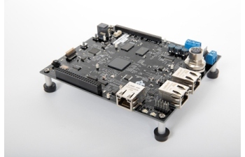
AM571x Industrial Development Kit (IDK)
The AM571x IDK is a standalone test, development, and evaluation module that enables developers to write software and develop hardware for industrial control and industrial communications applications. It has been equipped with a TI AM5718 processor and a defined set of features to allow you to experience industrial communication solutions using various serial or Ethernet based interfaces. Using standard interfaces, the AM571x IDK may interface to other processors or systems and act as a communication gateway or controller. In addition, it can directly operate as a standard remote I/O system or a sensor connected to an industrial communication network.
Note
Due to pin muxing between the optional LCD and the PRUSS1 Ethernet ports, the AM571x IDK supports two configurations. The first configuration is 4-port Ethernet + LCD. In this configuration, two Ethernet ports are provided by the CPSW, two Ethernet ports are provided by PRUSS2, and the LCD is enabled. To use this configuration, place a jumper across J51 on the board. The second configuration is 6-port Ethernet. In this configuration, two Ethernet ports are provided by the CPSW, two Ethernet ports are provided by PRUSS1, two Ethernet ports are provided by PRUSS2, and the LCD is disabled. To use this configuration, leave J51 open.
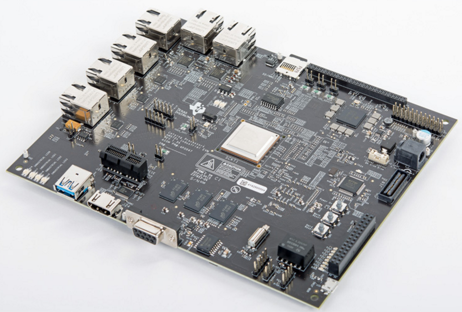
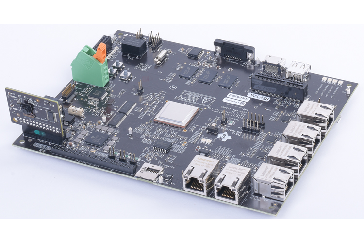
AM572x Industrial Development Kit (IDK)
The AM572x Industrial Development Kit (IDK) is a development platform for evaluating the industrial communication and control capabilities of Sitara AM572x processors for applications in factory automation, drives, robotics, grid infrastructure, and more. AM572x processors include dual PRU-ICSS (Programmable Real-time Unit for Industrial Communications) sub-systems which can be used for industrial Ethernet protocols such as Profinet, EtherCAT, Ethernet/IP, and others. The TMDXIDK5728 breaks out six ports of Ethernet, four of which can be used concurrently: 2x Gb Ethernet ports and 2x 10/100 Ethernet ports from the PRU-ICSS subsystems.
Note
Due to changes in the PRU-ICSS between silicon revisions, the PRU Ethernet firmwares provided for the AM5728 device are only meant to be used on silicon revision SR 2.0.
K2G Industrial Communication Engine (ICE)
The K2G Industrial Communications Engine (ICE) enables 66AK2Gx processor developers to immediately start development, demonstration and test of industrial communication protocols for products such as PLC, bus controllers, motion control and other real-time industrial networked applications. The evaluation module is supported by Processor SDK for RT Linux and TI-RTOS operating systems and is supplied with an SD micro card for easy boot up and out of box experience. The two PRU-ICSS subystems can be used for industrial Ethernet protocols such as Profinet, EtherCAT, Ethernet/IP, and others.
What You Get
With the PRU-ICSS Ethernet support, you get two (or four, on the AM571x IDK and K2G ICE) additional 100 Mbps Ethernet interfaces that show up just like any other Ethernet interface in Linux. These interfaces are there ‘out-of-the-box’ in the latest Linux Processor SDK when ran on any of the boards shown above. All you need to do is plug in an Ethernet cable and bring the interface up from the console (discussed below).
The current implementation does not support Ethernet switching within the PRU-ICSS. The provided PRU firmwares only support ‘dual emac’ mode in this release of the Linux Processor SDK.
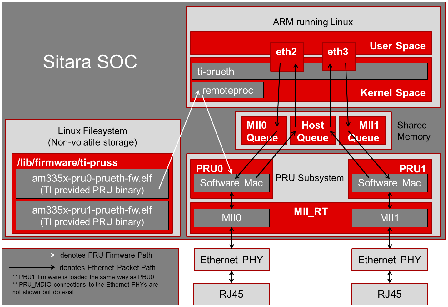
How It Works
Texas Instruments provides all of the necessary software and firmware in the Linux Processor SDK to enable the PRU-ICSS Ethernet ports. The PRU firmware binaries can be found in the /lib/firmware/ti-pruss/ folder in the filesystem. A Linux kernel networking driver is provided that can be found at <%LINUX_PROC_SDK_X_X_X_X%>/board-support/linux-x.y.z..../drivers/net/ethernet/ti/prueth.c. The required device tree modifications are also given in the dts files of the supported boards from above.
As the boards boot, the prussN_eth device tree node causes the ti-prueth driver to be probed. This probe function does several things to prepare the PRU-ICSS Ethernet ports:
- Configures the mux mode of the PRU pins for MII mode
- Requests ownership of the PRUSS memory regions from the pruss driver
- Allocates a pool of memory in OCMC SRAM for the Ethernet buffers to be passed from the PRU to Linux
- Initializes a netdev devices
- Registers the network device with Linux
At this point the Linux driver is ready for the new Ethernet interface to be started. Once the user issues the interface up command (‘ifup eth2’ for example), the emac_ndo_open function is called in the ti-prueth driver which uses the remoteproc interface to boot the PRU cores with the firmware provided in the /lib/firmware/ti-pruss/ folder of the EVM filesystem. The PRUs running this firmware, coupled with the ti-prueth Linux driver, allows up to 2 (or 4, on the AM571x IDK) additional 100 Mbps Ethernet interfaces to be exposed to the user.
Block Diagram
Try It Out
Here are the steps needed to test out the new Ethernet interfaces:
Get your hands on one of the industrial boards
Download the Linux Processor SDK (v3.1.0.6 or higher)
Run the ‘create SD card’ script provided in the SDK to create a bootable SD card
- Plug your SD card into your Ubuntu development machine with a USB card reader
- cd <%LINUX_PROC_SDK_X_X_X_X%>/bin/
- sudo ./create-sdcard.sh
- follow the script directions to format your SD card and then install the pre-built binaries from the SDK
- for more information on creating an SD card: Processor_SDK_Linux_create_SD_card_script
Boot from the newly created SD card
Put the SD card into your board, power it on, and wait for the login prompt then type root to log in.
Note
You’ll need to clear the SPI flash on the AM3359 ICE board before you can boot from an SD card: AM3359 ICE clear SPI flash
Plug an Ethernet cable into the ports supported by the PRU-ICSS
On the AM3359 ICE there are only two Ethernet ports on the board
- In order to use the PRU-ICSS with these ports (instead of the
CPSW) you need to correctly configure both of the jumpers that
are located right next to the RJ45 jacks
- Jumpers J18 and J19 both need to be set to MII to use PRU-ICSS on the ports, you need to reboot the device for jumper changes to take effect
- If you set both of these jumpers to RMII then the CPSW will drive the ports, not the PRU-ICSS
- It is not supported to set the two jumpers to different values. Both need to be MII (PRU-ICSS) or both need to be RMII (CPSW).
- In order to use the PRU-ICSS with these ports (instead of the
CPSW) you need to correctly configure both of the jumpers that
are located right next to the RJ45 jacks
On the AM437x IDK the silkscreen says PRUETH0 and PRUETH1 for the supported PRU ports
On the AM571x IDK the silkscreen says PRU1 ETH0, PRU1 ETH1, PRU2 ETH0, and PRU2 ETH1 for the supported PRU ports
Note
On the AM571x IDK board, the pins used for PRU1 ETH0 and PRU1 ETH1 are shared with pins used for the optional LCD touchscreen. U-Boot uses jumper J51 to determine if the LCD touchscreen should be enabled or not. If J51 is closed (jumper is present across the two pins), then U-Boot will load a device tree that enables the LCD touchscreen and disables PRUSS1 Ethernet ports. This means that only PRU2 ETH0 and PRU2 ETH1 will be supported if jumper J51 is closed. If J51 is open (jumper is not present across the two pins), then U-Boot will load a device tree that enables all four PRUSS Ethernet ports, two from PRUSS1 and two from PRUSS2. In this mode, the LCD touchscreen is disabled.
On the AM572x IDK the silkscreen says PRU2 ETH0 and PRU2 ETH1 for the supported PRU ports
On the K2G ICE the supported PRU ports are the two stacked RJ45 connectors
Bring up the PRU Ethernet interface in Linux
Depending on your board and the contents of your /etc/networking/interfaces file, the PRU-ICSS Ethernet ports may already be brought up. If not:
On the AM3359 ICE type ifup eth0 to bring up Ethernet_0 and type ifup eth1 to bring up Ethernet_1
On the AM437x IDK type ifup eth1 to bring up PRUETH0 and type ifup eth2 to bring up PRUETH1
On the AM571x IDK type ifup eth2 to bring up PRU1 ETH0, type ifup eth3 to bring up PRU1 ETH1, type ifup eth4 to bring up PRU2 ETH0, and type ifup eth5 to bring up PRU2 ETH1
Note
As mentioned in the note above, jumper J51 on the board determines if two or four PRUSS Ethernet ports are supported. If J51 is closed then only two of the four interfaces listed here will be available for use.
On the AM572x IDK type ifup eth2 to bring up PRU2 ETH0 and type ifup eth3 to bring up PRU2 ETH1
On the K2G ICE type ifup eth1, ifup eth2, ifup eth3, and ifup eth4 to bring up the PRU Ethernet interfaces
If all goes well you should see the PRU-ICSS ports in the output of the ifconfig command
Network Topologies
The following network topologies are possible with the PRU-ICSS Ethernet ports.
Single Port Mode
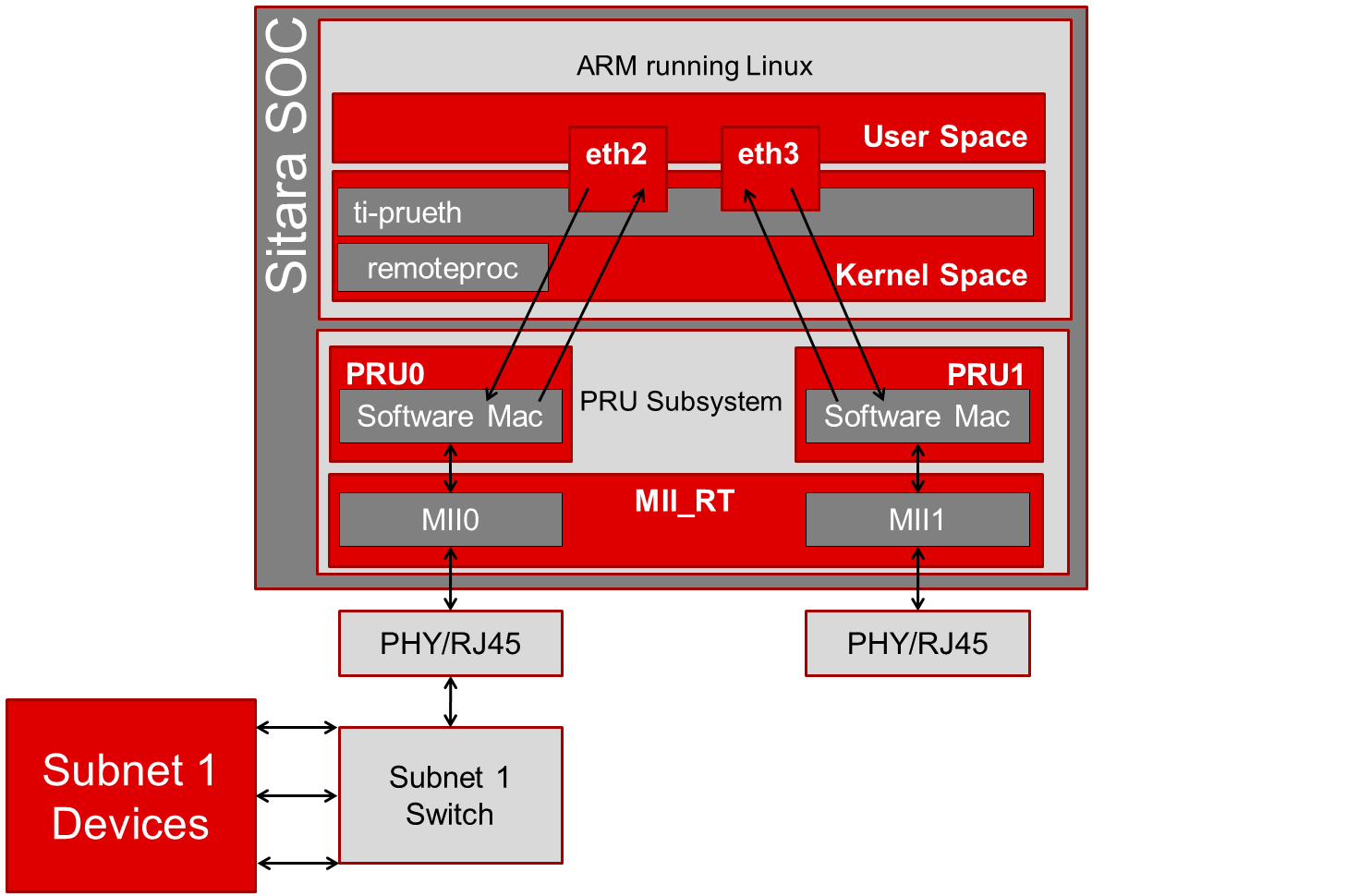
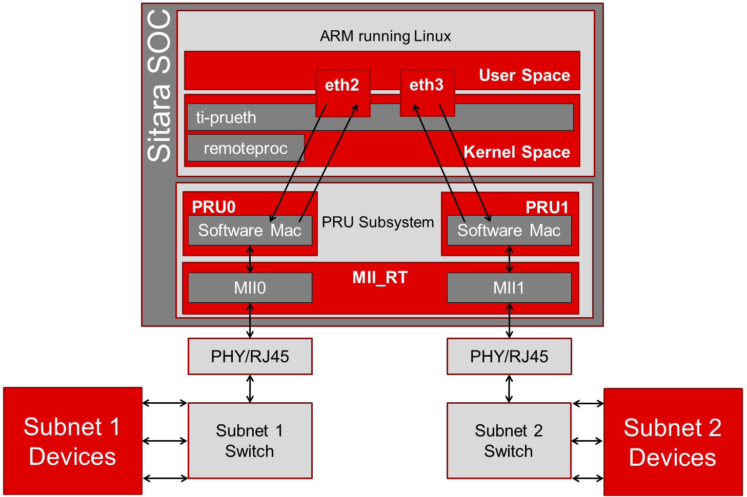
Dual MAC Mode (Gateway)
One use case made possible with two ports on the same device is to allow your device to act as a gateway between two different subnets. In this use case you just need to bring up both ports and then plug them into the two subnets as shown below.
Note
It is not a normal use case to plug both PRU-ICSS Ethernet ports into the same switch (same subnet) out-of-the-box. While it may appear to work at first, it will lead to unexpected behavior including (but not limited to) packets entering/exiting the device on the opposite port that you would expect due to ARP broadcasts and other topics that are outside the scope of this wiki page. If you would like to use both ports on the same subnet, keep scrolling to the Bonding section below.
Dual MAC Mode (Bonding)
Bonding, also called link aggregation or port trunking, is a networking feature that uses multiple Ethernet ports to provide link redundancy or an increase in throughput.
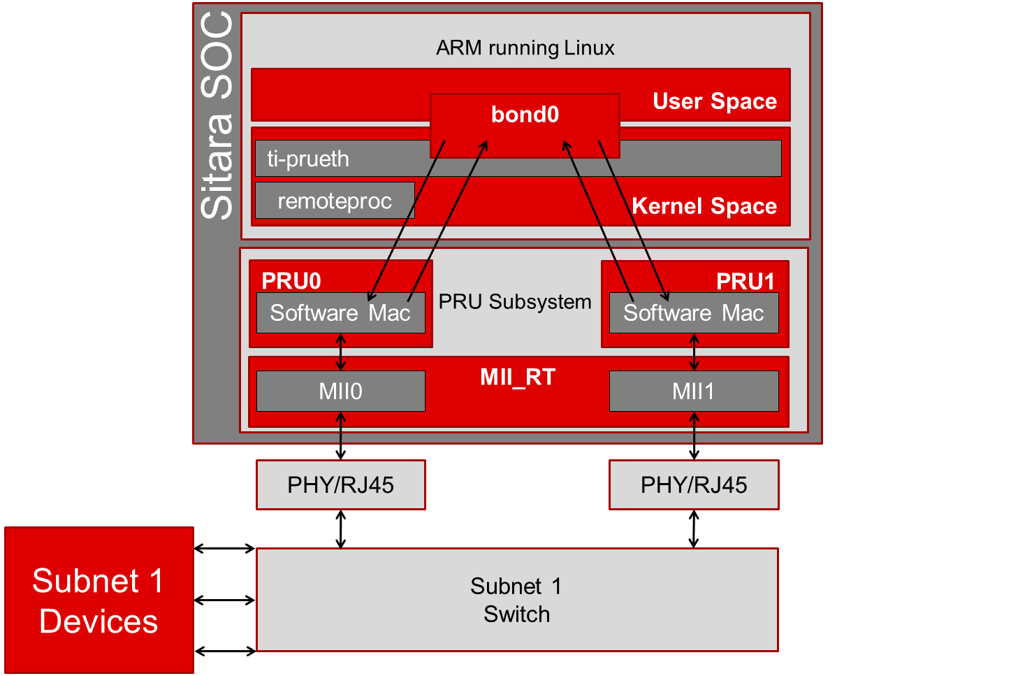
To learn even more about bonding see the Wikipedia Link aggregation page.
Steps to enable ‘active-backup’ bonding mode
While testing the below steps, I plugged both PRU-ICSS Ethernet ports into the same switch that has access to a DHCP server. During boot and bonding setup I left the cables connected. I only started unplugging cables when I was testing the bond0 interface for redundancy in the last step.
On your Linux development machine
- Enable Bonding driver support using menuconfig, rebuild Linux,
and boot your board
- The menuconfig option can be found under Device Drivers -> Network device support -> Bonding driver support’
- You can either configure the driver as built-in to the kernel (*) or as a module (M). Keep in mind that if you build the driver into the kernel that you will not be able to pass any parameters to it as it is loaded. For the example shown here, we will be using the sysfs interface to configure the bonding so it doesn’t matter which method you choose (we used the module (M) method though).
- Once Bonding driver support is enabled, rebuild your Linux
kernel and modules
- If you need help, see this page: Linux_Kernel_Users_Guide
- Now boot your board with the new kernel and bonding driver built above
On your development board console
Insert the bonding module (unless you built it into the kernel above, then it’s already there)
- modprobe bonding
Get the IP address and netmask of one of your PRU-ICSS Ethernet ports (we will need it in a second)
If the ports are already up
- ifconfig
If the ports are not up yet
ifup eth2 where 2 is the interface number for one of your PRU-ICSS Ethernet ports (this is board dependent)
ifconfig
Note
AM3359ICE: eth0 and eth1 are the PRU-ICSS Ethernet ports
AM437x IDK: eth1 and eth2 are the PRU-ICSS Ethernet ports
AM572x IDK: eth2 and eth3 are the PRU-ICSS Ethernet ports
Take down your PRU-ICSS Ethernet ports (this is necesary for bonding)
- ifconfig eth2 down
- ifconfig eth3 down
Configure bonding to use mode 1: active-backup mode
- echo 1 > /sys/class/net/bond0/bonding/mode
Configure the MII link monitoring frequency in milliseconds
- echo 100 > /sys/class/net/bond0/bonding/miimon
Bring up the bond0 interface using the IP address and netmask that you noted down from above
- ifconfig bond0 192.168.0.100 netmask 255.255.254.0 up
Bind your two PRU-ICSS Ethernet ports to the bond0 interface
- echo +eth2 > /sys/class/net/bond0/bonding/slaves
- echo +eth3 > /sys/class/net/bond0/bonding/slaves
Test out the link redundancy of the bond0 interface
- Start a ping test between your board and your development machine
- Watch the board’s console and unplug one of the Ethernet cables
- Now plug that cable back in and unplug the other Ethernet cable
- You should observe the ping program continuously receiving responses despite the cables being plugged and unplugged
- The console output will show when an interface goes does down as well as if the active interface changes
Frequently Asked Questions
Are the HSR or PRP protocols supported?
Yes! The HSR and PRP protocols are currently supported on the AM572x IDK board. To learn more about the HSR and PRP PRU firmware implementation click here. To learn more about running the protocols/firmwares while using the Linux Processor SDK click here.
HSR stands for High Availability Seamless Redundancy. This is a protocol used to support redundant networks needed for industrial applications such as factory automation, substation automation etc. The standard is defined in IEC 62439-3 clause 5.
PRP stands for Parallel Redundancy Protocol which is another redundancy protocol defined by IEC 62439-3 clause 4.
I am using the AM571x IDK, why do I only see 4 Ethernet interfaces instead of 6?
Due to pin sharing between the optional LCD and the PRUSS1 Ethernet pins, the AM571x IDK supports two different configurations: 4-port Ethernet + LCD or 6-port Ethernet with no LCD. Jumper J51 controls which configuration is selected. If J51 is closed then the 4-port + LCD configuration is selected and if J51 is open then the 6-port Ethernet configuration is selected and the LCD is disabled.
What if I want the PRU-ICSS to run a custom firmware (not Ethernet) on one of these industrial boards?
The pru_rproc driver uses the of_machine_is_compatible() function to check if the device that it is running on is compatible with one of the boards above. If it is compatible, then the pru_rproc driver loads the Texas Instruments provided PRU-ICSS Ethernet firmwares. If you would like to run your own PRU firmwares on one of the IDKs or the ICE board then you will need to modify the device tree file to remove the IDK or ICE compatibility declaration:
- AM3359 ICE board
- Remove the “ti,am3359-icev2” compatible declaration at the top of the arch/arm/boot/dts/am335x-icev2.dts file
- AM437x IDK board
- Remove the “ti,am437x-idk-evm” compatible declaration at the top of the arch/arm/boot/dts/am437x-idk-evm.dts file
- AM572x IDK board
- Remove the “ti,am5718-idk” compatible declaration at the top of the arch/arm/boot/dts/am571x-idk.dts file
- AM572x IDK board
- Remove the “ti,am5728-idk” compatible declaration at the top of the arch/arm/boot/dts/am572x-idk.dts file
Once these compatibility declarations are removed you will need to rebuild your .dtb file and place it wherever it needs to be when you reboot your board (filesystem, nfs directory, tftp directory, etc.)
Keep in mind that the PRU pin muxing on these boards is configured to bring the MII pins out of the device. Changing the pin muxing to accommodate your custom PRU firmware will be left as an exercise for the user.
What is the expected PRU-ICSS Ethernet throughput? How can I test the throughput on my setup?
The maximum bandwidth of the PRU-ICSS Ethernet ports is 100 Mbps. The observed throughput that I have achieved consistently is around 94 Mbps using TCP or UDP and testing with iperf. Here are the commands needed to test for yourself (this assumes you’ve followed the steps on this page to get your PRU-ICSS interface up and running already):
- Make sure that your board and your Linux development machine can ‘see’ each other on the network (I connect both to the same switch and allow them to use DHCP to acquire IP addresses on the same network)
- Use ifconfig on both your Linux development machine and your
board and note down each IP address
- For the purposes of this example I will use 192.168.0.105 as the Linux host IP and 192.168.1.110 as the board’s IP
- Testing TCP transmit throughput
- Start an iperf server on your Linux development machine (sudo
apt-get install iperf if you don’t already have iperf installed)
- iperf -s
- Run the iperf client from your board to connect to the iperf
server you just started
- iperf -c 192.168.0.105
- You should see your board connect to the server and a few seconds
later both the server and the client will output the Bandwidth
achieved
- For me this is output is around 94 Mbits/sec
- Quit the iperf server that is running on your Linux development
machine
- Ctrl + c
- Start an iperf server on your Linux development machine (sudo
apt-get install iperf if you don’t already have iperf installed)
- Testing TCP receive throughput
- Use the same procedure as provided for testing TCP transmit throughput except swap the commands on the two devices (iperf -s from the board and iperf -c 192.168.1.110 from the Linux development machine)
- Testing UDP transmit throughput
- Start a UDP iperf server on your Linux development machine
- iperf -s -u
- Run a UDP iperf client from your board and specify the bandwidth
you’d like to achieve
- iperf -c 192.168.0.105 -u -b 100M
- Once again my results are around 94 Mbit/sec
- Quit the iperf server that is running on your Linux development
machine
- Ctrl + c
- Start a UDP iperf server on your Linux development machine
- Testing UDP receive throughput
- Use the same procedure as provided for testing UDP transmit throughput except swap the commands on the two devices (iperf -s -u from the board and iperf -c 192.168.0.110 -u -b 100M from the Linux development machine)
Is flow control supported in the PRU-ICSS Ethernet ports?
How do I check the link status and hardware statistics of my PRU-ICSS Ethernet ports?
You can use the ethtool utility:
- ethtool eth2 (for link status)
- ethtool -S eth2 (for hardware statistics)
4.1.4. Linux User Space Drivers and Application
Overview
The ICSS_EMAC (Industrial Communications SubSystem Ethernet Media Access Controller) driver provides APIs to transmit and receive packets with a firmware based Ethernet switch that has been implemented on TI’s PRU-ICSS (Programmable Real-Time Unit Subsystem and Industrial Communication SubSystem) 32-bit RISC cores. The user space ICSS-EMAC driver has the same software architecture and features as the RTOS ICSS-EMAC, but implements the memory access and interrupt handling through Linux Userspace I/O (UIO) driver.
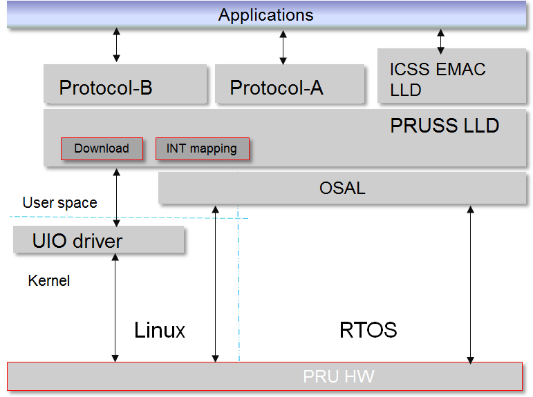
Software Stack
The picture below illustrates the software stack of ICSS-EMAC Linux user space. Majority of the upper layer components are common between RTOS and Linux user space, with the difference on Linux OS with the UIO driver vs. RTOS.
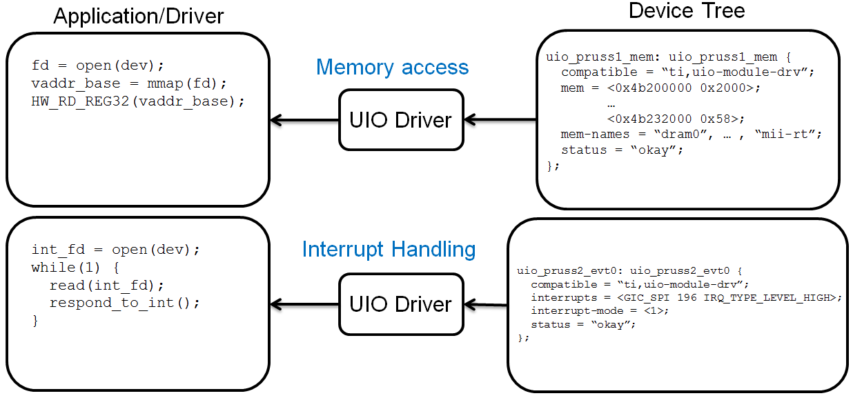
Memory Access and Interrupt Handling through UIO
While RTOS can directly access memory locations, e.g., HW_RD_REG32(0x4b220000), Linux needs memory mapping of memory regions to user space, and this is done using the UIO driver with linux file-I/O like API such as open(), close(), read(), write(), and etc.
As for the interrupt handling, RTOS registers interrupt service routines (ISRs) that are triggered when an interrupt occurs, while Linux must have a thread that waits (read()) on the file descriptor for an interrupt. Device interrupts are accessed from Linux user-space, and linux file-I/O like API such as open(), close(), read(), write(), and etc. are used here also.
The picture below shows how the memory regions and interrupts are defined in kernel device tree, and how the application/driver can map and access the memory regions, as well as handle the interrupts through the UIO driver.
Rebuild ICSS-EMAC in Linux User Space
Processor SDK Linux has packaged the pre-built binary for ICSS-EMAC LLD unit test, which can be found on filesystem at /usr/bin/icss_emacMainTest_[platform].out.
The source code of the ICSS-EMAC LLD and the unit test can be found at https://git.ti.com/keystone-rtos/icss-emac. The changes specific to Linux user space can be found by looking for the define of “__LINUX_USER_SPACE”. The files to implement the UIO based memory access and interrupt handling are placed under the test/src/armv7/linux directory.
When there is need to modify the source code of the ICSS-EMAC LLD and/or the unit test, the LLD and the unit test can be rebuilt through Yocto recipes. In order to do so, please refer to Processor SDK Building The SDK to set up the build environment, and Processor SDK Yocto Recipes to bitbake the recipes and install the newly built packages for icss-emac-lld and icss-emac-lld-test.
For example, the commands below are for rebuilding icss-emac-lld and icss-emac-lld-test for AM57xx.
MACHINE=am57xx-evm bitbake icss-emac-lld
MACHINE=am57xx-evm bitbake icss-emac-lld-test
After the bitbake commands above are successfully done, the icss-emac-lld lib and the icss-emac-lld-test binaries can found from ./build/arago-tmp-external-linaro-toolchain/work/am57xx_evm-linux-gnueabi/icss-emac-lld/<ver_number>/packages-split/icss-emac-lld/usr/lib and ./build/arago-tmp-external-linaro-toolchain/work/am57xx_evm-linux-gnueabi/icss-emac-lld-test/<ver_number>/packages-split/icss-emac-lld-test/usr/bin directories, respectively.
Running ICSS-EMAC Unit Test in Linux User Space
ICSS-EMAC unit test demonstrates loopback capability by sending dummy broadcast packets, which are then looped back with loopback cables. Unit test registers receive packet callback routine with LLD to be called for RX packet. Call back routine will extract packet received, perform simple memory comparison against packet sent for integrity check. Unit test will iterate 10 times for packet transmission and reception check. It also demonstrates time trigger send (TTS) after broadcast packets send/receive are completed. At the end of unit test, “All tests have passed” will be printed on console.
Note
Please note that time trigger send (TTS) is supported for PROCESSOR-SDK-LINUX-RT builds only due to its real-time requirement. Running TTS with PROCESSOR-SDK-LINUX builds can fail with “Packet cyclic timestamp error”.
ICSS-EMAC user space driver and unit test are now supported on multiple TI platforms, including
- AM335x ICE V2
- AM437x IDK
- AM571x IDK
- AM572x IDK
- K2G ICE
The sections below describe the procedure and sample logs of running the ICSS-EMAC unit test on these platforms.
AM335x ICE V2
Before powering up the AM335x ICE V2 EVM, ensure that Pin 2 and Pin 3 of the two CPSW/ICSS Jumpers are connected. Location of these two jumpers can be found from https://processors.wiki.ti.com/index.php/AM335x_Industrial_Communication_Engine_EVM_Rev2_1_HW_User_Guide#Component_Positions.
- Plug in loopback cables to the two ICSS-EMAC ports of AM335x ICEv2 EVM
- On the filesystem under /boot directory, link am335x-icev2-pru-excl-uio.dtb as the default dtb file, i.e., am335x-icev2.dtb.
- Reboot the EVM
- Run “icss_emacMainTest_am335x.out”
AM437x IDK
- Plug in loopback cables to the two ICSS-EMAC ports of AM4 IDK EVM
- On the filesystem under /boot directory, link am437x-idk-pru-excl-uio.dtb as the default dtb file, i.e., am437x-idk-evm.dtb
- Reboot the EVM
- Run “icss_emacMainTest_am437x.out”
AM571x IDK
First ensure that Jumper J51 is not placed. That selects between LCD function (J51 placed) and ICSS1 Ethernet (J51 removed). This also indicates that ICSS-EMAC unit test cannot run with LCD connected on the AM571x IDK board.
- Plug in four loopback cables to the four ICSS-EMAC ports
- On the filesystem under /boot directory, link am571x-idk-pru-excl-uio.dtb as the default dtb file, e.g., am571x-idk.dtb when using AM571x IDK without LCD display
- Reboot the EVM
- Run “icss_emacMainTest_am571x.out”
AM572x IDK
- Reserve core 1 for the unit test, and this can be done by adding “isolcpus=1” in uEnv.txt (under boot partition).
- On the filesystem under /boot directory, link am572x-idk-pru-excl-uio.dtb as the default dtb file, e.g., am572x-idk.dtb.
- Reboot the EVM.
- Before running the unit test, open an SSH window to the EVM.
- From console 1: run “icss_emacMainTest_am572x.out”. It will display a message and wait for the keyboard input.
- From console 2: set affinity of the unit test process to core 1: first find pid from the output log of “ps aux | grep icss”, and then run “taskset -p 2 [pid]”.
- From console 1: continue running “icss_emacMainTest_am572x.out” by pressing any keys.
K2G ICE
- Plug in loopback cables to the four ICSS-EMAC ports of K2G ICE EVM
- On the filesystem under /boot directory, link keystone-k2g-ice-pru-excl-uio.dtb as the default dtb file, i.e., keystone-k2g-ice.dtb
- Reboot the EVM
- Run “icss_emacMainTest_k2g.out”
Sample Log from AM572x IDK
- Console 1
root@am57xx-evm:~# icss_emacMainTest_am572x.out
Set core affinity before continuing the process: taskset -p 2 [pid]
Enter character:
- Console 2
root@am57xx-evm:~# ps aux | grep icss
root      1425  0.0  0.0   1472  1068 ttyS2    S+   18:24   0:00 icss_emacMainTest_am572x.out
root      1427  0.0  0.0   1968  1100 pts/0    S+   18:30   0:00 grep icss
root@am57xx-evm:~# taskset -p 2 1425
pid 1425's current affinity mask: 3
pid 1425's new affinity mask: 2
- Console 1 after hitting any key to continue the test:
ICSS_EMAC_testTaskPruss2: ICSS_EMAC_testPgVersion: 0x2
ICSS_EMAC_testTaskPruss2: PRU2 ETH0: LINK IS UP, eth0 state: 1, link up count: 1
packet transmission complete for packet(ICSS_EMAC_TEST_PRU2ETH0): 0
ICSS_EMAC_testTaskPruss1(PRU2 ETH0): received pkt: 0
packet transmission complete for packet(ICSS_EMAC_TEST_PRU2ETH0): 1
ICSS_EMAC_testTaskPruss1(PRU2 ETH0): received pkt: 1
packet transmission complete for packet(ICSS_EMAC_TEST_PRU2ETH0): 2
ICSS_EMAC_testTaskPruss1(PRU2 ETH0): received pkt: 2
ICSS_EMAC_testTaskPruss1(PRU2 ETH0): received pkt: 3
packet transmission complete for packet(ICSS_EMAC_TEST_PRU2ETH0): 3
ICSS_EMAC_testTaskPruss1(PRU2 ETH0): received pkt: 4
packet transmission complete for packet(ICSS_EMAC_TEST_PRU2ETH0): 4
ICSS_EMAC_testTaskPruss1(PRU2 ETH0): received pkt: 5
packet transmission complete for packet(ICSS_EMAC_TEST_PRU2ETH0): 5
ICSS_EMAC_testTaskPruss1(PRU2 ETH0): received pkt: 6
packet transmission complete for packet(ICSS_EMAC_TEST_PRU2ETH0): 6
packet transmission complete for packet(ICSS_EMAC_TEST_PRU2ETH0): 7
ICSS_EMAC_testTaskPruss1(PRU2 ETH0): received pkt: 7
packet transmission complete for packet(ICSS_EMAC_TEST_PRU2ETH0): 8
ICSS_EMAC_testTaskPruss1(PRU2 ETH0): received pkt: 8
packet transmission complete for packet(ICSS_EMAC_TEST_PRU2ETH0): 9
ICSS_EMAC_testTaskPruss1(PRU2 ETH0): received pkt: 9
ICSS_EMAC_testTaskPruss2: PRU2 ETH1: LINK IS UP, eth0 state: 1, link up count: 2
packet transmission complete for packet(ICSS_EMAC_TEST_PRU2ETH1): 0
ICSS_EMAC_testTaskPruss1(PRU2 ETH1): received pkt: 10
packet transmission complete for packet(ICSS_EMAC_TEST_PRU2ETH1): 1
ICSS_EMAC_testTaskPruss1(PRU2 ETH1): received pkt: 11
packet transmission complete for packet(ICSS_EMAC_TEST_PRU2ETH1): 2
ICSS_EMAC_testTaskPruss1(PRU2 ETH1): received pkt: 12
ICSS_EMAC_testTaskPruss1(PRU2 ETH1): received pkt: 13
packet transmission complete for packet(ICSS_EMAC_TEST_PRU2ETH1): 3
ICSS_EMAC_testTaskPruss1(PRU2 ETH1): received pkt: 14
packet transmission complete for packet(ICSS_EMAC_TEST_PRU2ETH1): 4
ICSS_EMAC_testTaskPruss1(PRU2 ETH1): received pkt: 15
packet transmission complete for packet(ICSS_EMAC_TEST_PRU2ETH1): 5
ICSS_EMAC_testTaskPruss1(PRU2 ETH1): received pkt: 16
packet transmission complete for packet(ICSS_EMAC_TEST_PRU2ETH1): 6
packet transmission complete for packet(ICSS_EMAC_TEST_PRU2ETH1): 7
ICSS_EMAC_testTaskPruss1(PRU2 ETH1): received pkt: 17
packet transmission complete for packet(ICSS_EMAC_TEST_PRU2ETH1): 8
ICSS_EMAC_testTaskPruss1(PRU2 ETH1): received pkt: 18
packet transmission complete for packet(ICSS_EMAC_TEST_PRU2ETH1): 9
ICSS_EMAC_testTaskPruss1(PRU2 ETH1): received pkt: 19

============================================================
Initiating TTS tests on ICSS_EMAC_TEST_PRU2ETH0 and ICSS_EMAC_TEST_PRU2ETH1
============================================================
TTS Port 1: Test Passed!!
Programmed Cycle Period: 800000 ns
Average Cycle Period: 799999 ns
Maximum Jitter: 40 ns
============================================================
TTS Port 2: Test Passed!!
Programmed Cycle Period: 800000 ns
Average Cycle Period: 799999 ns
Maximum Jitter: 40 ns
============================================================
TTS Port 1: Test Passed!!
Programmed Cycle Period: 800000 ns
Average Cycle Period: 800000 ns
Maximum Jitter: 40 ns
============================================================
TTS Port 2: Test Passed!!
Programmed Cycle Period: 800000 ns
Average Cycle Period: 799999 ns
Maximum Jitter: 40 ns
============================================================
TTS Port 1: Test Passed!!
Programmed Cycle Period: 800000 ns
Average Cycle Period: 799999 ns
Maximum Jitter: 40 ns
============================================================
TTS Port 2: Test Passed!!
Programmed Cycle Period: 800000 ns
Average Cycle Period: 799999 ns
Maximum Jitter: 40 ns
============================================================
TTS Port 1: Test Passed!!
Programmed Cycle Period: 800000 ns
Average Cycle Period: 800000 ns
Maximum Jitter: 40 ns
============================================================
TTS Port 2: Test Passed!!
Programmed Cycle Period: 800000 ns
Average Cycle Period: 800000 ns
Maximum Jitter: 40 ns
============================================================
TTS tests finished on ICSS_EMAC_TEST_PRU2ETH0 and ICSS_EMAC_TEST_PRU2ETH1
============================================================
Done with PRU-ICSS Instance 2 Testing

PRU-ICSS STATS for PRU2ETH0
txBcast:0xa
txMcast:0x18a88
txUcast:0x0
txOctets:0x789d80
rxBcast:0xa
rxMcast:0x18a88
rxUcast:0x0
rxOctets:0x789d80
tx64byte:0x186aa
tx65_127byte:0x0
tx128_255byte:0x0
tx512_1023byte:0x0
tx1024byte:0x3e8
rx64byte:0x186aa
rx65_127byte:0x0
rx128_255byte:0x0
rx512_1023byte:0x0
rx1024byte:0x3e8
lateColl:0x0
singleColl:0x0
multiColl:0x0
excessColl:0x0
rxMisAlignmentFrames:0x0
stormPrevCounter:0x0
macRxError:0x0
SFDError:0x0
defTx:0x0
macTxError:0x0
rxOverSizedFrames:0x0
rxUnderSizedFrames:0x0
rxCRCFrames:0x0
droppedPackets:0x0
txOverFlow:0x0
txUnderFlow:0x0
sqeTestError:0x0
TXqueueLevel:0x0
CSError:0x0


PRU-ICSS STATS for PRU2ETH1
txBcast:0xa
txMcast:0x18a88
txUcast:0x0
txOctets:0x789d80
rxBcast:0xa
rxMcast:0x18a88
rxUcast:0x0
rxOctets:0x789d80
tx64byte:0x186aa
tx65_127byte:0x0
tx128_255byte:0x0
tx512_1023byte:0x0
tx1024byte:0x3e8
rx64byte:0x186aa
rx65_127byte:0x0
rx128_255byte:0x0
rx512_1023byte:0x0
rx1024byte:0x3e8
lateColl:0x0
singleColl:0x0
multiColl:0x0
excessColl:0x0
rxMisAlignmentFrames:0x0
stormPrevCounter:0x0
macRxError:0x0
SFDError:0x0
defTx:0x0
macTxError:0x0
rxOverSizedFrames:0x0
rxUnderSizedFrames:0x0
rxCRCFrames:0x0
droppedPackets:0x0
txOverFlow:0x0
txUnderFlow:0x0
sqeTestError:0x0
TXqueueLevel:0x0
CSError:0x0

All tests have passed
4.2. HSR_PRP
4.2.1. Protocol Overview
HSR stands for High Availability Seamless Redundancy. This is a protocol used to support redundant networks needed for industrial applications such as factory automation, substation automation etc. The standard is defined in IEC 62439-3 clause 5. HSR Ethernet frames are not compatible with standard Ethernet frames. HSR frames are identified uniquely by the HSR tag. So only HSR frames are possible in the network which is not identifiable by a standard Ethernet device. Factory or field devices are connected to a Double Attached Node HSR (DANH). Typically these nodes are connected in a Ring topology and only DANH compliant nodes can be connected to the HSR network. Other standard Ethernet devices (Singly Attached Nodes, SANs) needs to be connected through a Redundancy Box (RedBox) to work with HSR networks. HSR tag is used to manage redundancy in HSR network.
A DANH node has two ports operated in parallel. A source DANH prefixes a frame passed from its upper layers with an HSR tag to identify frame duplicates and sends the frame over each port.
A destination DANH receives, in the fault-free state, two identical frames (one from each port) within a certain interval. It removes the HSR tag of the first frame before passing it to its upper layers and discards any duplicate. The nodes support the IEEE 802.1D bridge functionality and forward frames from one port to the other, except if they already sent the same frame in that same direction. In particular, the node will not forward a frame that it injected into the ring.
4.2.2. ICSS Firmware
A common firmware is used across TI RTOS and Linux implementations of HSR/PRP. This section describes the firmware details.
4.2.2.1. Firmware Features Supported
- HSR/PRP
- The implementation is as per IEC 62439-3 Ed 2.0
- Operates as a DAN (Dual Attached Node)
- HSR
- Operates as a DANH
- As per clause 5 of the standard
- Support for modes – H, T, U and N as per standard
- Modes can be changed at run time
- PRP
- Operates as a DANP
- As per clause 6 of the standard
- Two ports as per standard, Port A and Port B
- Support for Node Table
- Total 128 entries on AMICx, AM335x, AM437x
- Total 256 entries on AM57xx & K2G
- Hash Table for faster lookup
- O(1) complexity
- Node Table statistics
- Support for Multicast Filtering
- Supported on all SoCs
- Hash Table for faster lookup
- O(1) complexity
- Duplicate Discard Table
- Duplicate discard on Port to Host path (HSR and PRP)
- Duplicate discard table on Port to Port path (HSR)
- Data integrity (CRC) check during port to port forwarding, except cut through (HSR)
- QoS scheme : 3-bit VLAN PCP
- No of levels supported : 8
- Number of host queues : 2 | 4 QoS levels per host queue
- Number of port queues : 4 | 2 QoS levels per port queue
- Number of host queues are configurable
- Statistics
- Supports all MIB statistics as per standard
- Node Table statistics for debugging
- PTP/1588
- PTP Slave and Master mode
- Supports P2P clock.
- PTP over 802.3 (Annex F)
- Transparent Clock supported
- Ordinary Clock supported
- Single and Two step clock supported
- Peer delay Response is always sent as two-step
- Storm Prevention : Yes. Configurable per port
4.2.2.2. Duplicate algorithm and table
Handling duplicate frames is one of the main tasks in HSR and PRP. The LRE must not provide the duplicate of a frame to its upper layer in order to offload the processor. The algorithm for discarding duplicates is not specified in IEC 62439-3. However, the standard mandates that the algorithm must be designed such that it never rejects a legitimate frame, while occasional acceptance of a duplicate can be tolerated.
In HSR, additionally to discarding duplicates destined to the host, a discard operation should also be used to prevent frames from looping in the network. A looping frame is a frame that is never discarded in any node of the network and therefore it keeps looping indefinitely. Normally, such a frame should be dropped by its source node. The function handles the case when a defective HSR device does not filter correctly according to source/destination address. This operation is less critical than the host duplicate discard. It is also specified that any duplicate discard method shall be able to forget an entry identified by the source MAC address and the sequence number after a time EntryForgetTime (default 400ms).
A table holds entries representing frames that have been registered in the LRE, each entry is represented bya frame signature. The signature consists of the source MAC address and the 16 bit sequence number. The sequence number value is incremented by 1 when a frame and its duplicate are sent by a source in an HSR network. This signature allows identifying a frame uniquely. When a frame is received, the list is searched by comparing the frame signature with all entries in the table. If such an entry is found, the frame is a duplicate and shall be discarded. If no entry exists, the frame is the first one received and needs to be forwarded to the application and/or – in case of HSR - to the other port. With a successful forwarding process (frame received with no error), a new entry with the signature of that frame is created in the table.
A linear lookup process is too time consuming; thus Hash algorithms are used to decrease the search time.
4.2.2.3. Port to Host Duplicate Table
It is used to prevent sending duplicate frames to the upper layers. This table is common for both PRUs. Resource sharing implies that collision (two PRUs accessing the same data) must be handled. Since the table is common to both PRUs, the host duplicate rejection must be done after the EOF is detected in order to avoid rejecting legitimate frames.
4.2.2.4. Port to Port Duplicate Table
A PRU forwards the frames received from one HSR port to the other HSR port, unless the frame was sent already. Each PRU has its own port duplicate table. A search operation can start before the EOF is detected since the table is not shared between the PRU and is not subject to any modification during the reception of a frame. In order to minimize the load of the PRU after EOF reception, the search operation in the port duplicate table is executed during frame reception. Moreover, this allows to quickly detecting if the frame should be discarded early in the reception process. An insertion in the table is still made only after the EOF is detected, but the operation is much faster since the result of the search operation can used.
4.2.2.5. Node Table
The node table is a central element of the HSR/PRP mechanism although the standard declares node tables optional. This firmware implements node tables for HSR and PRP. Node table handling is implemented in the PRU and comprises of registering incoming supervision and non-supervision-frames as well as ageing and deleting of old entries. The standard requires updating the node table when a supervision frame is received. Accessing the node table is thus not critical since supervision frames are sent only every 2 seconds. For HSR, to maintain statistics for each source node of the network and to facilitate debugging, the implementation updates the node table for each frame received by the host from a source that has previously sent a supervision frame. A further advantage of this approach is having a similar implementation for HSR and PRP. Indeed, the PRP Standard requires updating the node table, if implemented, for all the incoming frames in order to keep track of the traffic contented to each redundant LAN. The node table is accessible by the host for management purposes. Update- and register operations in the table should be done when the frame is completely received in order to avoid registering erroneous frames.
The node table search/update operation is very critical since it is resource/time consuming (maximum NODE_TABLE_SIZE is 256 entries). In the worst case scenario (node table full), a linear lookup operation in the receiving task could load the PRU too much and in consequence could cause Rx overflow or TX underflow. Moreover the node table is common to both PRUs and since it is accessed often, the resource-sharing management has additional impact on the latency. Optimized linear tables were considered, but the timing remained too critical in the worst case scenario. Hash tables are not considered because it is not allowed to lose entries due to collisions. The implemented solution is a sorted table with a two layer table structure. This allows to significantly optimize the lookup time especially when the table has lots of valid entries.
It is important to notice that in a normal HSR case scenario there are - in average - significantly more successful lookup operations (MAC address found in the table) than insertion and deletion operations. Indeed, insertion operations are only made with a supervision frame. This assumption cannot be made for PRP since all frames can create an entry in the node table. The design is therefore optimized according to this assumption.
4.2.2.6. Frame duplication from the host
Frames sent by the host must be duplicated and should be sent to both ports nearly at the same time for HSR and PRP. In a simple approach, the host stores the frame in the queue of one PRU, the PRU then waits until both ports are available and finally sends the frame at the same time via both ports. However, this solution is not resource efficient and it increases the latency of one PRU when waiting for the PORT to be ready. Therefore, a solution that off-loads the PRU from the duplication task is implemented: the host driver duplicates the frames and puts a copy to each PRU queue.
The implementation is however not straightforward:
Since the frames are not “linked” to each other, there is no guarantee that the frames are sent by both PRUs within a short interval. The host could control the queue status and only push the frames in the highest priority queue of both PRU when the queues are free. This would force each PRU to send the frame and its duplicate next. Nevertheless, for HSR this solution removes the prioritization of the frame circulating in the HSR ring as a PRU could buffer a high priority frame from the ring due to a lower priority frame sent by the host. Frames circulating in the ring are to be treated with higher priority than frames sent by the host. There is a compromise to be found.
The solution is the following: The host driver duplicates the frame and puts the duplicates in the queues of each PRU. The queue is selected based on the priority of the frame. Each PRU handles the frame independently and we only have the assurance that each frame will be sent out within an unknown interval. The drawback of this solution is the lack of control on when each frame will be sent out. The interval can be bigger than one maximum sized Ethernet frame in this case.
4.2.2.7. Supervision Frame
Incoming supervision frames are received and processed by the PRU. On reception of a frame, the PRU updates the node table and the statistic counters. For HSR, if the received supervision frame originates from the receiver (i.e. it traversed the whole ring) it is discarded. Otherwise it is sent to the next node in store and forward mode. The reason for using store and forward mode is the following: A supervision frame might trigger the creation of an entry in the node table and this task is time consuming. By sending the frame in store and forward mode, more time is available for this operation while receiving the frame. Each device in an HSR/PRP network sends supervision frames at a constant time interval. Outgoing supervision frames are composed and sent by the host CPU.
4.2.2.8. Cut-Through for HSR
Cut through happens when switch firmware bypasses the transmit queues and directly copies data from Rx FIFO to Tx FIFO. The concept is explained here
The concept of forwarding frames from HSR port to HSR port when operating in cut-through mode deserves more explanation since the following boundary conditions require a carefully balanced implementation: •Cut-through of a frame shall start as early as possible in order to minimize the propagation delay in each node. The ICSS switch supports starting the cut-through operation after a configurable amount of bytes received. Theoretically, for HSR the minimum number of bytes required is 22 (12 bytes Source-/Destination MAC, 4 bytes VLAN Tag, 6 bytes HSR Tag) in order to have all the necessary data to take the routing decision. The receiving process is optimized to allow cut through as soon as possible depending on the type of the frame ( see start receiving process in 3.2.2 Micro Scheduler). •Duplicates shall not be cut through (i.e. the detection of a duplicate shall be finished before the next node in the ring starts processing the frame) •Detection of duplicates (computing the hash index and scanning a bin in the hash table) is time consuming
Waiting for the duplicate detection before taking the cut through decision would delay the frame too much. Starting to cut-through a frame without port duplicate rejection minimizes the delay and allows starting the receiving process after 14 bytes. Once the cut through of a frame has started, the port duplication rejection process starts. If the frame is identified as duplicate or corrupted, the transmission of the frame is aborted by asserting the TX_RESET which will reset the transmit FIFO and clear all its contents and therefore corrupt the frame being cut-though.
4.2.2.9. HSR/PRP Memory Map
| Name of Offset | Description Refer to hsr_prp_firmwar e.h | Offset in Shared RAM | Size (in bytes) |
|---|---|---|---|
| INDEX_ARRAY | Index entry for Node Table | 0x1E0 | 144 |
| NODE_TABLE | Node Table for the DANH/DANP | 0x1FCO | 4132 |
Table: Shared RAM Memory Map
| Name of Offset | Description Refer to hsr_prp_firmware.h | Offset in Shared RAM (base : 0x140) |
|---|---|---|
| LRE_CNT_TX_A | Number of frames successfully sent over port A that are HSR/PRP tagged | 4 |
| LRE_CNT_TX_B | Same for Port B | 8 |
| LRE_CNT_TX_C | Number of frames successfully sent to Host that are HSR/PRP tagged | 12 |
| LRE_CNT_ERRWRONGLAN_A | number of frames with the wrong LAN identifier received on LRE port A | 16 |
| LRE_CNT_ERRWRONGLAN_B | Same for Port B | 20 |
| LRE_CNT_ERRWRONGLAN_C | Same for Host | 24 |
| LRE_CNT_RX_A | number of frames received successfully with HSR or PRP TAG on a LRE port A | 28 |
| LRE_CNT_RX_B | Same for Port B | 32 |
| LRE_CNT_RX_C | Same for Host | 36 |
| LRE_CNT_ERRORS_A | number of frames with errors received on this LRE port A | 40 |
| LRE_CNT_ERRORS_B | Same for Port B | 44 |
| LRE_CNT_ERRORS_C | Same for Host | 48 |
| LRE_CNT_NODES | Number of active nodes in the node table | 52 |
| LRE_CNT_PROXY_NODES | Number of active proxy nodes in the node table | 56 |
| LRE_CNT_UNIQUE_RX_A | Number of entries in the duplicate detection mechanism on port A for which no duplicate was received | 60 |
| LRE_CNT_UNIQUE_RX_B | Same for Port B | 64 |
| LRE_CNT_UNIQUE_RX_C | Same for Host | 68 |
| LRE_CNT_DUPLICATE_RX_A | Number of entries in the duplicate detection mechanism on port A for which one single duplicate was received | 72 |
| LRE_CNT_DUPLICATE_RX_B | Same for Port B | 76 |
| LRE_CNT_DUPLICATE_RX_C | Same for Host | 80 |
| LRE_CNT_MULTIPLE_RX_ A | Number of entries in the duplicate detection mechanism on port A for which more than one duplicate was received | 84 |
| LRE_CNT_MULTIPLE_RX_ B | Same for Port B | 88 |
| LRE_CNT_MULTIPLE_RX_ C | Same for Port C | 92 |
| LRE_CNT_OWN_RX_A | Number of entries on port A received from device itself | 96 |
| LRE_CNT_OWN_RX_B | Same for Port B | 100 |
| LRE_DUPLICATE_DISCARD | Number of frame retreive by the host | 104 |
| LRE_TRANSPARENT_RECEPT ION | Number of frame received without PRP RCT | 108 |
| LRE_NODE_TABLE_LOOKUP _ERROR_A | Number of instances where node table look up failed for Port A | 112 |
| LRE_NODE_TABLE_LOOKUP _ERROR_B | Same for Port B | 116 |
| LRE_NODE_TABLE_FULL | If Node Table is full, this value is incremented | 120 |
| LRE_MULTICAST_DROPPED | If the Multicast frame is dropped because of no hash value configured in the filter table, this value is incremented | 124 |
| LRE_VLAN_DROPPED | If the frame is dropped because of no entry for the VID of the frame in the VLAN filter table, this value is incremented | 128 |
Table: LRE Interface Stats
| Name of Offset | Description Refer to hsr_prp_firmwar e.h | Offset in PRU0 DRAM | Size (in bytes) |
|---|---|---|---|
| DUPLICATE_HOST_T ABLE | Duplicate detection table for Host | 0x200 | 6136 |
| NEXT_FREE_ADDRES S_NT_QUEUE | Offset of the queue of the free address for the node table | 0x1B00 | 132 |
| POINTERS_FREE_AD DR_NODETABLE | Offset of the read and write pointer of the free address of the node table(read.w0,writ e.w2) | 0x1B84 | 4 |
Table: PRU0 RAM Memory Map
| Name of Offset | Description Refer to hsr_prp_firmwar e.h | Offset in PRU1 DRAM | Size (in bytes) |
|---|---|---|---|
| DUPLICATE_PORT_T ABLE_PRU0 | Offset of port duplicate table for PRU0 (HSR Only) | 0x200 | 3064 |
| DUPLICATE_PORT_T ABLE_PRU1 | Offset of port duplicate table for PRU1 (HSR Only) | 0xE00 | 3064 |
| NODE_TABLE_SIZE | Size of the node table [0..128] | 0x1C00 | 4 |
| NODE_TABLE_ARBIT RATION | Busy slave flag and busy master flag for 3 lock used to protect the node table | 0x1C04 | 4 |
| DUPLICATE_HOST_T ABLE_SIZE | Size and setup (N and M) of duplicate host table | 0x1C08 | 4 |
| DUPLICATE_PORT_T ABLE_SIZE | Size and setup (N and M) of duplicate port table | 0x1C1C | 4 |
| NODE_FORGET_TIME | Time after which a node entry is cleared (10ms resolution) | 0x1C20 | 4 |
| DUPLI_FORGET_TIM E | Time after which an entry is removed from the duplicate table (10ms resolution) | 0x1C24 | 4 |
| PATH_BROKEN_NB_ FRAM_DIFF | Supervision frame Counter minimum difference to detect a broken path | 0x1C28 | 4 |
| DUPLI_PORT_CHECK _RESO | Time interval to check the port duplicate table | 0x1C2C | 4 |
| DUPLI_HOST_CHECK _RESO | Time interval to check the host duplicate table | 0x1C30 | 4 |
| NODETABLE_CHECK_ RESO | Time interval to check the node duplicate table | 0x1C34 | 4 |
| HOST_TIMER_CHECK _FLAGS | Host | Port | 0x1C38 | 4 |
| HOST_DUPLICATE_A RBITRATION | Arbitration flag for the host duplicate task | 0x1C3C | 4 |
| ICSS_FIRMWARE_RE LEASE | Time counter to trigger the host duplicate table check task | 0x1C40 | 4 |
| RED_FIRMWARE_REL EASE | Time counter to trigger the Node Table check task in firmware | 0x1C44 | 4 |
| SUP_ADDR | Supervision address in HSR | 0x1C48 | 4 |
Table: PRU1 RAM Memory Map
4.2.3. Linux Software
4.2.3.1. Overview
In both HSR and PRP protocols, the DAN (Dual Attached Node) sends an identical frame to both the interfaces and uses a sequence number in the tag to allow drop duplicates at the Rx node to achieve redundancy. This section describes the different software components of a Linux based HSR/PRP solution to support redundancy.
4.2.3.2. Features supported
- Enhanced ICSS cut-through switch with HSR capability
- HSR End Node (DANH) complying to IEC62439-3 Edition 2 Clause 5
- PRP End Node (DANP) complying to IEC6239-3 Edition 2 Clause 4
- 10/100 Mbits/s Full Duplex Ethernet Interface
- Store & forward with data integrity check
- VLAN over HSR/PRP interface - VLAN filter table of 4096 entries for perfect match
- Multicast filtering. Hash table of 256 entries for imperfect match. User configurable mask for selecting the bits to be used for hash calculation.
- node table size 256
- Statistics & Node Table MIB support
- HSR Modes H;N,T,U,M - mode changethrough SNMP SET
- Duplicate Accept/Reject configuration change through SNMP SET
- Run time change of Protocol at PRU Ethernet
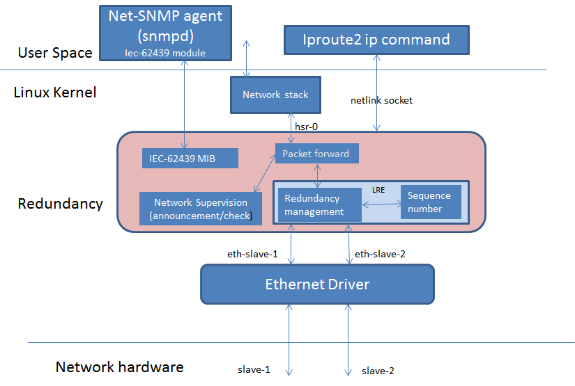
4.2.3.3. Software Architecture
The diagram below highlights the software components that are modified or developed specifically for HSR/PRP. These along with other standard Linux OS components are used to implement the Linux HSR/PRP DAN (Dual Attached Node).
- Linux Kernel drivers
- HSR/PRP driver
- Ethernet driver
- User space
- Net-SNMP
- iproute2
4.2.3.3.1. HSR/PRP Driver source code and Kconfig option
The driver source code is located under net/hsr-prp folder of the Linux source tree. To build kernel with this driver, set Kconfig option CONFIG_HSR_PRP=y in the dotconfig or enable it from the menu.
4.2.3.3.2. Linux HSR/PRP Driver
The Linux networking subsystem in upstream kernel has added support for HSR driver starting in v3.12 (HSRv0 - IEC 62439-3:2010) and enhanced the same to support HSRv1 (IEC 62439-3:2012) in v4.6. This driver allows user to create an HSR network device with a pair of slave network interfaces (A and B) that are standard Ethernet interfaces. For example on TI’s AM572x IDK EVM, there are two Ethernet interfaces (10/100) per each PRU ICSS. The PRU Emac driver available for ICSS PRU Ethernet h/w supports two Ethernet ports. Using ip link command, user will be able to setup a HSR interface on this EVM that pair the two PRU Ethernet interfaces to create a HSR node or DAN-H.
TI has enhanced the Linux HSR driver and ip link command in iproute2 package to support PRP defined in IEC 62439-3 clause 4. With this change, user will be able to create a Doubly Attached Node with PRP (DAN-P) using standard Ethernet interfaces. As in the case of HSR, using ip link command, user will be able to setup a prp interface using two Ethernet interfaces such as the one provided by PRU EMAC driver.
Linux HSR/PRP driver provides a standard Ethernet interface to application layer and hide the details of the redundancy protocol under the driver layer. Linux HSR/PRP driver implements the Link Redundancy Entity (LRE) that is central to implementing redundancy using respective protocol.
HSR LRE functions and L2 routing can be offloaded to the firmware running on the PRU cores of ICSS. The diagram below shows the architecture of an Offloaded HSR/PRP driver. The upper layer driver is existing Linux HSR/PRP driver described in the previous section. The PRU Ethernet driver exports HSR/PRP capabilities in the NetDev feature flags. The green blocks in the Redundancy layer shows the software blocks that gets offloaded to PRUs in ICSS which is shown green as well. The upper layer HSR/PRP driver uses the feature flags exported by the PRU Ethernet driver to disable corresponding functions in its layer. The firmware is a re-use from the TI RTOS implementation that is discussed above. Re-use means the data structures and API should be re-used across both TI RTOS and Linux driver implementations. A common PRU Ethernet driver is developed to support existing EMAC device as well HSR/PRP
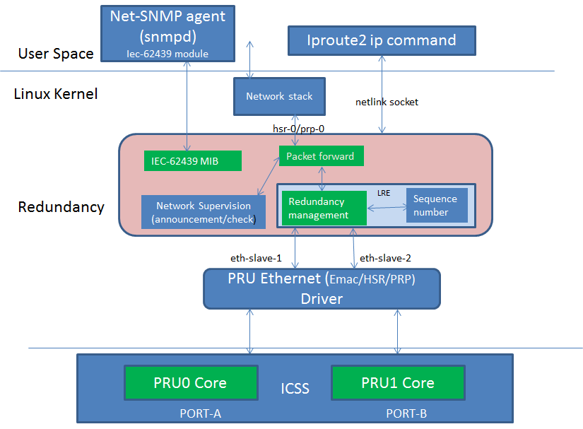
4.2.3.3.3. Ethernet Driver
Starting from Processor SDK 04.00.00 release, the PRU Ethernet driver supports HSR/PRP firmware offload. More specifically, based on a module parameter configured at boot time, the PRU Ethernet driver loads either a PRU EMAC firmware, PRU HSR firmware or PRU PRP firmware. The first case (EMAC) is the non-offload case, while the latter 2 cases are the firmware offload cases. When a HSR/PRP firmware is loaded, the PRU Ethernet driver will do proper firmware configurations and indicate offload capabilities in the netdev feature flag. The Linux HSR/PRP driver stack use these feature flag to determine if offload is supported or not at the lower level Ethernet driver and disable certain processing at the its layer.
Notice that, from the user point of view, other than providing a module parameter to specify which firmware to load, all of the above mentioned driver behavior is transparent to the user.
4.2.3.3.4. PRU Ethernet Driver (EMAC/HSR/PRP)
Starting from Processor SDK 04.00.00 release, the PRU Ethernet driver supports HSR/PRP firmware offload. More specifically, based on a module parameter configured at boot time, the PRU Ethernet driver loads either a PRU EMAC firmware, PRU HSR firmware or PRU PRP firmware. The first case (EMAC) is the non-offload case, while the latter 2 cases are the firmware offload cases. When a HSR/PRP firmware is loaded, the PRU Ethernet driver will do proper firmware configurations and notify the Linux HSR/PRP driver stack that offload has been enabled. From then on, LRE functionality is carried out in firmware.
Notice that, from the user point of view, other than providing a module parameter to specify which firmware to load, all of the above mentioned driver behavior is transparent to the user.
4.2.3.3.4.1. Queue Usage and VLAN PCP to Queue Map
At the Ingress, there are two queues assigned for packets coming from each port or PRU. Here is how the PCP values of incoming packets mapped to the each of the two queues. Firmware maintains a mapping table in the shared memory that is configured by the PRU Ethernet driver for HSR/PRP. For EMAC, the firmware has a similar mapping that is hard coded.
Ingress Host PCP to priority Queue map table in shared memory for HSR/PRP/EMAC
byte 0 => PRU 0 (eth2), PCP 0-3 => Q1
byte 1 => PRU 0 (eth2), PCP 4-7 => Q0
byte 2 => Unused.
byte 3 => Unused.
byte 4 => PRU 1 (eth3), PCP 0-3 => Q3
byte 5 => PRU 1 (eth3), PCP 4-7 => Q2
byte 6 => Unused
byte 7 => Unused
The convention is that higher queue value corresponds to lower priority
At the Ingress, two separate irq handlers are assigned to each port to process the packets. Driver handler first process packets from the high priority queue followed by packets from the lower priority queue.
At the Egress, there are 4 queues where driver enqueue the packets for Egress transmission. Following are the PCP to queue map used for Egress that are same across all protocols.
low  - pcp 0..1 maps to Q3
           2..3 maps to Q2
           4..5 maps to Q1
high - pcp 6..7 maps to Q0.
Firmware sends the frames first from Q1, and then from the next higher queue (Q2) and so forth.
4.2.3.3.4.2. Changing protocol at PRU Ethernet
PRU Ethernet driver support multiple protocols based on the firmware loaded on ICSS PRU. In Processor SDK 04.00.00, a capability was added to change the protocol running on the PRU at boot time through bootargs. This is described at Testing HSR/PRP Firmware Offload. Starting Processor SDK 04.01.00, The driver can be configured to switch the protocol while the board is powered up and running Linux kernel. By default, the PRU Ethernet driver is probed to be in the EMAC mode and EMAC firmware is loaded on to the PRU unless user set the pruss2_ethtype to run HSR (1) or PRP (2). Two feature names are added to help offload HSR or PRP in the PRU Ethernet driver :- hsr-rx-offload and prp-rx-offload. PRU Firmware essentially offload the rx side processing of LRE, such as duplicate detection and drop, node table update, stats update etc. To reflect the same, the features are named with a rx-offload suffx to the protocol name. Ethtool command has an option -K to set or clear the feature in a network device. So this flag can be set or reset rx offload feature in the PRU Ethernet device. As the device may be hooked up to a upper HSR/PRP network device, user is expected to delete the hsr or prp interface before changing the flag at the PRU Ethernet device. General procedure to change protocol at PRU Ethernet device is as follows:-
Below assumes that hsr or prp interface using the PRU Ethernet devices is currently deleted. Here are the steps at a high level:-
1. Bring down the two PRU Ethernet interfaces using ifconfig and unassign the ip address using ifconfig. For example
ifconfig eth2 down 0.0.0.0
ifconfig eth3 down 0.0.0.0
2. If the PRU Ethernet device is currently running HSR or PRP offload feature, the same has to be disabled before switching to EMAC or another protocol using ethtool -K option. For example if HSR is currently running, do
ethtool -K eth2 hsr-rx-offload off
ethtool -K eth3 hsr-rx-offload off
Similarly if PRP is currently running, do
ethtool -K eth2 prp-rx-offload off
ethtool -K eth3 prp-rx-offload off
3. If user would like to offload HSR, enable the feature hsr-rx-offload on both devices.
ethtool -K eth2 hsr-rx-offload on
ethtool -K eth3 hsr-rx-offload on
4. Now the PRU Ethernet devices can be paired to create an HSR interface using ip link command. To offload PRP user does following command in step 3
ethtool -K eth2 prp-rx-offload on
ethtool -K eth3 prp-rx-offload on
To display the offload feature currently active at the PRU Ethernet, user may type following command for example for eth2
ethtool -k eth2
Sample commands
Before using these commands, save the MAC address of both interfaces. These sample commands assumes a MAC address of 70:FF:76:1C:0E:8C for both PRU Ethernet interfaces and an IP address of 192.168.2.20 for the hsr/prp interface. Eth3 MAC address is assumed to be 70:FF:76:1C:0E:8E. Also assumes user create hsr0 or prp0 interface using eth2 and eth3 interfaces. Please note that for each DAN, user needs to assign unique MAC address and IP address from the same subnet.
- To switch from EMAC to HSR
ifconfig eth2 0.0.0.0 down
ifconfig eth3 0.0.0.0 down
ifconfig eth2 hw ether 70:FF:76:1C:0E:8C
ifconfig eth3 hw ether 70:FF:76:1C:0E:8C
ethtool -K eth2 hsr-rx-offload on
ethtool -K eth3 hsr-rx-offload on
ifconfig eth2 up
ifconfig eth3 up
ip link add name hsr0 type hsr slave1 eth2 slave2 eth3 supervision 45 version 1
ifconfig hsr0 192.168.2.20
- To switch from HSR to PRP
ip link delete hsr0
ifconfig eth2 down
ifconfig eth3 down
ethtool -K eth2 hsr-rx-offload off
ethtool -K eth3 hsr-rx-offload off
ethtool -K eth2 prp-rx-offload on
ethtool -K eth3 prp-rx-offload on
ifconfig eth2 up
ifconfig eth3 up
ip link add name prp0 type prp slave1 eth2 slave2 eth3 supervision 45
ifconfig prp0 192.168.2.20
- To switch from PRP to HSR
ip link delete prp0
ifconfig eth2 down
ifconfig eth3 down
ethtool -K eth2 prp-rx-offload off
ethtool -K eth3 prp-rx-offload off
ethtool -K eth2 hsr-rx-offload on
ethtool -K eth3 hsr-rx-offload on
ifconfig eth2 up
ifconfig eth3 up
ip link add name hsr0 type hsr slave1 eth2 slave2 eth3 supervision 45 version 1
ifconfig hsr0 192.168.2.20
- To switch from HSR to EMAC
ip link delete hsr0
ifconfig eth2 down
ifconfig eth3 down
#Restore eth3 MAC address
ifconfig eth3 hw ether 70:FF:76:1C:0E:8E
ethtool -K eth2 hsr-rx-offload off
ethtool -K eth3 hsr-rx-offload off
ifconfig eth2 192.168.2.20
ifconfig eth3 192.168.3.20
- To switch from PRP to EMAC
ip link delete prp0
ifconfig eth2 down
ifconfig eth3 down
ethtool -K eth2 prp-rx-offload off
ethtool -K eth3 prp-rx-offload off
#Restore eth3 MAC address
ifconfig eth3 hw ether 70:FF:76:1C:0E:8E
ifconfig eth2 192.168.2.20
ifconfig eth3 192.168.3.20
4.2.3.3.4.3. PRP EMAC mode
PRP EMAC mode is a special mode of PRP Ethernet type where the driver configures the PRP firmware to work like EMAC firmware. This is because currently PTP support is available only in PRU PRP firmware. So the current implementation of SAN with PTP requires PRUETH driver to be configured as PRP using bootargs. User needs to configure the PRP Firmware in PRP EMAC mode before bringing up the Ethernet interfaces. It is expected to add the PTP support to EMAC firmware in a future release. Until then this intermediate solution is used. Here are the steps to use PRUETH as SAN with PTP
- Boot the IDK EVM with prussX_ethtype in bootargs set to PRP as described at Testing HSR/PRP Firmware Offload
- Once the EVM boots up and user login, first thing to verify is if PRUETH is configured as PRP Ethernet type. See above section for details
- Configure PRP EMAC mode in the PRP firmware by issuing the following command at the console
echo 1 > /sys/kernel/debug/prueth-ethX/prp_emac_mode
where X is 2 or 3 or 4 or 5
- Now bring up Ethernet interfaces as usual and the device is ready to be used as SAN. PTP support can be enabled at this time. See section on [[1]] for the details.
NOTE: run time protocol switch is not supported for switch to SAN PTP for now and required boot time configuration and above debugfs command once device is boot up in PRP mode
4.2.3.4. Multicast filtering
Multicast filtering is an Ethernet frame filtering feature in PRU firmware based on the destination MAC address of the received frame. The PRU provides a Multicast filter table in Data RAM1 of PRU with a size of 256 entries of 1 byte each. Firmware implements an imperfect match for filtering the frames based on a hash calculated using the destination MAC address of the frame and a configurable mask if the destination address is a multicast MAC address.
Hash = (MAC_ADDR[0] AND MASK[0]) XOR
       (MAC_ADDR[1] AND MASK[1]) XOR
       (MAC_ADDR[2] AND MASK[2]) XOR
       (MAC_ADDR[3] AND MASK[3]) XOR
       (MAC_ADDR[4] AND MASK[4]) XOR
       (MAC_ADDR[5] AND MASK[5])
Where MASK is a user configurable value provided at boot time and MAC_ADDR is the multicast MAC address which is extracted from the destination address of the Ethernet frame and AND is the bitwise AND operation. In other words, a bitwise AND operation is performed between each byte of MAC address and a corresponding MASK byte and the resulting bytes are XOR-ed together to get the hash value. The hash is used to index into the Multicast filter table to check if it is set (1) or reset (0). If set, the frame is forwarded to ARM core (a.k.a Host). If reset, the frame is dropped at the PRU. This is an imperfect match since there can be multiple MAC addresses that produces the same hash value. So these frames will get forwarded to the ARM core.
ti_prueth.prussX_mc_mask is the module parameter for MASK where X is 1 for ICSS-1 and 2 for ICSS-2 on AM57xx (On other devices, X is 0 for ICSS-1 and 1 for ICSS-2).
Sample bootargs with MASK configured
setenv pruss1_mc_mask "FF:FF:FF:FF:00:00"
setenv pruss2_mc_mask "FF:FF:FF:FF:00:00"
setenv args_mmc 'run finduuid;setenv bootargs console=${console} ${optargs} root=PARTUUID=${uuid} rw rootfstype=${mmcrootfstype}  ti_prueth.pruss1_ethtype=${pruss1_ethtype} ti_prueth.pruss2_ethtype=${pruss2_ethtype} ti_prueth.pruss1_mc_mask=${pruss1_mc_mask} ti_prueth.pruss2_mc_mask=${pruss2_mc_mask}'
Typically, an application joins the multicast group either using a raw socket of type SOCK_DGRAM and use setsockopt() API to Join or leave the multicast group. An interesting article on this is available at
https://www.tenouk.com/Module41c.html
This causes the Multicast MAC address to be added to the mc_list of the socket and the associated network device in kernel and finally get passed to the Ethernet device driver (in our case, it is PRU Ethernet device driver). The relevant API is ndo_set_rx_mode() of the net_device_ops structure in Linux kernel associated with the network device. The PRU Ethernet device driver calculates the hash as described above and then writes 1 to MC filter table using the hash value as index. The PRU Ethernet device driver also supports allmulti which is used to enable receieve of all multicast frames at an interface. This is an option passed to the ifconfig command.
Example
>ifconfig eth2 192.168.2.20 allmulti

To remove the option
>ifconfig eth2 192.168.2.20 -allmulti

To display the Multicast address list of an interface, say eth2, user types
>ip maddr show dev eth2
sample display
root@am57xx-evm:~# ip maddr show dev eth2
6:      eth2
        link  33:33:00:00:00:01 users 2
        link  01:00:5e:00:00:01 users 2
        link  33:33:ff:1c:16:e0 users 2
        link  01:00:5e:00:00:fb
        link  01:00:5e:00:00:fc
        link  33:33:00:01:00:03 users 2
        link  33:33:00:00:00:fb users 2
        inet  224.0.0.1
        inet6 ff02::fb
        inet6 ff02::1:3
        inet6 ff02::1:ff1c:16e0
        inet6 ff02::1
        inet6 ff01::1
PRU Ethernet driver also provides a debugfs file mc_filter to display MC filter table in the memory
/sys/kernel/debug/prueth-prp/mc_filter
or
/sys/kernel/debug/prueth-hsr/mc_filter
Sample display
root@am57xx-evm:~# cat /sys/kernel/debug/prueth-prp/mc_filter
MC Filter : enabled
MC Mask : ff:ff:ff:ff:0:0
MC Filter table below 1 - Allowed, 0 - Dropped

  0: 1 1 0 0 0 0 0 0 0 0 0 0 0 0 0 0
 10: 0 0 0 0 0 0 0 0 0 0 0 0 0 0 0 0
 20: 0 0 0 0 0 0 0 0 0 0 0 0 0 0 0 0
 30: 0 0 0 0 0 0 0 0 0 0 0 0 0 0 0 0
 40: 0 0 0 0 0 0 0 0 0 0 0 0 0 0 0 0
 50: 0 0 0 0 0 0 0 0 0 0 0 0 0 0 0 1
 60: 0 0 0 0 0 0 0 0 0 0 0 0 0 0 0 0
 70: 0 0 0 0 0 0 0 0 0 0 0 0 0 0 0 0
 80: 0 0 0 0 0 0 0 0 0 0 0 0 0 0 0 0
 90: 0 0 0 0 0 0 0 0 0 0 0 0 0 0 0 0
 a0: 0 0 0 0 0 0 0 0 0 0 0 0 0 0 0 0
 b0: 0 0 0 0 0 0 0 0 0 0 0 0 0 0 0 0
 c0: 0 0 0 0 0 0 0 0 0 0 0 0 0 0 0 0
 d0: 0 0 0 0 0 0 0 0 0 0 0 0 0 0 0 0
 e0: 0 0 0 1 0 0 0 0 0 0 0 0 0 0 0 0
 f0: 0 0 0 0 0 0 0 0 0 0 0 0 0 0 0 0
4.2.3.5. VLAN over PRU Ethernet
Virtual LAN (VLAN) is a standard Linux feature that can be enabled over PRU Ethernet devices. There are many websites that describes how Linux VLAN works. Some of them are at [[2]] or at [[3]] and some configuration details are also discussed at [[4]].
User may use ip link command to setup vlan interface over prueth interfaces. For example, over a hsr interface, if user would like to setup two vlan interfaces say, hsr0.2 and hsr0.3, user execute the following commands assuming the hsr0 interface is already setup:-
Node-1
ifconfig hsr0 0.0.0.0
ip link add link hsr0 name hsr0.2 type vlan id 2
ip link add link hsr0 name hsr0.3 type vlan id 3
ifconfig hsr0.2 192.168.2.40
ifconfig hsr0.3 192.168.3.40
ip link set hsr0.2 type vlan egress 0:0
ip link set hsr0.3 type vlan egress 0:7
Node-2
ifconfig hsr0 0.0.0.0
ip link add link hsr0 name hsr0.2 type vlan id 2
ip link add link hsr0 name hsr0.3 type vlan id 3
ifconfig hsr0.2 192.168.2.50
ifconfig hsr0.3 192.168.3.50
ip link set hsr0.2 type vlan egress 0:0
ip link set hsr0.3 type vlan egress 0:7
The above assume we have a network with two nodes connected back to back. The procedure is same if more than two nodes are present in the network. Using similar commands, user would be able to overlay multiple virtual LANs over the physical LAN created. The egress option of ip link command allow mapping packet priority to VLAN PCP values. In the example the packets on VLAN ID 2 is mapped to PCP value of 0 and VLAN ID 3 is mapped to PCP value of 7. At the Egress PRU Ethernet device looks at the PCP value and places it into one of the 4 queues. PRU scan the high priority queue first for packets and transmits them before transmitting packets from the lower priority queues. At the ingress, the PRU checks the PCP value of the packet in the VLAN header and places the frame into one of the ingress queues. More details on Queue usage is available at Queue Usage and VLAN PCP to Queue Map
In the above example, after passing some UDP traffic over hsr0.2 and hsr0.3, the user may check following statistics to verify if the packets are going over the right VLAN interface
On Node-1
cat /proc/net/vlan/hsr0.3
hsr0.3  VID: 3   REORDER_HDR: 1  dev->priv_flags: 1001
         total frames received        68090
          total bytes received     52598480
      Broadcast/Multicast Rcvd           52
      total frames transmitted        68090
       total bytes transmitted     52598459
Device: hsr0
INGRESS priority mappings: 0:0  1:0  2:0  3:0  4:0  5:0  6:0 7:0
 EGRESS priority mappings: 0:7
root@am57xx-evm:~# cat /proc/net/vlan/hsr0.2
hsr0.2  VID: 2   REORDER_HDR: 1  dev->priv_flags: 1001
        total frames received        68105
         total bytes received     52604702
      Broadcast/Multicast Rcvd           53

      total frames transmitted        68074
       total bytes transmitted     52583138
Device: hsr0
INGRESS priority mappings: 0:0  1:0  2:0  3:0  4:0  5:0  6:0 7:0
 EGRESS priority mappings: 0:0
root@am57xx-evm:~# cat /sys/kernel/debug/prueth-eth2/stats
   TxQ-0    TxQ-1    TxQ-2    TxQ-3    RxQ-0    RxQ-1
=====================================================
   68041        0        0    68908    67809    68925
root@am57xx-evm:~# cat /sys/kernel/debug/prueth-eth3/stats
   TxQ-0    TxQ-1    TxQ-2    TxQ-3    RxQ-2    RxQ-3
=====================================================
   68041        0        0    68912      234      695
Similar procedure can be used for setting up VLAN interfaces over PRU EMAC and HSR Ethernet types.
4.2.3.6. VLAN Filtering
The PRU has a 4096 entry VLAN filter table that allows filtering out unwanted VLAN traffic to the host. As soon a VLAN interface is created, the 802.1q Linux kernel module sends the VID information down to the lower layer HSR or PRP Linux device which in turn pass it down to the slave Ethernet devices below it. The PRU Ethernet driver gets the VID information via net_device_ops:ndo_vlan_rx_add_vid(). On receiving this, PRU Etherent driver sets the entry at the VID index in VLAN filter table to 1. When the VLAN interface is deleted, the driver receives the same information through ndo_vlan_rx_kill_vid() and reset the entry at the VID index.
PRU firmware on receiving a VLAN frame, extracts the VID and look up the VLAN filter table for an entry at the VID if VLAN filtering is enabled in firmware. If the entry is 1, it forwards the frame to the Host. Otherwise the frame is dropped. There are additional controls to allow priority tagged frames to Host if the corrsponding bit is set in firmware shared memory. PRU Ethernet driver always enables Priority tagged frames to the Host. User may setup a VLAN interface with VID 0 to send or receive priority tagged frames. See section VLAN for details on how to assign egress priority mapping for the priority tagged VLAN interface.
Useful commands
User can use the following command to view the VLAN filter table at PRU.
root@am57xx-evm:~# cat /sys/kernel/debug/prueth-prp/vlan_filter
VLAN Filter : enabled

   0: 0011000000000000000000000000000000000000000000000000000000000000
  64: 0000000000000000000000000000000000000000000000000000000000000000
 128: 0000000000000000000000000000000000000000000000000000000000000000
 192: 0000000000000000000000000000000000000000000000000000000000000000
 256: 0000000000000000000000000000000000000000000000000000000000000000
 320: 0000000000000000000000000000000000000000000000000000000000000000
 384: 0000000000000000000000000000000000000000000000000000000000000000
 448: 0000000000000000000000000000000000000000000000000000000000000000
 512: 0000000000000000000000000000000000000000000000000000000000000000
 576: 0000000000000000000000000000000000000000000000000000000000000000
 640: 0000000000000000000000000000000000000000000000000000000000000000
 704: 0000000000000000000000000000000000000000000000000000000000000000
 768: 0000000000000000000000000000000000000000000000000000000000000000
 832: 0000000000000000000000000000000000000000000000000000000000000000
 896: 0000000000000000000000000000000000000000000000000000000000000000
 960: 0000000000000000000000000000000000000000000000000000000000000000
1024: 0000000000000000000000000000000000000000000000000000000000000000
1088: 0000000000000000000000000000000000000000000000000000000000000000
1152: 0000000000000000000000000000000000000000000000000000000000000000
1216: 0000000000000000000000000000000000000000000000000000000000000000
1280: 0000000000000000000000000000000000000000000000000000000000000000
1344: 0000000000000000000000000000000000000000000000000000000000000000
1408: 0000000000000000000000000000000000000000000000000000000000000000
1472: 0000000000000000000000000000000000000000000000000000000000000000
1536: 0000000000000000000000000000000000000000000000000000000000000000
1600: 0000000000000000000000000000000000000000000000000000000000000000
1664: 0000000000000000000000000000000000000000000000000000000000000000
1728: 0000000000000000000000000000000000000000000000000000000000000000
1792: 0000000000000000000000000000000000000000000000000000000000000000
1856: 0000000000000000000000000000000000000000000000000000000000000000
1920: 0000000000000000000000000000000000000000000000000000000000000000
1984: 0000000000000000000000000000000000000000000000000000000000000000
2048: 0000000000000000000000000000000000000000000000000000000000000000
2112: 0000000000000000000000000000000000000000000000000000000000000000
2176: 0000000000000000000000000000000000000000000000000000000000000000
2240: 0000000000000000000000000000000000000000000000000000000000000000
2304: 0000000000000000000000000000000000000000000000000000000000000000
2368: 0000000000000000000000000000000000000000000000000000000000000000
2432: 0000000000000000000000000000000000000000000000000000000000000000
2496: 0000000000000000000000000000000000000000000000000000000000000000
2560: 0000000000000000000000000000000000000000000000000000000000000000
2624: 0000000000000000000000000000000000000000000000000000000000000000
2688: 0000000000000000000000000000000000000000000000000000000000000000
2752: 0000000000000000000000000000000000000000000000000000000000000000
2816: 0000000000000000000000000000000000000000000000000000000000000000
2880: 0000000000000000000000000000000000000000000000000000000000000000
2944: 0000000000000000000000000000000000000000000000000000000000000000
3008: 0000000000000000000000000000000000000000000000000000000000000000
3072: 0000000000000000000000000000000000000000000000000000000000000000
3136: 0000000000000000000000000000000000000000000000000000000000000000
3200: 0000000000000000000000000000000000000000000000000000000000000000
3264: 0000000000000000000000000000000000000000000000000000000000000000
3328: 0000000000000000000000000000000000000000000000000000000000000000
3392: 0000000000000000000000000000000000000000000000000000000000000000
3456: 0000000000000000000000000000000000000000000000000000000000000000
3520: 0000000000000000000000000000000000000000000000000000000000000000
3584: 0000000000000000000000000000000000000000000000000000000000000000
3648: 0000000000000000000000000000000000000000000000000000000000000000
3712: 0000000000000000000000000000000000000000000000000000000000000000
3776: 0000000000000000000000000000000000000000000000000000000000000000
3840: 0000000000000000000000000000000000000000000000000000000000000000
3904: 0000000000000000000000000000000000000000000000000000000000000000
3968: 0000000000000000000000000000000000000000000000000000000000000000
4032: 0000000000000000000000000000000000000000000000000000000000000000
Limitations
Currently, the PRU firmware is configured to receive all of the untagged frames from the network when the VLAN filtering is enabled. However there is no support for port VLAN which allows these frames to be received at a designated VLAN interface.
4.2.3.7. Net-SNMP
The TI SDK release ships tisdk-rootfs-image-am57xx-evm.tar.xz with Net-SNMP 5.7.3 binaries pre-installed and snmpd is started as part of the user space initialization. TI has developed a Net-SNMP module to support IEC-62439-3 related MIB access at the DAN using snmp commands such as snmpwalk, snmpget etc. NOTE: IEC-62439-3 MIB is supported only in the offloaded case. So user is expected to create HSR/PRP interface with offload. For details on how to setup HSR/PRP interface with offload, please refer Testing HSR/PRP Firmware Offload
Command examples
An example snmpwalk command execution is shown below where 192.168.2.20 is the IP address of the remote DAN-P or DAN-H prp/hsr interface.
root@am57xx-evm:/etc/snmp# snmpwalk -v 2c -c public 192.168.2.20 iec62439
IEC-62439-3-MIB::lreManufacturerName.0 = STRING: TI LRE
IEC-62439-3-MIB::lreInterfaceCount.0 = INTEGER: 1
IEC-62439-3-MIB::lreRowStatus.1 = INTEGER: active(1)
IEC-62439-3-MIB::lreNodeType.1 = INTEGER: hsr(2)
IEC-62439-3-MIB::lreNodeName.1 = STRING: hsr0
IEC-62439-3-MIB::lreVersionName.1 = ""
IEC-62439-3-MIB::lreMacAddress.1 = STRING: d2:ef:e6:2a:1f:5b
IEC-62439-3-MIB::lrePortAdminStateA.1 = INTEGER: active(2)
IEC-62439-3-MIB::lrePortAdminStateB.1 = INTEGER: active(2)
IEC-62439-3-MIB::lreLinkStatusA.1 = INTEGER: up(1)
IEC-62439-3-MIB::lreLinkStatusB.1 = INTEGER: up(1)
IEC-62439-3-MIB::lreDuplicateDiscard.1 = INTEGER: discard(2)
IEC-62439-3-MIB::lreTransparentReception.1 = INTEGER: 0
IEC-62439-3-MIB::lreHsrLREMode.1 = INTEGER: modeh(1)
IEC-62439-3-MIB::lreSwitchingEndNode.1 = INTEGER: hsrnode(5)
IEC-62439-3-MIB::lreRedBoxIdentity.1 = INTEGER: id1a(2)
IEC-62439-3-MIB::lreEvaluateSupervision.1 = INTEGER: true(1)
IEC-62439-3-MIB::lreNodesTableClear.1 = INTEGER: noOp(0)
IEC-62439-3-MIB::lreProxyNodeTableClear.1 = INTEGER: noOp(0)
IEC-62439-3-MIB::lreDupListResideMaxTime.1 = INTEGER: 26214 binaryFractionOfSecond
IEC-62439-3-MIB::lreCntTxA.1 = Counter32: 7384
IEC-62439-3-MIB::lreCntTxB.1 = Counter32: 7385
IEC-62439-3-MIB::lreCntTxC.1 = Counter32: 4032
IEC-62439-3-MIB::lreCntErrWrongLanA.1 = Counter32: 0
IEC-62439-3-MIB::lreCntErrWrongLanB.1 = Counter32: 0
IEC-62439-3-MIB::lreCntErrWrongLanC.1 = Counter32: 0
IEC-62439-3-MIB::lreCntRxA.1 = Counter32: 4024
IEC-62439-3-MIB::lreCntRxB.1 = Counter32: 4025
IEC-62439-3-MIB::lreCntRxC.1 = Counter32: 0
IEC-62439-3-MIB::lreCntErrorsA.1 = Counter32: 3351
IEC-62439-3-MIB::lreCntErrorsB.1 = Counter32: 3351
IEC-62439-3-MIB::lreCntErrorsC.1 = Counter32: 0
IEC-62439-3-MIB::lreCntNodes.1 = INTEGER: 1
IEC-62439-3-MIB::lreCntProxyNodes.1 = INTEGER: 0
IEC-62439-3-MIB::lreCntUniqueA.1 = Counter32: 4
IEC-62439-3-MIB::lreCntUniqueB.1 = Counter32: 4
IEC-62439-3-MIB::lreCntUniqueC.1 = Counter32: 0
IEC-62439-3-MIB::lreCntDuplicateA.1 = Counter32: 0
IEC-62439-3-MIB::lreCntDuplicateB.1 = Counter32: 0
IEC-62439-3-MIB::lreCntDuplicateC.1 = Counter32: 3992
IEC-62439-3-MIB::lreCntMultiA.1 = Counter32: 0
IEC-62439-3-MIB::lreCntMultiB.1 = Counter32: 0
IEC-62439-3-MIB::lreCntMultiC.1 = Counter32: 0
IEC-62439-3-MIB::lreCntOwnRxA.1 = Counter32: 0
IEC-62439-3-MIB::lreCntOwnRxB.1 = Counter32: 0
IEC-62439-3-MIB::lreNodesMacAddress.1.1 = STRING: 70:ff:76:1c:f:8d
IEC-62439-3-MIB::lreTimeLastSeenA.1.1 = Timeticks: (0) 0:00:00.00
IEC-62439-3-MIB::lreTimeLastSeenB.1.1 = Timeticks: (1) 0:00:00.01
IEC-62439-3-MIB::lreRemNodeType.1.1 = INTEGER: danh(3)
Individual MIB variable may be queried or set using snmpset or snmpget commands. Below are some examples:- snmpset
snmpset -v 2c -c private 192.168.2.20 IEC-62439-3-MIB::lreHsrLREMode.1 i 3
snmpget
snmpget -v 2c -c public 192.168.2.20 IEC-62439-3-MIB::lreManufacturerName.0
MIB Support
| MIB variable | Group | Actions Specified by Standard | Action supported |
|---|---|---|---|
| lreManufacturerName | lreConfigurationGeneralGroup | get | get |
| lreInterfaceCount | lreConfigurationGeneralGroup | get | get |
| lreInterfaceConfigTable | lreConfigurationInterfaceGroup | NA | NA |
| lreInterfaceConfigEntry | lreConfigurationInterfaceGroup | NA | NA |
| lreInterfaceConfigIndex | lreConfigurationInterfaceGroup | NA | NA |
| lreRowStatus | lreConfigurationInterfaceGroup | NA | get |
| lreNodeType | lreConfigurationInterfaceGroup | get/set | get |
| lreNodeName | lreConfigurationInterfaceGroup | get/set | get |
| lreVersionName | lreConfigurationInterfaceGroup | get | get |
| lreMacAddress | lreConfigurationInterfaceGroup | get/set | get |
| lrePortAdminStateA | lreConfigurationInterfaceGroup | get/set | get |
| lrePortAdminStateB | lreConfigurationInterfaceGroup | get/set | get |
| lreLinkStatusA | lreConfigurationInterfaceGroup | get | get |
| lreLinkStatusB | lreConfigurationInterfaceGroup | get | get |
| lreDuplicateDiscard | lreConfigurationInterfaceGroup | get/set | get/set |
| lreTransparentReception | lreConfigurationInterfaceGroup | get/set | get/set |
| lreHsrLREMode | lreConfigurationInterfaceGroup | get/set | get/set |
| lreSwitchingEndNode | lreConfigurationInterfaceGroup | get/set | get |
| lreRedBoxIdentity | lreConfigurationInterfaceGroup | get/set | NS |
| lreEvaluateSupervision | lreConfigurationInterfaceGroup | get/set | NS |
| lreNodesTableClear | lreConfigurationInterfaceGroup | get/set | get/set |
| lreProxyNodeTableClear | lreConfigurationInterfaceGroup | get/set | NS |
| lreDupListResideMaxTime | lreConfigurationInterfaceGroup | get/set | get |
| lreInterfaceStatsTable | lreStatisticsInterfaceGroup | NA | NA |
| lreInterfaceStatsEntry | lreStatisticsInterfaceGroup | NA | NA |
| lreInterfaceStatsIndex | lreStatisticsInterfaceGroup | NA | Yes |
| lreCntTxA | lreStatisticsInterfaceGroup | get | get |
| lreCntTxB | lreStatisticsInterfaceGroup | get | get |
| lreCntTxC | lreStatisticsInterfaceGroup | get | get |
| lreCntErrWrongLanA | lreStatisticsInterfaceGroup | get | get |
| lreCntErrWrongLanB | lreStatisticsInterfaceGroup | get | get |
| lreCntErrWrongLanC | lreStatisticsInterfaceGroup | get | get |
| lreCntRxA | lreStatisticsInterfaceGroup | get | get |
| lreCntRxB | lreStatisticsInterfaceGroup | get | get |
| lreCntRxC | lreStatisticsInterfaceGroup | get | get |
| lreCntErrorsA | lreStatisticsInterfaceGroup | get | get |
| lreCntErrorsB | lreStatisticsInterfaceGroup | get | get |
| lreCntErrorsC | lreStatisticsInterfaceGroup | get | get |
| lreCntNodes | lreStatisticsInterfaceGroup | get | get |
| lreCntProxyNodes | lreStatisticsInterfaceGroup | get | NS |
| lreCntUniqueA | lreStatisticsInterfaceGroup | get | get |
| lreCntUniqueB | lreStatisticsInterfaceGroup | get | get |
| lreCntUniqueC | lreStatisticsInterfaceGroup | get | get |
| lreCntDuplicateA | lreStatisticsInterfaceGroup | get | get |
| lreCntDuplicateB | lreStatisticsInterfaceGroup | get | get |
| lreCntDuplicateC | lreStatisticsInterfaceGroup | get | get |
| lreCntMultiA | lreStatisticsInterfaceGroup | get | get |
| lreCntMultiB | lreStatisticsInterfaceGroup | get | get |
| lreCntMultiC | lreStatisticsInterfaceGroup | get | get |
| lreCntOwnRxA | lreStatisticsInterfaceGroup | get | get |
| lreCntOwnRxB | lreStatisticsInterfaceGroup | get | get |
| lreNodesTable | lreStatisticsInterfaceGroup | NA | Yes |
| lreNodesIndex | lreStatisticsInterfaceGroup | NA | Yes |
| lreNodesMacAddress | lreStatisticsInterfaceGroup | get | get |
| lreTimeLastSeenA | lreStatisticsInterfaceGroup | get | get |
| lreTimeLastSeenB | lreStatisticsInterfaceGroup | get | get |
| lreRemNodeType | lreStatisticsInterfaceGroup | get | get |
| lreProxyNodeTable | lreStatisticsInterfaceGroup | NS | |
| lreProxyNodeEntry | lreStatisticsInterfacesGroup | NA | NS |
| lreProxyNodeMacAddress | lreStatisticsInterfacesGroup | get | NS |
Note NS: Not supported, NA: Not Applicable
4.2.3.8. iproute2
iproute2 is enhanced to allow creating a prp interface similar to hsr interface using two slave interfaces.
4.2.3.9. Test Procedure
4.2.3.9.1. Testing HSR/PRP Firmware Offload
The setup of the IDKs for testing HSR/PRP firmware offload and the configuration of the HSR/PRP interfaces after kernel boot up are no different than the case without firmware offload. The differences are, in the case of firmware offload, the correct PRU firmware needs to be loaded and the PRUETH driver needs to be configured to interface with the type of firmware loaded, during boot up.
The module parameter “ti_prueth.pruss1_ethtype” and “ti_prueth.pruss2_ethtype” are used for instructing the PRU Ethernet driver what type of PRU firmware is to be loaded to PRU-ICSS1 and PRU-ICSS2 respectively. These type values are:
| ti_prueth.prussX_ethtype, X = 1,2 | firmware type |
|---|---|
| 0 | EMAC |
| 1 | HSR |
| 2 | PRP |
These ti_prueth.prussX_type values can be set up in the Kernel boot argument in Uboot. For example, to load HSR firmware to PRU-ICSS1 and PRP firmware to PRU-ICSS2, and assuming boot using NFS rootfs, the Kernel boot argument can be configured as follows. Under Uboot prompt,
 => setenv netargs 'setenv bootargs console=${console} ${optargs} root=/dev/nfs nfsroot=${serverip}:${rootpath},${nfsopts} rw ip=dhcp
ti_prueth.pruss1_ethtype=${pruss1_ethtype} ti_prueth.pruss2_ethtype=${pruss2_ethtype}'
 => setenv pruss1_ethtype 1
 => setenv pruss2_ethtype 2
 => saveenv
NOTE If using mmc rootfs, update args_mmc as below
 => setenv args_mmc 'run finduuid;setenv bootargs console=${console} ${optargs} root=PARTUUID=${uuid} rw rootfstype=${mmcrootfstype}
ti_prueth.pruss1_ethtype=${pruss1_ethtype} ti_prueth.pruss2_ethtype=${pruss2_ethtype}'
Just change the value of pruss1_ethtype or pruss2_ethtype in the above example to switch to a different type of firmware (see the above table). If a ti_prueth.prussX_ethtype is not configured, ie. does not appear in Kernel boot argument, the default EMAC firmware will be loaded to the corresponding PRU-ICSSX. In this case, if user sets up HSR/PRP interface, it will work without offload using the PRU EMAC firmware and driver. So using offload or no offload is controlled via selecting appropriate firmware at boot up and is transparent to user.
Remarks:
- Setting ti_prueth.prussX_ethtype to 0 is the same as not using it in the Kernel argument. In either case, default EMAC firmware is loaded.
- “ti_prueth.prussX_ethtype=”, ie. setting the module parameter but without a value, is incorrect.
- On AM572x IDK, only PRU-ICSS2 is supported. Hence only prueth.pruss2_type takes effect.
To verify PRU Ethernet type after boot, do following that display TI PRU ethernet type
dmesg | grep "TI PRU ethernet (type"
For PRU Emac, the string displayed will be
prueth pruss2_eth: TI PRU ethernet (type 0) driver initialized
For PRU HSR, the string displayed will be
prueth pruss2_eth: TI PRU ethernet (type 1) driver initialized
For PRU PRP, the string displayed will be
prueth pruss2_eth: TI PRU ethernet (type 2) driver initialized
Where type is what is set in the bootargs and is listed in the table at the beginning of this section
4.2.3.9.2. Node Tables (firmware offload)
In the case of HSR/PRP firmware offload, the Node Table can be displayed as follows. Note: the locations are different from those when there is no firmware offload.
To show the HSR Node Table, under the kernel prompt on the terminal connected to the IDK, do
- root@am57xx-evm:~# cat /sys/kernel/debug/prueth-hsr/node_table
- Sample display
root@am57xx-evm:~# cat /sys/kernel/debug/prueth-hsr/node_table

Remote nodes in network: 1

Node[1]:
MAC ADDR: 70:ff:76:1c:0f:99
state: valid
DANH
RxA=2992 SupRxA=148
RxB=2992 SupRxB=148
Time Last Seen: Sup=0 RxA=0 RxB=0
To show the PRP Node Table, under the kernel prompt on the terminal connected to the IDK, do
- root@am57xx-evm:~# cat /sys/kernel/debug/prueth-prp/node_table
- Sample display
root@am57xx-evm:~# cat /sys/kernel/debug/prueth-prp/node_table

Remote nodes in network: 1

Node[1]:
MAC ADDR: 70:ff:76:1c:0f:99
state: valid
DupDiscard (0x80)
DANP
RxA=17 SupRxA=17
RxB=17 SupRxB=17
Time Last Seen: Sup=0 RxA=0 RxB=0
PRP LineID Err: A=0 B=0
4.2.3.9.3. LRE Statistics (firmware offload)
The LRE statistics is displayed as part the interface statistics using the “ethtool -S DEVNAME” command, where DEVNAME, in the case AM572x IDK, is eth2 or eth3. The fields pertaining to LRE statistics are prefixed with “lre”. Since LRE statistics are LRE specific, instead of interface specific, so either “ethtool -S eth2” or “ethtool -S eth3” will show the same LRE statistics.
Sample display:
root@am57xx-evm:~# ethtool -S eth2
NIC statistics:
     txBcast: 1
     txMcast: 11635
     txUcast: 3
     txOctets: 816642
     rxBcast: 0
     rxMcast: 36
     rxUcast: 17
     rxOctets: 4841
     tx64byte: 6
     tx65_127byte: 11633
     tx128_255byte: 0
     tx256_511byte: 0
     tx512_1023byte: 0
     tx1024byte: 0
     rx64byte: 4
     rx65_127byte: 49
     rx128_255byte: 0
     rx256_511byte: 0
     rx512_1023byte: 0
     rx1024byte: 0
     lateColl: 0
     singleColl: 0
     multiColl: 0
     excessColl: 0
     rxMisAlignmentFrames: 0
     stormPrevCounter: 0
     macRxError: 0
     SFDError: 0
     defTx: 0
     macTxError: 0
     rxOverSizedFrames: 0
     rxUnderSizedFrames: 0
     rxCRCFrames: 0
     droppedPackets: 0
     txHWQOverFlow: 0
     txHWQUnderFlow: 0
     lreTxA: 11636
     lreTxB: 11639
     lreTxC: 66
     lreErrWrongLanA: 0
     lreErrWrongLanB: 0
     lreErrWrongLanC: 0
     lreRxA: 40
     lreRxB: 40
     lreRxC: 0
     lreErrorsA: 11560
     lreErrorsB: 11559
     lreErrorsC: 0
     lreNodes: 0
     lreProxyNodes: 0
     lreUniqueRxA: 0
     lreUniqueRxB: 0
     lreUniqueRxC: 0
     lreDuplicateRxA: 0
     lreDuplicateRxB: 0
     lreDuplicateRxC: 0
     lreMultiRxA: 0
     lreMultiRxB: 0
     lreMultiRxC: 0
     lreOwnRxA: 0
     lreOwnRxB: 0
     lreDuplicateDiscard: 2
     lreTransRecept: 1
     lreNtLookupErrA: 0
     lreNtLookupErrB: 0
     lreNodeTableFull: 0
4.2.3.9.4. HSR Testing
To test HSR, user would need two AM572x EVMs.
- Setup HSR Ring network as per diagram below. Connect the PRU2ETH0 (See the marking on the EVM) Ethernet ports of the two EVMs together (corresponds to Linux interface eth2) as shown below. Similarly, connect the PRU2ETH1 ports (Linux interface eth3) as well.
- Configure the bootargs to boot PRU with HSR firmware as described above at Testing HSR/PRP Firmware Offload
- Boot the EVMs using the pre-built images from the Processor SDK release. These images are built with Linux HSR/PRP driver enabled. Login to the console using root user name.
- Note the MAC Address of eth2 at DAN-H-1(Say MAC-A) using the ifconfig command. Do ifconfig eth2 at the Linux console of DAN-H-1
- Note the MAC Address of eth2 at DAN-H-2(Say MAC-B) using the ifconfig
command. Do ifconfig eth2 at the Linux console of DAN-H-2
- ifconfig eth2 down
- ifconfig eth3 down
- ifconfig eth3 hw ether <MAC-A>
- ifconfig eth2 up
- ifconfig eth3 up
- ip link add name hsr0 type hsr slave1 eth2 slave2 eth3 supervision 45 version 1
- ifconfig hsr0 <IP Address of hsr interface at DAN-H-1> up
- Repeat the above steps for DAN-H-2, but this time use MAC-B in step 4.3 above. And use IP Address from the same subnet as that of DAN-H-1 hsr interface hsr0.
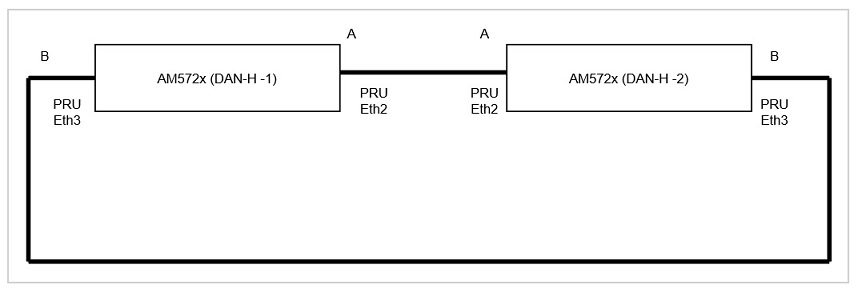
For example use Ip Address 192.168.2.20 for DAN-H-1 and 192.168.2.30 for DAN-H-2. Assume CPSW ports at the EVM are on a different Subnet than the HSR interface.
Once both hsr0 interfaces are created, user should be able to do a ping from DAN-H-1 to DAN-H-2 or vice-versa. Disconnect Ethernet cable at eth2 or eth3. The Ping should continue to go through. User could run iperf between the two HSR interfaces and test the iperf is not affected when one of the cable is disconnected. This verifies redundancy.
A Sample script that automates the steps 4.1 to 4.7, say setup.sh, is below
#!/bin/sh
if [ $# -lt 3 ]
then
        echo "setup.sh <hsr/prp> <MAC-Address for both slaves> <ip address for hsr/prp interface>"
        exit
fi

if [ "$1" != "hsr" ] && [ "$1" != "prp" ]
then
    echo "use hsr or prp as first argument"
    exit
fi

echo "Setting up $10 interface with MAC address $2 for slaves and IP address $3"

ifconfig eth2 down
ifconfig eth3 down
ifconfig eth2 hw ether $2
ifconfig eth3 hw ether $2
ifconfig eth2 up
ifconfig eth3 up

if [ "$1" == "hsr" ]
then
        ip link add name hsr0 type hsr slave1 eth2 slave2 eth3 supervision 45 version 1
        ifconfig hsr0 $3 up
else
        ip link add name prp0 type prp slave1 eth2 slave2 eth3 supervision 45
        ifconfig prp0 $3 up
fi
Using this script, user can setup hsr interface as
/setup.sh hsr <MAC-A> <IP Address of the interface>
where it is assumed that the setup.sh is copied to the root directory of the target file system and is made executable
Below script can be used to teardown the hsr interface (say teardown.sh)
#!/bin/sh
if [ $# -lt 1 ]
then
        echo "teardown.sh <hsr/prp>"
        exit
fi

if [ "$1" != "hsr" ] && [ "$1" != "prp" ]
then
    echo "use hsr or prp as first argument"
    exit
fi

if [ "$1" == "hsr" ]
then
        ip link del hsr0
else
        ip link del prp0
fi
Using the above script, user teardown the hsr interface as
/teardown.sh hsr
Sample logs are shown below:
DAN-H-1
root@am57xx-evm:~# ifconfig eth2
eth2      Link encap:Ethernet  HWaddr 70:FF:76:1C:0F:8D  [   38.944687] random: nonblocking pool is initialized
          BROADCAST MULTICAST  MTU:1500  Metric:1
          RX packets:0 errors:0 dropped:0 overruns:0 frame:0
          TX packets:0 errors:0 dropped:0 overruns:0 carrier:0
          collisions:0 txqueuelen:1000
           RX bytes:0 (0.0 B)  TX bytes:0 (0.0 B)

root@am57xx-evm:~# /setup.sh hsr 70:FF:76:1C:0F:8D 192.168.2.20
Setting up hsr0 interface with MAC address 70:FF:76:1C:0F:8D for slaves and IP address 192.168.2.20
[   62.319328]  remoteproc6: powering up 4b2b4000.pru0
[   62.325015]  remoteproc6: Booting fw image ti-pruss/am57xx-pru0-prueth-fw.elf, size 4350
[   62.335303] ti-pruss 4b280000.pruss: configured system_events = 0x0000060000500000 intr_channels = 0x00000095 host_intr = 0x00000115
[   62.348724]  remoteproc6: remote processor 4b2b4000.pru0 is now up
[   62.354947] net eth2: started
[   62.360842] IPv6: ADDRCONF(NETDEV_UP): eth2: link is not ready
[   62.408479]  remoteproc7: powering up 4b2b8000.pru1
[   62.413790]  remoteproc7: Booting fw image ti-pruss/am57xx-pru1-prueth-fw.elf, size 4382
[   62.422088] ti-pruss 4b280000.pruss: configured system_events = 0x0060000000a00000 intr_channels = 0x0000012a host_intr = 0x0000022a
[   62.434059]  remoteproc7: remote processor 4b2b8000.pru1 is now up
[   62.440281] net eth3: started
[   62.444625] IPv6: ADDRCONF(NETDEV_UP): eth3: link is not ready
[   62.509276] device eth2 entered promiscuous mode
[   62.549502] device eth3 entered promiscuous mode
[   62.593878] hsr0: Slave A (eth2) is not up; please bring it up to get a fully working HSR network
[   62.604214] IPv6: ADDRCONF(NETDEV_UP): hsr0: link is not ready
[   62.614722] IPv6: ADDRCONF(NETDEV_CHANGE): hsr0: link becomes ready
root@am57xx-evm:~#
root@am57xx-evm:~# [   63.648569] eth2: Link is Up - 100Mbps/Full - flow control off
[   63.654446] IPv6: ADDRCONF(NETDEV_CHANGE): eth2: link becomes ready
[   63.748602] eth3: Link is Up - 100Mbps/Full - flow control off
[   63.754477] IPv6: ADDRCONF(NETDEV_CHANGE): eth3: link becomes ready

=========Setup hsr0 on DAN-H-2=============================================

root@am57xx-evm:~# ping 192.168.2.30
PING 192.168.2.30 (192.168.2.30): 56 data bytes
64 bytes from 192.168.2.30: seq=0 ttl=64 time=0.400 ms
64 bytes from 192.168.2.30: seq=1 ttl=64 time=0.190 ms
64 bytes from 192.168.2.30: seq=2 ttl=64 time=0.200 ms

--- 192.168.2.30 ping statistics ---
3 packets transmitted, 3 packets received, 0% packet loss
round-trip min/avg/max = 0.190/0.263/0.400 ms
root@am57xx-evm:~#
root@am57xx-evm:~# iperf -s
------------------------------------------------------------
Server listening on TCP port 5001
TCP window size: 85.3 KByte (default)
------------------------------------------------------------
[  4] local 192.168.2.20 port 5001 connected with 192.168.2.30 port 33546
[ ID] Interval       Transfer     Bandwidth
[  4]  0.0-10.0 sec   108 MBytes  90.7 Mbits/sec
root@am57xx-evm:~# iperf -s -u
------------------------------------------------------------
Server listening on UDP port 5001
Receiving 1470 byte datagrams
UDP buffer size:  160 KByte (default)
------------------------------------------------------------
[  3] local 192.168.2.20 port 5001 connected with 192.168.2.30 port 47913
[ ID] Interval       Transfer     Bandwidth        Jitter   Lost/Total Datagrams
[  3]  0.0-10.0 sec   106 MBytes  89.0 Mbits/sec   0.078 ms  587/76246 (0.77%)
[  3]  0.0-10.0 sec  1 datagrams received out-of-order
root@am57xx-evm:~#
root@am57xx-evm:~# cat /sys/kernel/debug/hsr/node_table
Node Table entries
MAC-Address-A,   MAC-Address-B, time_in[A], time_in[B], Address-B port
d6:ab:09:0d:f0:e5: 00:00:00:00:00:00:0x45f, 0x45f 0x0

root@am57xx-evm:~# cat /sys/kernel/debug/hsr/stats
Stats entries
cnt_tx_a = 57946
cnt_tx_b = 57950
cnt_tx_c = 57536
cnt_rx_wrong_lan_a = 5
cnt_rx_wrong_lan_b = 0
cnt_rx_a = 232255
cnt_rx_b = 232233
cnt_rx_c = 230427
cnt_rx_errors_a = 45
cnt_rx_errors_b = 43
cnt_own_rx_a = 0
DAN-H-2
root@am57xx-evm:~# ifconfig eth2
eth2      Link encap:Ethernet  HWaddr D6:AB:09:0D:F0:E5
          BROADCAST MULTICAST  MTU:1500  Metric:1
          RX packets:0 errors:0 dropped:0 overruns:0 frame:0
          TX packets:0 errors:0 dropped:0 overruns:0 carrier:0
          collisions:0 txqueuelen:1000
          RX bytes:0 (0.0 B)  TX bytes:0 (0.0 B)

root@am57xx-evm:~# /setup.sh hsr D6:AB:09:0D:F0:E5 192.168.2.30
Setting up hsr0 interface with MAC address D6:AB:09:0D:F0:E5 for slaves and IP address
192.168.2.30
[   66.015629]  remoteproc6: powering up 4b2b4000.pru0
[   66.021263]  remoteproc6: Booting fw image ti-pruss/am57xx-pru0-prueth-fw.elf, size 4350
[   66.031502] ti-pruss 4b280000.pruss: configured system_events = 0x0000060000500000
intr_channels = 0x00000095 host_intr = 0x00000115
[   66.044965]  remoteproc6: remote processor 4b2b4000.pru0 is now up
[   66.052043] net eth2: started
[   66.055419] IPv6: ADDRCONF(NETDEV_UP): eth2: link is not ready
[   66.108268]  remoteproc7: powering up 4b2b8000.pru1
[   66.113562]  remoteproc7: Booting fw image ti-pruss/am57xx-pru1-prueth-fw.elf, size 4382
[   66.123585] ti-pruss 4b280000.pruss: configured system_events = 0x0060000000a00000
intr_channels = 0x0000012a host_intr = 0x0000022a
[   66.136973]  remoteproc7: remote processor 4b2b8000.pru1 is now up
[   66.143998] net eth3: started
[   66.147284] IPv6: ADDRCONF(NETDEV_UP): eth3: link is not ready
[   66.218855] device eth2 entered promiscuous mode
[   66.258015] device eth3 entered promiscuous mode
[   66.303911] hsr0: Slave A (eth2) is not up; please bring it up to get a fully working HSR
network
[   66.313621] IPv6: ADDRCONF(NETDEV_UP): hsr0: link is not ready
[   66.323162] IPv6: ADDRCONF(NETDEV_CHANGE): hsr0: link becomes ready
root@am57xx-evm:~# [   67.358460] eth2: Link is Up - 100Mbps/Full - flow control off
[   67.364336] IPv6: ADDRCONF(NETDEV_CHANGE): eth2: link becomes ready
[   67.518489] eth3: Link is Up - 100Mbps/Full - flow control off
[   67.524363] IPv6: ADDRCONF(NETDEV_CHANGE): eth3: link becomes ready

root@am57xx-evm:~# iperf -c 192.168.2.20
------------------------------------------------------------
Client connecting to 192.168.2.20, TCP port 5001
TCP window size: 70.0 KByte (default)
------------------------------------------------------------
[  3] local 192.168.2.30 port 33546 connected with 192.168.2.20 port 5001
[ ID] Interval       Transfer     Bandwidth
[  3]  0.0-10.0 sec   108 MBytes  90.9 Mbits/sec
root@am57xx-evm:~# iperf -c 192.168.2.20 -u -b 90M
------------------------------------------------------------
Client connecting to 192.168.2.20, UDP port 5001
Sending 1470 byte datagrams
UDP buffer size:  160 KByte (default)
------------------------------------------------------------
[  3] local 192.168.2.30 port 47913 connected with 192.168.2.20 port 5001
[ ID] Interval       Transfer     Bandwidth
[  3]  0.0-10.0 sec   107 MBytes  89.7 Mbits/sec
[  3] Sent 76247 datagrams
[  3] Server Report:
[  3]  0.0-10.0 sec   106 MBytes  89.0 Mbits/sec   0.078 ms  587/76246 (0.77%)
[  3]  0.0-10.0 sec  1 datagrams received out-of-order
root@am57xx-evm:~# cat /sys/kernel/debug/hsr/node_table
Node Table entries
MAC-Address-A,   MAC-Address-B, time_in[A], time_in[B], Address-B port
70:ff:76:1c:0f:8d: 00:00:00:00:00:00:0x2f72, 0x2f72 0x0
root@am57xx-evm:~# cat /sys/kernel/debug/hsr/stats
Stats entries
cnt_tx_a = 233534
cnt_tx_b = 233534
cnt_tx_c = 233171
cnt_rx_wrong_lan_a = 0
cnt_rx_wrong_lan_b = 0
cnt_rx_a = 57638
cnt_rx_b = 57638
cnt_rx_c = 57457
cnt_rx_errors_a = 12
cnt_rx_errors_b = 13
cnt_own_rx_a = 0
cnt_own_rx_b = 0
4.2.3.9.5. PRP Testing
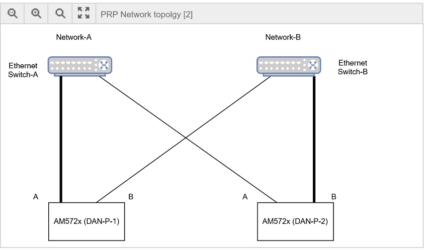
For Testing PRP, user is required to use the setup shown in the above diagram. A DAN-P is attached to two independent networks (A and B) each of which is shown as a separate Ethernet switch. Do the following steps to setup the prp interface. Note that in the below example Linux interface eth2 is Link-A (slave1 in ip link command) and eth3 is Link-B (slave2 in ip link command). Link-A is the Ethernet cable that connects DUT to Switch A and Link-B is the Ethernet cable that connects to Switch-B. This is very important for PRP as swapping them is an incorrect connection and can produce undesirable results.
- Connect the DAN-P-1 EVM, PRU2ETH0 (marking on EVM) to a port at Ethernet switch A and PRU2ETH1 to a port at Ethernet switch B
- Similarly, connect DAN-P-2 EVM, PRU2ETH0 to a port at Ethernet switch A and PRU2ETH1 to a port at Ethernet switch B
- Configure the PRU to load PRP firmware by setting env variable as discussed at Testing HSR/PRP Firmware Offload
- Boot the EVMs using the pre-built images from the Processor SDK release. These images are built with Linux HSR/PRP driver enabled. Login to the console using root user name.
- This time user may use the script (setup.sh) to create the prp interface. Note the MAC-A and MAC-B as in the case of HSR (MAC address of eth2)
- setup the prp interface at DAN-P-1 as follows
- /setup.sh prp <MAC-A> <IP Address of prp interface>
- setup the prp interface at DAN-P-2 as follows:-
- /setup.sh prp <MAC-B> <IP Address of prp interface>
If PRP interface uses IP address 192.168.2.20 and eth2 MAC address is 70:ff:76:1c:0f:8d, following example command may be used at DAN-P-1
/setup.sh prp 70:ff:76:1c:0f:8d 192.168.2.20
If PRP interface uses IP address 192.168.2.30 and eth2 MAC address is 70:ff:76:1c:0f:8e following example command may be use at DAN-P-2
/setup.sh prp 70:ff:76:1c:0f:8e 192.168.2.30
To teardown the prp interface do
/teardown.sh prp
Sample logs are shown below:
DAN-P-1
root@am57xx-evm:~# ifconfig eth2
eth2      Link encap:Ethernet  HWaddr 70:FF:76:1C:0F:8D
          inet6 addr: fe80::72ff:76ff:fe1c:f8d%3068183320/64 Scope:Link
          UP BROADCAST RUNNING MULTICAST  MTU:1500  Metric:1
          RX packets:80429 errors:0 dropped:0 overruns:0 frame:593
          TX packets:40905 errors:0 dropped:0 overruns:0 carrier:0
          collisions:0 txqueuelen:1000
          RX bytes:121704175 (116.0 MiB)  TX bytes:2716445 (2.5 MiB)

root@am57xx-evm:~# /setup.sh prp 70:FF:76:1C:0F:8D 192.168.2.20
Setting up prp0 interface with MAC address 70:FF:76:1C:0F:8D for slaves and IP address
192.168.2.20
[21649.978346] ti-pruss 4b280000.pruss: unconfigured system_events = 0x0000060000500000
host_intr = 0x00000115
[21649.988138]  remoteproc6: stopped remote processor 4b2b4000.pru0
[21649.994196] net eth2: stopped
[21650.048408] ti-pruss 4b280000.pruss: unconfigured system_events = 0x0060000000a00000
host_intr = 0x0000022a
[21650.058199]  remoteproc7: stopped remote processor 4b2b8000.pru1
[21650.064258] net eth3: stopped
[21650.084733]  remoteproc6: powering up 4b2b4000.pru0
[21650.090419]  remoteproc6: Booting fw image ti-pruss/am57xx-pru0-prueth-fw.elf, size 4350
[21650.098711] ti-pruss 4b280000.pruss: configured system_events = 0x0000060000500000
intr_channels = 0x00000095 host_intr = 0x00000115
[21650.110746]  remoteproc6: remote processor 4b2b4000.pru0 is now up
[21650.117709] net eth2: started
[21650.121113] IPv6: ADDRCONF(NETDEV_UP): eth2: link is not ready
[21650.131268]  remoteproc7: powering up 4b2b8000.pru1
[21650.136538]  remoteproc7: Booting fw image ti-pruss/am57xx-pru1-prueth-fw.elf, size 4382
[21650.144871] ti-pruss 4b280000.pruss: configured system_events = 0x0060000000a00000
intr_channels = 0x0000012a host_intr = 0x0000022a
[21650.156838]  remoteproc7: remote processor 4b2b8000.pru1 is now up
[21650.163795] net eth3: started
[21650.167169] IPv6: ADDRCONF(NETDEV_UP): eth3: link is not ready
[21650.188520] IPv6: ADDRCONF(NETDEV_CHANGE): eth2: link becomes ready
[21650.248510] device eth2 entered promiscuous mode
[21650.287995] device eth3 entered promiscuous mode
[21650.328127] IPv6: ADDRCONF(NETDEV_CHANGE): eth3: link becomes ready

root@am57xx-evm:~# ping 192.168.2.30
PING 192.168.2.30 (192.168.2.30): 56 data bytes
64 bytes from 192.168.2.30: seq=0 ttl=64 time=0.401 ms
64 bytes from 192.168.2.30: seq=1 ttl=64 time=0.189 ms
64 bytes from 192.168.2.30: seq=2 ttl=64 time=0.186 ms
^C
--- 192.168.2.30 ping statistics ---
3 packets transmitted, 3 packets received, 0% packet loss
round-trip min/avg/max = 0.186/0.258/0.401 ms
root@am57xx-evm:~#
root@am57xx-evm:~#
root@am57xx-evm:~#
root@am57xx-evm:~# iperf -s
------------------------------------------------------------
Server listening on TCP port 5001
TCP window size: 85.3 KByte (default)
------------------------------------------------------------
[  4] local 192.168.2.20 port 5001 connected with 192.168.2.30 port 38900
[ ID] Interval       Transfer     Bandwidth
[  4]  0.0-10.0 sec   109 MBytes  91.5 Mbits/sec
^Croot@am57xx-evm:~# iperf -s  -u
------------------------------------------------------------
Server listening on UDP port 5001
Receiving 1470 byte datagrams
UDP buffer size:  160 KByte (default)
------------------------------------------------------------
[  3] local 192.168.2.20 port 5001 connected with 192.168.2.30 port 43497
[ ID] Interval       Transfer     Bandwidth        Jitter   Lost/Total Datagrams
[  3]  0.0-10.0 sec   106 MBytes  88.8 Mbits/sec   0.070 ms  583/76109 (0.77%)
[  3]  0.0-10.0 sec  1 datagrams received out-of-order
^Croot@am57xx-evm:~#
root@am57xx-evm:~#
root@am57xx-evm:~#
root@am57xx-evm:~# cat /sys/kernel/debug/prp/stats
Stats entries
cnt_tx_a = 40864
cnt_tx_b = 40864
cnt_tx_c = 40801
cnt_rx_wrong_lan_a = 8
cnt_rx_wrong_lan_b = 0
cnt_rx_a = 230882
cnt_rx_b = 230878
cnt_rx_c = 230746
cnt_rx_errors_a = 0
cnt_rx_errors_b = 0

root@am57xx-evm:~# cat /sys/kernel/debug/prp/node_table
Node Table entries
MAC-Address-A,   MAC-Address-B, time_in[A], time_in[B], Address-B port, san_a, san_b
11:ff:fe:80:00:00: 00:00:00:00:00:00:0x209604, 0x20964b 0x0, 1, 0
2a:da:8c:50:1b:86: 00:00:00:00:00:00:0x20c78e, 0x20c78e 0x0, 0, 0
DAN-P-2
root@am57xx-evm:~# ifconfig eth2
eth2      Link encap:Ethernet  HWaddr 2A:DA:8C:50:1B:86
         inet6 addr: fe80::28da:8cff:fe50:1b86%3068203800/64 Scope:Link
         UP BROADCAST RUNNING MULTICAST  MTU:1500  Metric:1
         RX packets:40881 errors:0 dropped:10 overruns:0 frame:64
         TX packets:81022 errors:0 dropped:3528075 overruns:0 carrier:0
         collisions:0 txqueuelen:1000
         RX bytes:2718950 (2.5 MiB)  TX bytes:122601929 (116.9 MiB)

root@am57xx-evm:~# /setup.sh prp 2A:DA:8C:50:1B:86 192.168.2.30
Setting up prp0 interface with MAC address 2A:DA:8C:50:1B:86 for slaves and IP address
192.168.2.30
[21684.048303] ti-pruss 4b280000.pruss: unconfigured system_events = 0x0000060000500000
host_intr = 0x00000115
[21684.058095]  remoteproc6: stopped remote processor 4b2b4000.pru0
[21684.064152] net eth2: stopped
[21684.118368] ti-pruss 4b280000.pruss: unconfigured system_events = 0x0060000000a00000
host_intr = 0x0000022a
[21684.128160]  remoteproc7: stopped remote processor 4b2b8000.pru1
[21684.134217] net eth3: stopped
[21684.158347]  remoteproc6: powering up 4b2b4000.pru0
[21684.164069]  remoteproc6: Booting fw image ti-pruss/am57xx-pru0-prueth-fw.elf, size 4350
[21684.172524] ti-pruss 4b280000.pruss: configured system_events = 0x0000060000500000
intr_channels = 0x00000095 host_intr = 0x00000115
[21684.184563]  remoteproc6: remote processor 4b2b4000.pru0 is now up
[21684.191761] net eth2: started
[21684.195184] IPv6: ADDRCONF(NETDEV_UP): eth2: link is not ready
[21684.205638]  remoteproc7: powering up 4b2b8000.pru1
[21684.210960]  remoteproc7: Booting fw image ti-pruss/am57xx-pru1-prueth-fw.elf, size 4382
[21684.219252] ti-pruss 4b280000.pruss: configured system_events = 0x0060000000a00000
intr_channels = 0x0000012a host_intr = 0x0000022a
[21684.231220]  remoteproc7: remote processor 4b2b8000.pru1 is now up
[21684.238235] net eth3: started
[21684.241684] IPv6: ADDRCONF(NETDEV_UP): eth3: link is not ready
[21684.339123] device eth2 entered promiscuous mode
[21684.377962] device eth3 entered promiscuous mode
[21684.425802] prp0: Slave A (eth2) is not up; please bring it up to get a fully working HSR
network
[21684.436772] IPv6: ADDRCONF(NETDEV_UP): prp0: link is not ready
[21684.443615] IPv6: ADDRCONF(NETDEV_CHANGE): prp0: link becomes ready
root@am57xx-evm:~# [21684.488601] IPv6: ADDRCONF(NETDEV_CHANGE): eth2: link becomes ready
[21684.518615] IPv6: ADDRCONF(NETDEV_CHANGE): eth3: link becomes ready

root@am57xx-evm:~# iperf -c 192.168.2.20
------------------------------------------------------------
Client connecting to 192.168.2.20, TCP port 5001
TCP window size: 43.8 KByte (default)
------------------------------------------------------------
[  3] local 192.168.2.30 port 38900 connected with 192.168.2.20 port 5001
[ ID] Interval       Transfer     Bandwidth
[  3]  0.0-10.0 sec   109 MBytes  91.5 Mbits/sec
root@am57xx-evm:~# iperf -c 192.168.2.20 -u -b 90M
------------------------------------------------------------
Client connecting to 192.168.2.20, UDP port 5001
Sending 1470 byte datagrams
UDP buffer size:  160 KByte (default)
------------------------------------------------------------
[  3] local 192.168.2.30 port 43497 connected with 192.168.2.20 port 5001
[ ID] Interval       Transfer     Bandwidth
[  3]  0.0-10.0 sec   107 MBytes  89.5 Mbits/sec
[  3] Sent 76110 datagrams
[  3] Server Report:
[  3]  0.0-10.0 sec   106 MBytes  88.8 Mbits/sec   0.069 ms  583/76109 (0.77%)
[  3]  0.0-10.0 sec  1 datagrams received out-of-order
root@am57xx-evm:~#  cat /sys/kernel/debug/prp/stats
Stats entries
cnt_tx_a = 232489
cnt_tx_b = 232488
cnt_tx_c = 232437
cnt_rx_wrong_lan_a = 0
cnt_rx_wrong_lan_b = 0
cnt_rx_a = 40822
cnt_rx_b = 40822
cnt_rx_c = 40757
cnt_rx_errors_a = 0
cnt_rx_errors_b = 0

root@am57xx-evm:~# cat /sys/kernel/debug/prp/node_table
Node Table entries
MAC-Address-A,   MAC-Address-B, time_in[A], time_in[B], Address-B port, san_a, san_b
70:ff:76:1c:0f:8d: 00:00:00:00:00:00:0x20cd1b, 0x20cd1b 0x0, 0, 0
11:ff:fe:80:00:00: 00:00:00:00:00:00:0x20a393, 0x20a38c 0x0, 0, 1
4.2.3.10. Performance Test and Logs
Boot up two AM571x/572x EVM to configure PRU Ethernet in HSR or PRP mode as described at Testing HSR/PRP Firmware Offload They are connected over eth2 and eth3 as described in HSR Testing or PRP Testing
UDP
Sample iperf UDP test showing no packet loss for MTU sized packets. For HSR/PRP, there are 6 bytes of Tag effectively reducing pay load size to 1466 (1500 - 6 - 20 - 8)
Server Side
root@am57xx-evm:~# iperf -s -u
------------------------------------------------------------
Server listening on UDP port 5001
Receiving 1470 byte datagrams
UDP buffer size:  160 KByte (default)
------------------------------------------------------------
[  3] local 192.168.2.20 port 5001 connected with 192.168.2.30 port 34255
[ ID] Interval       Transfer     Bandwidth        Jitter   Lost/Total Datagrams
[  3]  0.0-60.0 sec   630 MBytes  88.1 Mbits/sec   0.002 ms    0/450887 (0%)
[  3]  0.0-60.0 sec  1 datagrams received out-of-order
Client side
root@am57xx-evm:~# iperf -c 192.168.2.20 -u -b88M -l1466 -t60
------------------------------------------------------------
Client connecting to 192.168.2.20, UDP port 5001
Sending 1466 byte datagrams
UDP buffer size:  160 KByte (default)
------------------------------------------------------------
[  3] local 192.168.2.30 port 34255 connected with 192.168.2.20 port 5001
[ ID] Interval       Transfer     Bandwidth
[  3]  0.0-60.0 sec   630 MBytes  88.1 Mbits/sec
[  3] Sent 450888 datagrams
[  3] Server Report:
[  3]  0.0-60.0 sec   630 MBytes  88.1 Mbits/sec   0.002 ms    0/450887 (0%)
[  3]  0.0-60.0 sec  1 datagrams received out-of-order
NOTE: When doing UDP test, user may observe out of order packets sometimes. This is normal as the driver doesn’t use NAPI and packets may get queued to backlog queues of each CPU which may get delivered out of sequence to the iperf application. Out of order delivery of UDP packets are normal and kernel doesn’t guarantee in sequence delivery of UDP packets to application. So iperf may show some packets lost during the test. User may use some of the tools available to migrate the rx irq threads and iperf server to same CPU, example CPU 0, to mitigate out of order issue and get a no loss iperf stats for udp tests.
For example, here is a snapshot of the test that shows packet lost during the test. The test also shows 106 datagram received out of order.
root@am57xx-evm:~# iperf -s -u
------------------------------------------------------------
Server listening on UDP port 5001
Receiving 1470 byte datagrams
UDP buffer size:  160 KByte (default)
------------------------------------------------------------
[  3] local 192.168.2.30 port 5001 connected with 192.168.2.20 port 41976
[ ID] Interval       Transfer     Bandwidth        Jitter   Lost/Total Datagrams
[  3]  0.0-600.0 sec  6.15 GBytes  88.0 Mbits/sec   0.004 ms    5/4501411 (0.00011%)
[  3]  0.0-600.0 sec  106 datagrams received out-of-order
Run the iperf -s -u & Do ps command and find the PID of the iperf and migrate the process to CPU 0 as follows
root@am57xx-evm:~# ps
 PID TTY          TIME CMD
 964 ttyS2    00:00:00 login
1063 ttyS2    00:00:00 sh
1135 ttyS2    00:00:00 iperf
1141 ttyS2    00:00:00 ps
root@am57xx-evm:~# taskset -cp 0 1135
pid 1135's current affinity list: 0,1
pid 1135's new affinity list: 0
Now find the irq thread for eth2, eth3 devices using
root@am57xx-evm:~# ps -ef  | grep "eth3"
root      1464     2  0 06:01 ?        00:00:00 [irq/498-eth3]
root      1495  1065  0 06:04 ttyS2    00:00:00 grep irq/498-eth3
root@am57xx-evm:~# ps -ef  | grep "eth2"
root      1462     2  0 06:01 ?        00:00:00 [irq/496-eth2]
root      1497  1065  0 06:04 ttyS2    00:00:00 grep irq/496-eth2
In the above example 1462 is the process id of irq/496-eth2 thread and 1464 is the process ID of irq/498-eth3 . Do following to migrate them to CPU 0.
root@am57xx-evm:~# taskset -cp 0 1464
pid 1464's current affinity list: 0,1
pid 1464's new affinity list: 0
root@am57xx-evm:~# taskset -cp 0 1462
pid 1462's current affinity list: 0,1
pid 1462's new affinity list: 0
root@am57xx-evm:~#
root@am57xx-evm:~#
Now start iperf client on the other side. The server side log below with these tuning shows no packet loss.
[  4] local 192.168.2.30 port 5001 connected with 192.168.2.20 port 36415
[  4]  0.0-600.0 sec  6.15 GBytes  88.0 Mbits/sec   0.007 ms    0/4501355 (0%)
[  4]  0.0-600.0 sec  1 datagrams received out-of-order
| Packet Size | Tput with no packet loss (Mbits/sec) |
|---|---|
| 1466 | 88 |
| 1024 | 88 |
| 512 | 64 |
| 256 | 45 |
Table: UDP Performance for HSR
| Packet Size | Tput with no packet loss (Mbits/sec) |
|---|---|
| 1466 | 88 |
| 1024 | 88 |
| 512 | 60 |
| 256 | 38 |
Table: UDP Performance for PRP
NOTE-1:Test ran for 1 minute with single direction traffic (Client to Server). Reduced the traffic from 88Mbits/sec until there is no out of order or lost packets in the iperf stats
TCP
HSR
Server side
root@am57xx-evm:~# iperf -s
------------------------------------------------------------
Server listening on TCP port 5001
TCP window size: 85.3 KByte (default)
------------------------------------------------------------
[  4] local 192.168.2.20 port 5001 connected with 192.168.2.30 port 54148
[ ID] Interval       Transfer     Bandwidth
[  4]  0.0-60.0 sec   663 MBytes  92.7 Mbits/sec
Client side
root@am57xx-evm:~# iperf -c 192.168.2.20  -t60
------------------------------------------------------------
Client connecting to 192.168.2.20, TCP port 5001
TCP window size: 43.8 KByte (default)
------------------------------------------------------------
[  3] local 192.168.2.30 port 54148 connected with 192.168.2.20 port 5001
[ ID] Interval       Transfer     Bandwidth
[  3]  0.0-60.0 sec   663 MBytes  92.7 Mbits/sec
PRP
Server side
root@am57xx-evm:~# iperf -s
------------------------------------------------------------
Server listening on TCP port 5001
TCP window size: 85.3 KByte (default)
------------------------------------------------------------
[  4] local 192.168.2.20 port 5001 connected with 192.168.2.30 port 54150
[ ID] Interval       Transfer     Bandwidth
[  4]  0.0-60.0 sec   660 MBytes  92.3 Mbits/sec
Client side
root@am57xx-evm:~# iperf -c 192.168.2.20 -t60
------------------------------------------------------------
Client connecting to 192.168.2.20, TCP port 5001
TCP window size: 43.8 KByte (default)
------------------------------------------------------------
[  3] local 192.168.2.30 port 54150 connected with 192.168.2.20 port 5001
[ ID] Interval       Transfer     Bandwidth
[  3]  0.0-60.0 sec   660 MBytes  92.3 Mbits/sec
4.2.3.11. Redundancy Test and Logs
For HSR and PRP redundancy is implemented using duplicate links and sending frame over both links and discarding the duplicate at the receive side. The test requires two DAN-P or DAN-H nodes connected over eth2 and eth3 Ethernet Links. Boot up the EVM with bootargs set to configure PRU Ethernet in HSR or PRP mode as described at Processor_SDK_Linux_HSR_PRP#Testing_HSR.2FPRP_Firmware_Offload Do an iperf UDP test at 88Mbits/sec for MTU sized packets (size = 1466) and then pull out either eth2 or eth3 Ethernet cable. Make sure iperf stats doesn’t show packet loss during the test period. Here is the log for HSR that show link failed during the test and there was no packet loss.
eth3 link failed
root@am57xx-evm:~# iperf -c 192.168.2.20 -u -b88M -l1466 -t60
------------------------------------------------------------
Client connecting to 192.168.2.20, UDP port 5001
Sending 1466 byte datagrams
UDP buffer size:  160 KByte (default)
------------------------------------------------------------
[  3] local 192.168.2.30 port 50443 connected with 192.168.2.20 port 5001
[  108.740402] prueth pruss2_eth eth3: Link is Down
[ ID] Interval       Transfer     Bandwidth
[  3]  0.0-60.0 sec   631 MBytes  88.2 Mbits/sec
[  3] Sent 451002 datagrams
[  3] Server Report:
[  3]  0.0-60.0 sec   631 MBytes  88.2 Mbits/sec   0.003 ms    0/451001 (0%)
[  3]  0.0-60.0 sec  1 datagrams received out-of-order
root@am57xx-evm:~# [  181.444988] prueth pruss2_eth eth3: Link is Up - 100Mbps/Full - flow control off
eth2 link failed
root@am57xx-evm:~# iperf -c 192.168.2.20 -u -b88M -l1466 -t60
------------------------------------------------------------
Client connecting to 192.168.2.20, UDP port 5001
Sending 1466 byte datagrams
UDP buffer size:  160 KByte (default)
------------------------------------------------------------
[  3] local 192.168.2.30 port 49260 connected with 192.168.2.20 port 5001
[  204.253286] prueth pruss2_eth eth2: Link is Down
[ ID] Interval       Transfer     Bandwidth
[  3]  0.0-60.0 sec   631 MBytes  88.2 Mbits/sec
[  3] Sent 451028 datagrams
[  3] Server Report:
[  3]  0.0-60.0 sec   631 MBytes  88.2 Mbits/sec   0.005 ms    0/451027 (0%)
[  3]  0.0-60.0 sec  1 datagrams received out-of-order
root@am57xx-evm:~# uname -a
Linux am57xx-evm 4.9.41-rt23-gc038d21a22 #2 SMP PREEMPT RT Wed Sep 27 06:34:09 EDT 2017 armv7l GNU/Linux
4.2.3.12. Useful Commands
For Non offload case following commands are available. To dump stats
- cat /sys/kernel/debug/hsr/stats
To dump Node_Table
- cat /sys/kernel/debug/hsr/node_table
For PRP, replace hsr in the above paths with prp
For Offloaded case following commands are available to change mode To change HSR mode do both commands below.
- echo 1 > /sys/kernel/debug/hsr/hsr_mode
- echo 1 > /sys/kernel/debug/prueth-prp/hsr_mode
To see the node table entries for offloaded case, do
- cat /sys/kernel/debug/prueth-prp/new_nt_bins
or
- cat /sys/kernel/debug/prueth-hsr/new_nt_bins
where 1 is for Mode-H
Other values are 2 (Mode-N), 3 (Mode-T), 4 (Mode-U), 5 (Mode-M)
4.2.3.13. FAQ
- How to disable udhcpc from sending DHCP request over prueth Ethernet interfaces (eth2-eth3) when it is configured to run HSR/PRP protocol in firmware?
Linux HSR/PRP driver uses the eth2/eth3 interface as slave interfaces to implement the protocol on top of it. Application is expected to send or receive packets over the hsr or prp lre interface also known as C port. However prueth also support plain Ethernet and the file system /etc/systemd/network/10-eth.network has a general rule to enable DHCP over all of the interface matching eth*. Modify the file to match unique name instead of generic name wild cards. For example to do DHCP over only eth0 interface, 10-eth.network may be modified as follows:-
root@am57xx-evm:~# cat /etc/systemd/network/10-eth.network
[Match]
Name=eth0
KernelCommandLine=!root=/dev/nfs

[Network]
DHCP=yes
To do DHCP over hsr0 or prp0 interfaces, user may add additional files to /etc/systemd/network/ one for each prp0 or hsr0 similar to eth0, by using a Match name string of hsr0 or prp0. More details on this is at [[6]]
4.3. PTP
4.3.1. Overview
The Precision Time Protocol (PTP), defined in IEEE 1588, is a protocol used to synchronize clocks throughout a network. Many applications in Industrial automation, Grid Infrastructure, Motion Control, AVB, and Telecom markets require nano-second accuracy/precision, varied update rates, rapid reconfiguration after network changes, fault tolerance. TI’s Sitara hardware platforms have dedicated hardware/firmware that help us meet these stringent requirements for synchronizing the distributed real-time clocks, in conjunction with LinuxPTP Application Stack. This page is specific to the PTP implementation in Linux, and the following sections provide details about the Software Architecture, Supported platforms, test setup and details about the support for Ordinary Clock (OC), Boundary Clock (BC) And Transparent Clock (TC)
4.3.2. Software Overview
The picture below shows the Linux software stack of HSR/PRP/PTP in Processor SDK.
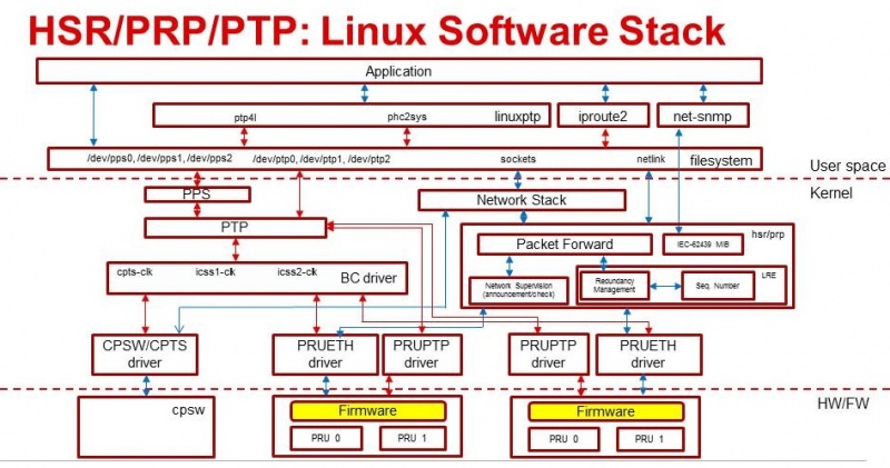
4.3.2.1. Software Components
- PRUETH driver – Kernel driver abstracts PRU hardware/firmware
- PRUPTP driver – Kernel driver abstracts PRU-ICSS based PTP support
- CPTS driver - Kernel driver abstracts CPSW/CPTS based PTP support
- BC driver – Responsible for port state changes, IO Pad configuration
- HSR/PRP driver – Upstream HSR driver, with PRP support and additional bug fixes
- iproute2 - a collection of userspace utilities for controlling and monitoring various aspects of networking in the Linux kernel, including routing, network interfaces, tunnels, traffic control, and network-related device drivers
- net-snmp - a suite of software for using and deploying the SNMP protocol
- linuxptp (ptp4l, phc2sys)
- Filesystem (/dev/ppsX, /dev/ptpX)
4.3.2.2. linuxptp Overview
The Linux PTP Project is a software implementation of the PTP according to the IEEE 1588 Standard. This software is licensed under GNU GPL License, as described in the Processor SDK Software Manifest. For more details on Linux PTP framework and implementation refer: https://linuxptp.sourceforge.net/
LinuxPTP provides the four user applications - ptp4l, phc2sys, hwstamp_ctl and pmc. The definition and usage of these applications is as follows:
- ptp4l: It is the main program that implements the Precision Time Protocol (PTP) according to IEEE standard 1588 for Linux, as a Boundary Clock (BC) and Ordinary Clock (OC). The ‘slave’ and ‘master’ roles are determined for each port automatically using the BMC
- phc2sys: It is a utility program to synchronize the normal Linux system time to a PTP Hardware Clock - which itself is synchronized by the ptp4l program/application. For phc2sys, the terms ‘slave’ and ‘master’ are not about the PTP, but rather about two local clocks. Usually, the Linux system time is the slave, and the PHC is the master.
- pmc: This is a utility program for sending PTP management queries. The program reads from the standard input actions specified by name and management ID, sends them over the selected transport and prints any received replies.
- hwstamp_ctl: It is just a test program for the SIOCSHWTSTAMP ioctl, used for debugging. The ptp4l program does not need this program to function
TI has forked LinuxPTP to add support for Sitara family of devices, and the repo is hosted here: https://git.ti.com/processor-sdk/linuxptp
4.3.3. Hardware Overview
TI’s Sitara devices have support for GMAC and PRU-ICSS ports, as shown in the table below.
| SoC | # of GMAC ports | # of PRU-ICSS ports |
|---|---|---|
| AM571x | 1 | 2(at 100Mbps) |
| AM572x | 1 | 1(at 100Mbps) |
| AM574x | 1 | 2(at 100Mbps) |
4.3.3.1. GMAC
GMAC interface can be configured to run at either 100 Mbps or 1 Gbps. CPTS hardware block helps with timestamping of packets. Refer to Common Platform Time Sync (CPTS) module for details.
4.3.3.2. PRU-ICSS
The processing load is shared between firmware (PRU) and Host (ARM) with the firmware doing most of the time critical activities. The IEP hardware block in the PRU-ICSS sub-system is responsible for timestamping of packets. Memory map for the firmware interface can be found in HSR/PRP Memory Map.
4.3.3.3. Hardware Modifications
- Hardware modifications are required on the AM57xx IDK platforms to provide access points to 1 PPS sync and latch signals for CPSW/CPTS and PRU-ICSS modules
- For Boundary Clock, since PPS generated by one internal clock needs to be latched into another internal clock, hardware, mainly blue wire, modifications are needed in order to achieive the latching of the PPS generated by one internal clock into another internal clock.
Please refer to AM571x-IDK modifications and AM572x-IDK modifications documents and make the recommended changes to verify OC and BC, and to get access to 1 PPS signals
4.3.4. Generating 1 PPS
The PPS (Pulse Per Second) or 1PPS signal is an electrical signal that has a width of less than one second and a sharply rising or abruptly falling edge at the second boundary. The PPS signal can be used to measure the offset and jitters of the system time between the master and slave clock. This signal can also be used to synchronize the slave clock to its master within a BC.
4.3.4.1. PRU-ICSS
IEP has an additional hardware to generate a programmable sync output which is tied to the IEP counter. This is called the SYNC unit. For this signal generation CMP1 is programmed to a value of 1 second. A HIT event is generated by PRU0. Linux PRUETH IEP driver checks this event in and re-programs CMP1 after every hit to ensure that accurate sync pulses are generated. This sync is equivalent to the 1PPS output and should not be confused with PTP Sync frame.
To enable/disable 1PPS signal on PRU-ICSS port, enter the following commands respectively
echo 1 > /sys/devices/platform/pruss2_eth/ptp/ptp1/pps_enable
echo 0 > /sys/devices/platform/pruss2_eth/ptp/ptp1/pps_enable
or
echo 1 > /sys/devices/platform/pruss2_eth/ptp/ptp2/pps_enable
echo 0 > /sys/devices/platform/pruss2_eth/ptp/ptp2/pps_enable
echo 1 > /sys/devices/platform/pruss1_eth/ptp/ptp2/pps_enable
echo 0 > /sys/devices/platform/pruss1_eth/ptp/ptp2/pps_enable
or
echo 1 > /sys/devices/platform/pruss1_eth/ptp/ptp1/pps_enable
echo 0 > /sys/devices/platform/pruss1_eth/ptp/ptp1/pps_enable
Please note that both ptp1/2 may be assigned to pruss1(2)_eth based on the order of operations. Use the following command to find out the assigned PTP ports.
ls /sys/devices/platform/pruss1_eth/ptp
ls /sys/devices/platform/pruss2_eth/ptp
4.3.4.2. GMAC
The GMAC/CPTS does not support a programmable sync output. Instead, the GP Timer16 can be programmed to generate an output pulse every 100ms or second and then this signal is passed to CPTS/HW_TS_PUSH4 to trigger the HW_TS_PUSH event. Linux CPSW/CPTS driver checks this event in and run through a simple algorithm to adjust the GP Timer reload value after every hit to ensure that output sync pulse is aligned at the second boundary of the PTP system time. In order to satisfy the +/-50ns jitter requirement by reducing the accumulation error, the current 1PPS implementation will generate a output pulse every 100ms and 9 out of 10 pulses will be filtered out except the one at the second boundary through the pad-config or GPIO-based output control.
To enable/disable 1PPS signal on GMAC/CPTS, enter the following command respectively:
echo 1 > /sys/devices/platform/44000000.ocp/48484000.ethernet/ptp/ptp0/pps_enable
echo 0 > /sys/devices/platform/44000000.ocp/48484000.ethernet/ptp/ptp0/pps_enable
4.3.4.3. PPS Output Latency Configuration
It should be possible to configure the latency of the 1PPS output of GMAC, PRU_ICSS to compensate for local propagation delay or for testing purpose. A new PTP interface has been defined and implemented to allow the PPS output latency to be adjusted in unit of ns.
The PPS output latency adjustment called PPS Offset can be set through the command interface or as the port configuration parameter of linuxptp.
To set PPS offset to -10ns on PRU-ICSS port, enter the following command:
echo -10 > /sys/devices/platform/pruss2_eth/ptp/ptp1/pps_offset
To set PPS offset to 10ns on GMAC/CPTS port, enter the following command:
echo 10 > /sys/devices/platform/44000000.ocp/48484000.ethernet/ptp/ptp0/pps_offset
To configure the PPS offset of eth2 to 20ns, add the following line to the OC/BC configuration file
[eth2]
ppsOffset 20
4.3.5. PTP Ordinary Clock
PTP ordinary clock (OC) is supported on both the CPSW GMAC ports and the PRU-ICSS ports.
The IEEE-1588-2009 standard defines ordinary clock as “A clock that has a single Precision Time Protocol (PTP) port in a domain and maintains the timescale used in the domain. It may serve as a source of time, i.e., be a master clock, or may synchronize to another clock, i.e., be a slave clock.”
At the heart of the ordinary clock support is the capability of being able to timestamp the PTP event messages that passes through the different Ethernet ports. It is the CPTS module that does the timestamping for the CPSW GMAC ports. For PRU-ICSS ports, it is the IEP module together with the PRU firmware that does the timestamping.
PHY Delay Compensation
The IEEE1588 timestamp should be measured at the Ethernet wire and therefore the ideal place to measure the egress/ingress timestamp of the Ethernet packets is at the Ethernet PHY. Unfortunately it is usually not the case. The delay between the actual timestamp location and the ideal location at the Ethernet wire will add to the path delay and create error of the path delay and offset of the system timestamp if the egress and ingress delay is not symmetric.
The Linux PTP software stack is designed to handle those delays with environment variable egressLatency and ingressLatency. Both delay number should be calculated or measured and used at the PTP configuration file. In the case that those two number are not available, use the following formulas to adjust those two variables as long as the measured path delay by Linux PTP is positive.
To reduce the 1PPS offset by x, increase the asymmetry delay compensation by 2x
To reduce the end-to-end delay by y, increase both ingressLatency and egressLatency by y.
4.3.5.1. PTP Ordinary Clock on PRU-ICSS
Timestamping of PTP event messages at the PRU-ICSS ports is provided by the PRU-ICSS IEP module together with the PRU firmware. More precisely, the PRU-PRP firmware is used and is configured in SAN (Single Attached Node) mode.
In this Linux PRU-ICSS OC implementation, the PRU firmware stores timestamps (IEP counter values) of PTP event messages in specific shared memory locations. The PRU IEP driver retrieves the timestamps and converts them into PTP time values (in nanoseconds) before they are passed to upper layer for further processing. The current PRU-ICSS PTP clock frequency and time scale are kept in the IEP driver.
Since the PRU IEP drivers implements the Linux PTP hardware clock subsystem APIs, the PRU-ICSS PTP clock can therefore be adjusted by using those standard APIs. See PTP hardware clock infrastructure for Linux for more details.
The PTP OC protocol is provided by the linuxptp application.
Follow the steps at PRP EMAC mode to boot up the AM57xx IDK and configure the PRU-PRP firmware to run in PRP_EMAC mode. Once the AM57xx IDK is boot into Linux kernel prompt and the PRU-ICSS Ethernet ports are properly configured, to run linuxptp over the PRU-ICSS Ethernet ports, do
ptp4l -2 -P -f oc.cfg
oc.cfg is a ptp4l configuration file.
Example oc.cfg for OC,
[global]
tx_timestamp_timeout 10
logMinPdelayReqInterval -3
logSyncInterval -3
twoStepFlag 1
summary_interval 0
[eth2]
egressLatency 726
ingressLatency 186
where eth2 is the intended PRU-ICSS Ethernet port over which the OC functionality is provided.
See The Linux PTP Project for more details about linuxptp in general and ptp4l(8) - Linux man page about ptp4l configurations in particular.
Here is a sample screen display of ptp4l for PRU-ICSS Ethernet port as PTP/OC in slave mode:
ptp4l -2 -P -f oc_eth2.txt -s -m &
[1] 1153
root@am57xx-evm:~# ptp4l[3777.676]: selected /dev/ptp1 as PTP clock
ptp4l[3777.740]: port 1: INITIALIZING to LISTENING on INIT_COMPLETE
ptp4l[3777.743]: port 0: INITIALIZING to LISTENING on INIT_COMPLETE
ptp4l[3777.744]: port 1: received PDELAY_REQ without timestamp
ptp4l[3778.727]: port 1: new foreign master 8ca5a1.fffe.0000c2-1
ptp4l[3782.727]: selected best master clock 8ca5a1.fffe.0000c2
ptp4l[3782.727]: port 1: LISTENING to UNCALIBRATED on RS_SLAVE
ptp4l[3783.028]: port 1: UNCALIBRATED to SLAVE on MASTER_CLOCK_SELECTED
ptp4l[3783.653]: rms 756344481817248256 max 1512688963634496512 ( -31, 1512688963634496512) freq  +2319 +/- 877 delay    12 +/-   0
ptp4l[3784.653]: rms   28 max   32 ( -32,  -22) freq  +2612 +/-   9 delay    12 +/-   0
ptp4l[3785.778]: rms   16 max   24 ( -24,  -11) freq  +2604 +/-   3 delay    12 +/-   0
ptp4l[3786.778]: rms    6 max    9 (  -9,   -1) freq  +2607 +/-   3 delay    12 +/-   1
ptp4l[3787.904]: rms    3 max    6 (  -6,    4) freq  +2612 +/-   5 delay    12 +/-   0
ptp4l[3788.904]: rms    6 max   11 (   4,   11) freq  +2624 +/-   2 delay    12 +/-   0
ptp4l[3789.904]: rms    4 max    7 (  -2,    7) freq  +2621 +/-   5 delay    12 +/-   0
ptp4l[3790.904]: rms    5 max   10 ( -10,    2) freq  +2613 +/-   5 delay    11 +/-   0
ptp4l[3791.904]: rms    6 max   10 ( -10,    0) freq  +2606 +/-   4 delay    12 +/-   1
ptp4l[3792.904]: rms    3 max    6 (  -4,    6) freq  +2610 +/-   4 delay    11 +/-   1
ptp4l[3793.904]: rms    6 max   11 (   0,   11) freq  +2618 +/-   6 delay    12 +/-   0
ptp4l[3794.904]: rms    4 max    8 (  -5,    8) freq  +2618 +/-   5 delay    11 +/-   1
ptp4l[3796.029]: rms    3 max    6 (  -6,    4) freq  +2614 +/-   4 delay    12 +/-   1
ptp4l[3797.029]: rms    3 max    5 (  -5,    5) freq  +2614 +/-   4 delay    12 +/-   1
ptp4l[3798.030]: rms    2 max    4 (  -4,    3) freq  +2614 +/-   3 delay    12 +/-   0
ptp4l[3799.030]: rms    3 max    6 (  -4,    6) freq  +2616 +/-   4 delay    12 +/-   0
ptp4l[3800.030]: rms    3 max    5 (  -5,    5) freq  +2615 +/-   4 delay    10 +/-   0
ptp4l[3801.030]: rms    4 max    8 (  -8,    2) freq  +2609 +/-   5 delay    10 +/-   1
ptp4l[3802.030]: rms    7 max   12 ( -12,    3) freq  +2603 +/-   7 delay    11 +/-   0
ptp4l[3803.030]: rms    4 max    7 (  -7,    3) freq  +2601 +/-   4 delay    12 +/-   0
ptp4l[3804.030]: rms    4 max    7 (  -7,    4) freq  +2599 +/-   5 delay    13 +/-   1
ptp4l[3805.030]: rms    6 max    9 (  -8,    9) freq  +2600 +/-   8 delay    12 +/-   0
ptp4l[3806.030]: rms    5 max   10 (   0,   10) freq  +2609 +/-   4 delay    12 +/-   0
ptp4l[3807.030]: rms    5 max   10 ( -10,    6) freq  +2604 +/-   7 delay    12 +/-   0
ptp4l[3808.030]: rms    6 max    8 (  -8,   -1) freq  +2594 +/-   3 delay    11 +/-   0
ptp4l[3809.031]: rms    7 max   10 ( -10,   -2) freq  +2587 +/-   4 delay    12 +/-   1
ptp4l[3810.156]: rms    4 max    8 (  -8,    0) freq  +2587 +/-   4 delay    12 +/-   0
ptp4l[3811.156]: rms    2 max    4 (  -1,    4) freq  +2591 +/-   3 delay    12 +/-   1
ptp4l[3812.156]: rms    4 max    7 (  -2,    7) freq  +2596 +/-   4 delay    11 +/-   0
ptp4l[3813.406]: rms    3 max    6 (  -6,    1) freq  +2588 +/-   3 delay    12 +/-   0
ptp4l[3814.406]: rms    6 max    7 (  -7,    1) freq  +2582 +/-   5 delay    12 +/-   0
ptp4l[3815.406]: rms    4 max    7 (  -4,    7) freq  +2588 +/-   5 delay    11 +/-   0
ptp4l[3816.406]: rms    3 max    4 (  -4,    4) freq  +2587 +/-   4 delay    12 +/-   1
ptp4l[3817.531]: rms    4 max    6 (  -6,    6) freq  +2590 +/-   5 delay    12 +/-   1
ptp4l[3818.531]: rms    3 max    5 (  -5,    5) freq  +2587 +/-   4 delay    11 +/-   0
ptp4l[3819.532]: rms    4 max    5 (  -5,    4) freq  +2584 +/-   4 delay    12 +/-   0
ptp4l[3820.657]: rms    4 max    7 (  -1,    7) freq  +2592 +/-   3 delay    11 +/-   0
ptp4l[3821.782]: rms    4 max    9 (  -2,    9) freq  +2594 +/-   5 delay    11 +/-   0
ptp4l[3822.782]: rms    3 max    5 (  -5,    2) freq  +2589 +/-   4 delay    11 +/-   0
...
4.3.5.1.1. Some useful commands
To see the availability of ICSS-PRU1 and ICSS-PRU2 on SoC:
root@am57xx-evm:~# ls /sys/devices/platform/
and look for pruss1_eth and/or pruss2_eth.
To see which interface is configured under, for example, ICSS-PRU2:
root@am57xx-evm:~# ls /sys/devices/platform/pruss2_eth/net
eth2/ eth3/
To see what is available under an ICSS-PRU ptp support:
root@am57xx-evm:~# ls /sys/devices/platform/pruss2_eth/ptp
ptp1/
root@am57xx-evm:~# ls /sys/devices/platform/pruss2_eth/ptp/ptp1
clock_name             fifo                   n_periodic_outputs     pps_available
dev                    max_adjustment         n_programmable_pins    pps_enable
device@                n_alarms               period                 subsystem@
extts_enable           n_external_timestamps  power/                 uevent
root@am57xx-evm:~# cat /sys/devices/platform/pruss1_eth/ptp/ptp2/clock_name
PRUSS1 timer
root@am57xx-evm:~# cat /sys/devices/platform/pruss2_eth/ptp/ptp1/pps_available
1
If ptp4l is started in the background and without the “-m” option to print any message to standard output, the system log file /var/log/messages can be used to get a glimpse of the progress of ptp4l. For example,
root@am57xx-evm:~# ptp4l -2 -P -f oc.cfg &
root@am57xx-evm:~#
root@am57xx-evm:~# tail -n 30 /var/log/messages
Dec  5 20:45:14 am57xx-evm daemon.info thttpd[946]:   fdwatch - 729 polls (0.2025/sec)
Dec  5 20:45:14 am57xx-evm daemon.info thttpd[946]:   timers - 3 allocated, 3 active, 0 free
Dec  5 20:58:06 am57xx-evm user.notice ptp4l: [83598.805] selected best master clock 70ff76.fffe.1c0f99
Dec  5 20:58:06 am57xx-evm user.notice ptp4l: [83598.805] port 2: MASTER to UNCALIBRATED on RS_SLAVE
Dec  5 20:58:06 am57xx-evm user.notice ptp4l: [83599.177] port 2: UNCALIBRATED to SLAVE on MASTER_CLOCK_SELECTED
Dec  5 20:58:06 am57xx-evm user.info ptp4l: [83599.427] rms 36120 max 72251 (-72251,    8) freq  -7075 +/-  88 delay     8 +/-  0
Dec  5 20:58:08 am57xx-evm user.info ptp4l: [83600.552] rms   15 max   19 (  11,   19) freq  -7141 +/-   8 delay     8 +/-   0
Dec  5 20:58:09 am57xx-evm user.info ptp4l: [83601.553] rms    8 max   13 (   1,   13) freq  -7139 +/-   5 delay     8 +/-   0
Dec  5 20:58:10 am57xx-evm user.info ptp4l: [83602.553] rms    3 max    4 (  -4,    4) freq  -7144 +/-   4 delay     7 +/-   0
Dec  5 20:58:11 am57xx-evm user.info ptp4l: [83603.553] rms    7 max   11 ( -11,   -4) freq  -7157 +/-   5 delay     8 +/-   0
Dec  5 20:58:12 am57xx-evm user.info ptp4l: [83604.554] rms    5 max   10 ( -10,    3) freq  -7159 +/-   5 delay     7 +/-   0
Dec  5 20:58:13 am57xx-evm user.info ptp4l: [83605.554] rms    2 max    4 (  -4,    2) freq  -7156 +/-   3 delay     7 +/-   0
Dec  5 20:58:14 am57xx-evm user.info ptp4l: [83606.680] rms    3 max    7 (  -7,    1) freq  -7160 +/-   3 delay     8 +/-   0
Dec  5 20:58:15 am57xx-evm user.info ptp4l: [83607.680] rms    5 max    9 (  -4,    9) freq  -7154 +/-   6 delay     8 +/-   0
Dec  5 20:58:16 am57xx-evm user.info ptp4l: [83608.680] rms    5 max    9 (   0,    9) freq  -7148 +/-   5 delay     7 +/-   0
Dec  5 20:58:17 am57xx-evm user.info ptp4l: [83609.681] rms    4 max    6 (  -4,    6) freq  -7149 +/-   5 delay     7 +/-   0
Dec  5 20:58:18 am57xx-evm user.info ptp4l: [83610.681] rms    2 max    4 (  -2,    4) freq  -7149 +/-   3 delay     7 +/-   0
Dec  5 20:58:19 am57xx-evm user.info ptp4l: [83611.806] rms    3 max    7 (  -7,    2) freq  -7151 +/-   4 delay     7 +/-   0
Dec  5 20:58:20 am57xx-evm user.info ptp4l: [83612.807] rms    2 max    4 (  -4,    4) freq  -7150 +/-   3 delay     8 +/-   0
Dec  5 20:58:21 am57xx-evm user.info ptp4l: [83613.807] rms    3 max    6 (  -2,    6) freq  -7148 +/-   4 delay     8 +/-   0
Dec  5 20:58:22 am57xx-evm user.info ptp4l: [83614.807] rms    5 max    9 (  -1,    9) freq  -7141 +/-   5 delay     8 +/-   0
Dec  5 20:58:23 am57xx-evm user.info ptp4l: [83615.808] rms    3 max    6 (  -4,    6) freq  -7143 +/-   4 delay     8 +/-   0
Dec  5 20:58:24 am57xx-evm user.info ptp4l: [83616.808] rms    2 max    5 (  -5,    1) freq  -7147 +/-   2 delay     7 +/-   0
Dec  5 20:58:25 am57xx-evm user.info ptp4l: [83617.934] rms    5 max    8 (  -8,    5) freq  -7150 +/-   7 delay     8 +/-   0
Dec  5 20:58:26 am57xx-evm user.info ptp4l: [83618.934] rms    3 max    5 (  -5,    3) freq  -7153 +/-   3 delay     8 +/-   0
Dec  5 20:58:27 am57xx-evm user.info ptp4l: [83619.934] rms    5 max    8 (  -1,    8) freq  -7145 +/-   5 delay     7 +/-   1
Dec  5 20:58:28 am57xx-evm user.info ptp4l: [83620.935] rms    6 max   10 (   2,   10) freq  -7136 +/-   2 delay     6 +/-   0
Dec  5 20:58:29 am57xx-evm user.info ptp4l: [83621.935] rms    4 max    7 (  -1,    7) freq  -7135 +/-   3 delay     8 +/-   1
Dec  5 20:58:30 am57xx-evm user.info ptp4l: [83622.935] rms    2 max    3 (  -1,    3) freq  -7136 +/-   2 delay     9 +/-   0
Dec  5 20:58:31 am57xx-evm user.info ptp4l: [83624.061] rms    4 max    6 (   0,    6) freq  -7131 +/-   3 delay     8 +/-   0
root@am57xx-evm:~#
4.3.5.1.2. PHY Delay Compensation for AM57xx IDK
The accuracy of PTP time provided by an OC depends in part on the accountability of the latencies introduced by the Ethernet of PHY and the timestamping point at which a PTP event message is timestamped.
IEEE-1588-2009 specifies that timestamp should be taken right after the SOF (start of frame). For Ethernet this is right after the SFD (start frame delimiter) or right before the destination MAC address. In the case of PRU-PRP firmware, only SOF timestampping is available for a TX PTP event message. And because in a 100 mbps line speed, 1 bit time is equivalent to 10ns, hence 640 ns ( (7 bytes preamble + 1 byte SFD) * 8 bits * 10ns) needs to be compensated in the TX direction.
Furthermore, the PRU-ICSS PHY TLK110 on AM57xx IDK introduces a latency of 86 ns in the TX and 186 ns in the RX direction.
Thus a total of 640 + 86 = 726 ns in the TX direction and 186 ns in the RX direction need to be accounted for.
When linuxptp’s ptp4l is used as the PTP protocol application, the following should be used for IngressLatency and EgressLatency configuration respectively.
| Speed | Egress Latency (ns) | Ingress Latency (ns) |
|---|---|---|
| 100Mb | 726 | 186 |
This also explains the two lines that corresponds to egressLatency and ingressLatency in the sample ptp4l configuration file oc.cfg in the ptp4l example above.
4.3.5.1.3. Limitations
Although there are two Ethernet ports available on each ICSS-PRU present, ICSS-PRU PTP OC can only be supported on at most ONE such port. It cannot provide PTP OC functionality on both Ethernet ports on the same ICSS-PRU simultaneously.
4.3.5.2. PTP Ordinary Clock on GMAC
Refer to Common Platform Time Sync (CPTS) module for more details about the CPTS driver and how to run linuxptp over the CPSW GMAC port for providing the PTP OC functionality.
For example, once the AM57xx IDK is boot into Linux kernel prompt and the CPSW GMAC ports are properly configured, to run linuxptp over the GMAC port, do
ptp4l -2 -P -f oc_eth1.cfg -s -m
oc_eth1.cfg is a ptp4l configuration file.
Example oc_eth1.cfg for OC,
[global]
tx_timestamp_timeout 10
logMinPdelayReqInterval -3
logSyncInterval -3
twoStepFlag 1
summary_interval 0
[et1]
egressLatency 146
ingressLatency 246
where eth1 is the intended GMAC port over which the OC functionality is provided.
Here is a sample screen display of ptp4l for GMAC port as PTP/OC in slave mode:
root@am57xx-evm:~# ptp4l -2 -P -f oc_eth1.txt -s -m &
[1] 1201
root@am57xx-evm:~# ptp4l[235215.373]: selected /dev/ptp0 as PTP clock
ptp4l[235215.461]: port 1: INITIALIZING to LISTENING on INITIALIZE
ptp4l[235215.462]: port 0: INITIALIZING to LISTENING on INITIALIZE
ptp4l[235215.463]: port 1: link up
ptp4l[235216.399]: port 1: new foreign master 8ca5a1.fffe.0000c2-1
ptp4l[235220.400]: selected best master clock 8ca5a1.fffe.0000c2
ptp4l[235220.400]: port 1: LISTENING to UNCALIBRATED on RS_SLAVE
ptp4l[235220.701]: port 1: UNCALIBRATED to SLAVE on MASTER_CLOCK_SELECTED
ptp4l[235221.451]: rms 3003 max 3986 (-3986, -1007) freq   -883 +/- 2090 delay    55 +/-   1
ptp4l[235222.451]: rms  562 max  873 (-612,  873) freq   +943 +/- 756 delay    54 +/-   1
ptp4l[235223.451]: rms  935 max  980 ( 838,  980) freq  +2627 +/- 243 delay    54 +/-   0
ptp4l[235224.451]: rms  593 max  787 ( 366,  787) freq  +2958 +/-  24 delay    54 +/-   0
ptp4l[235225.451]: rms  192 max  318 (  54,  318) freq  +2777 +/-  69 delay    54 +/-   0
ptp4l[235226.451]: rms   39 max   62 ( -62,   28) freq  +2572 +/-  50 delay    55 +/-   1
ptp4l[235227.451]: rms   60 max   68 ( -68,  -52) freq  +2468 +/-  13 delay    55 +/-   0
ptp4l[235228.452]: rms   36 max   46 ( -46,  -24) freq  +2451 +/-   4 delay    54 +/-   1
ptp4l[235229.452]: rms   11 max   17 ( -17,    4) freq  +2466 +/-   8 delay    53 +/-   0
ptp4l[235230.452]: rms    6 max   11 (   2,   11) freq  +2485 +/-   5 delay    54 +/-   0
ptp4l[235231.452]: rms   11 max   17 (   3,   17) freq  +2501 +/-   4 delay    54 +/-   0
ptp4l[235232.452]: rms    6 max    8 (  -6,    8) freq  +2496 +/-   7 delay    55 +/-   1
ptp4l[235233.452]: rms    3 max    4 (  -4,    4) freq  +2492 +/-   4 delay    56 +/-   0
ptp4l[235234.452]: rms    5 max    9 (  -7,    9) freq  +2492 +/-   7 delay    55 +/-   1
ptp4l[235235.452]: rms    7 max   10 ( -10,    1) freq  +2481 +/-   4 delay    55 +/-   1
ptp4l[235236.452]: rms    3 max    6 (  -6,    2) freq  +2482 +/-   4 delay    53 +/-   0
ptp4l[235237.452]: rms    5 max    8 (  -8,    3) freq  +2478 +/-   5 delay    54 +/-   0
ptp4l[235238.452]: rms    4 max    7 (  -7,    7) freq  +2482 +/-   6 delay    54 +/-   0
ptp4l[235239.453]: rms    5 max    9 (  -6,    9) freq  +2486 +/-   6 delay    54 +/-   0
ptp4l[235240.453]: rms    5 max    9 (  -9,    4) freq  +2480 +/-   6 delay    55 +/-   0
ptp4l[235241.453]: rms    5 max   10 ( -10,    4) freq  +2475 +/-   5 delay    56 +/-   0
ptp4l[235242.453]: rms    3 max    5 (  -1,    5) freq  +2483 +/-   3 delay    56 +/-   0
ptp4l[235243.453]: rms    2 max    4 (  -1,    4) freq  +2483 +/-   2 delay    56 +/-   0
ptp4l[235244.453]: rms    5 max   10 ( -10,   -1) freq  +2473 +/-   3 delay    55 +/-   0
ptp4l[235245.453]: rms    4 max    7 (  -6,    7) freq  +2479 +/-   5 delay    55 +/-   0
ptp4l[235246.453]: rms    5 max    9 (  -1,    9) freq  +2486 +/-   4 delay    54 +/-   1
ptp4l[235247.453]: rms    3 max    7 (  -7,    4) freq  +2483 +/-   5 delay    55 +/-   0
ptp4l[235248.453]: rms    6 max    9 (   2,    9) freq  +2492 +/-   4 delay    55 +/-   0
ptp4l[235249.453]: rms    4 max    7 (  -3,    7) freq  +2493 +/-   4 delay    57 +/-   0
ptp4l[235250.454]: rms    3 max    5 (  -5,    1) freq  +2486 +/-   3 delay    55 +/-   1
ptp4l[235251.454]: rms    8 max   16 ( -16,   -2) freq  +2476 +/-   7 delay    54 +/-   1
...
4.3.5.2.1. PHY Delay Compensation for AM57xx IDK
The theoretical values to use for GMAC PHY, which is KSZ9031RN, on AM57xx IDKs, are not yet available. The following experimental values are recommended for now.
| Speed | Egress Latency (ns) | Ingress Latency (ns) |
|---|---|---|
| 100Mb | 546 | 646 |
| 1000Mb | 146 | 346 |
4.3.5.3. Test Setup
Supported Platforms
- AM571x IDK (GMAC/CPTS: eth0-eth1, PRU-ICSS2:eth2-eth3,PRU-ICSS1:eth4-eth5)
- AM572x IDK (GMAC/CPTS: eth0-eth1, PRU-ICSS2:eth2-eth3)
Hardware Modifications
Refer to the Hardware Modifications
Using 1 PPS to measure synchronization accuracy/offset
Some PTP test equipment and PTP-enabled Network adaptors provide 1PPS signal be used to measure the offset and jitters of the system time between the master and slave clock.
Test with Oregano Syn1588 Network Adaptor
The Oregano Syn1588 network adaptor [2]is configured to be the PTP master clock with the Linux PTP/Ethernet utilities.
Oregano Network Adaptor Configurations
Enter the regular ifconfig command to configure the desired IP address
#ifconfig enp4s0 192.168.3.20
Specify the network speed only if it is required, auto negotiation should be enabled for all other use cases
//Specify the Link Speed
#ethtool -s np4s0 speed 100 duplex half autoneg off
//enable auto negotiation
#ethtool -s nep4s0 autoneg on
To configure the Oregano Network Adaptor as a PTP/OC master clock, enter the following command
#./ptp -i enp4s0 -L -CM_EXT -s-3 -DP
PRU-ICSS Port Configurations
Follow the steps at PRP EMAC mode to boot up the AM57xx IDK and configure the PRU-PRP firmware to run in PRP_EMAC mode.
Use the fconfig command to configure the desired IP address, for example
#ifconfig eth2 192.168.3.30
Verify the Ethernet connection by pinging the IP address of the master port
#ping 192.168.3.20
#ptp4l -2 -P -f oc_eth2.txt -s -m &
#echo 1 > /sys/devices/platform/pruss2_eth/ptp/ptp1/pps_enable
GMAC Port Configurations
Use the fconfig command to configure the desired IP address, for example
#ifconfig eth1 192.168.3.40
#ping 192.168.3.20
#ptp4l -2 -P -f oc_eth1.txt -s -m &
#echo 1 > /sys/devices/platform/44000000.ocp/48484000.ethernet/ptp/ptp0/pps_enable
4.3.5.4. Test Results
The following scope captures show the offset and jitters of the PPS signal between master and slave OC clock.
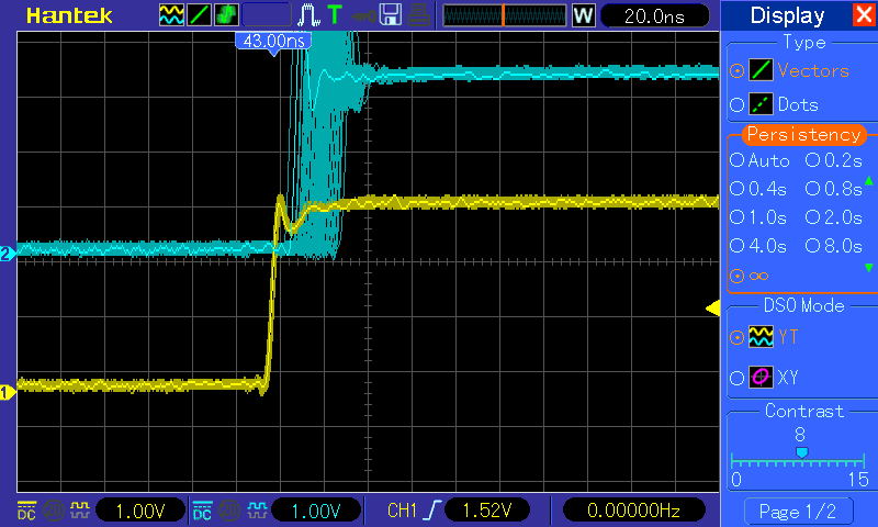
Figure 1: PPS: Oregano Master vs. PRU-ICSS Slave Port
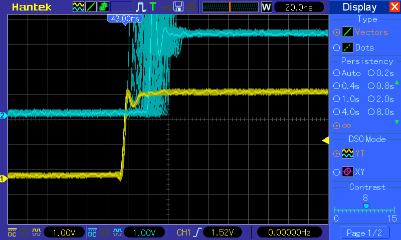
Figure 2: PPS: Oregano Master vs. GMAC Slave Port
4.3.6. PTP Boundary Clock
PTP boundary clock (BC) is supported on AM571x and AM572x IDKs. In the case of AM571x IDK, BC with two or three ports is supported. These two or three ports can be any combination of the three ports, i.e., GMAC port, one ICSS1 PRU port and one ICSS2 PRU port. In the case of AM572x IDK, BC with two ports, i.e., GMAC port and one ICSS2 PRU port, is supported.
4.3.6.1. Software Overview
There are four main components to the software together to provide the boundary clock functionality. These are, from low to high level, the ICSS PRU firmware, the related kernel ethernet drivers, the linuxptp ptp4l application and the linuxptp phc2sys application.
ICSS PRU Firmware
The ICSS PRU firmware used in BC is the PRP firmware (with PTP timestamping capability enabled) configured to run in Single Attached Node (SAN) mode.
CPSW/CPTS Ethernet Driver
This is the same CPSW/CPTS Ethernet driver implemented for GMAC PTP OC.
ICSS-PRU/IEP Ethernet Driver
This is the same ICSS PRU Ethernet driver implemented for PTP OC.
BC Internal Clock Sync Monitoring Driver
A thin PTP BC driver layer is added on top of the ICSS-PRU/IEP and CPSW/CPTS Ethernet drivers in order to support the BC internal clock synchronization. This thin layer of driver is responsible for keeping track of which internal clock has its PPS enabled and giving permission to the requests by the internal clocks to generate PPS. Keeping track of PPS enablement is necessary because, at any instance of time, at most one clock can enable its PPS. For otherwise the SoC may be permanently damaged.
Application linuxptp ptp4l
This is the application provides the BC PTP functionality. In the AM57xx BC, the linuxptp ptp4l program is configured to run in jbod (just a bunch of device) mode, i.e., the BC PTP clock is modelled on more than one internal clocks instead of one single clock.
Application linuxptp phc2sys
The linuxptp phc2sys is used to perform synchronization of the internal clocks of a BC in jbod mode. For AM57xx BC, the phc2sys is enhanced to support the synchronization of the BC internal clocks by reading the timestamps of the PPS generated by the internal master clock and captured by the internal slave clocks. phc2sys then feeds the timestamps into linuxptp’s servo algorithm. The algorithm then produces the needed clock adjustment, usually in ppb of the nominal clock frequency, which is then passed to the kernel driver for clock adjustment by calling Linux PTP subsystem’s standard API.
Internal Clock Synchronization
Although the PTP clock time in the PTP network of the BC appears coming from one clock source, the PTP clock time available on the AM57xx ethernet ports are actually generated by different clocks internally. In particular, the PTP clock time on the CPSW GMAC port is generated by the CPTS module, and the PTP clock time on the ICSS PRU ports is generated by the corresponding IEP module on the respective ICSS. Since these clocks are running on their own separately, thus some internal synchronization mechanism is needed in order to make the AM57xx BC internal clocks appear as one clock source in the PTP network.
The internal clock synchronization can be considered in two parts. The first part is the alignment of the clock time up to within one second. This can easily be done by just reading one internal clock’s time and write it to the other internal clock by application software alone under the assumption that the whole read and write operation takes less than one second. The other part of synchronization is to align the two clocks’ time to the second boundary.
In this AM57xx BC implementation, the alignment of two internal clocks’ time to the second boundary is done by using the PPS generated by one internal (master) clock latched into another internal (slave) clock. This means that the PPS received by an internal clock is timestamped. This timestamp is then consumed by a servo application in the calculation of the adjustment needed in order to align the internal slave clock’s second boundary to that of the internal master clock.
Here the internal master clock of the BC is the internal clock that is synchronized to a PTP master clock over the PTP network, i.e., the corresponding ethernet port is in PTP slave port state.
4.3.6.2. Hardware Overview
For AM57xx IDK BC, since PPC generated by one internal clock needs to be latched into another internal clock, hardware, mainly blue wire, modifications are needed in order to achieive the latching of the PPS generated by one internal clock into another internal clock.
Refer to the Hardware Modifications
4.3.6.3. Test Setup/Procedure
A Sample BC Setup
A sample set up for testing purpose is shown below.
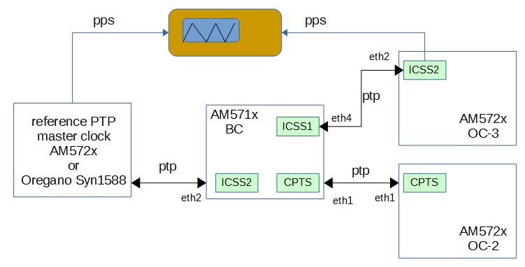
In this scenario, the BC ICSS2 PRU port (interface eth2) is in PTP slave state (ICSS2-IEP is the BC internal master clock). The other two ports, BC ICSS1 (interface eth4) and BC CPSW/CPTS (interface eth1) are in PTP master state (ICSS1-IEP and CPTS are the BC internal slave clocks).
Getting a PTP master clock ready
Start a reference PTP master clock that is connected in the PTP network as shown in the sample setup.
If the PTP master clock is an AM572x OC running linuxptp ptp4l, and for testing purpose, a line such as
clockClass 6
in the [global] section of the OC’s linuxptp configuration file can be helpful to make sure that the OC will be a master clock. Refer to PTP Ordinary Clock for starting an AM57xx OC.
Preparation on the AM57xx BC IDK
This section assumes that an AM571x is used. It should be similar for AM572x except that information about ICSS1 PRU (PRUSS1), eth4 and eth5 are not applicable.
Hardware
AM571x
Connect the following 6 pins together. See the AM571x Mod List for more details.
- timer16: C23 XREF CLK3
- timer15: AC10 (input): USB2_DRVVBUS (USB2_VBUS_EN)
- pr1_edc_sync0_out
- pr1_edc_latch0_out
- pr2_edc_sync0_out
- pr2_edc_latch0_out
Example: See below pictures (J21 is connector along top edge)
| Wire on AM571x IDK | signal |
|---|---|
| lower left yellow (above board) | timer15 |
| top right yellow (coming out from underneath) | timer16 CLK3 out |
| J21-18 left green | pr2_edc_latch0_out |
| J21-20 right green | pr1_edc_latch0_out |
| J21-54 left red | pr1_edc_sync0_out |
| J21-56 right red | pr2_edc_sync0_out |
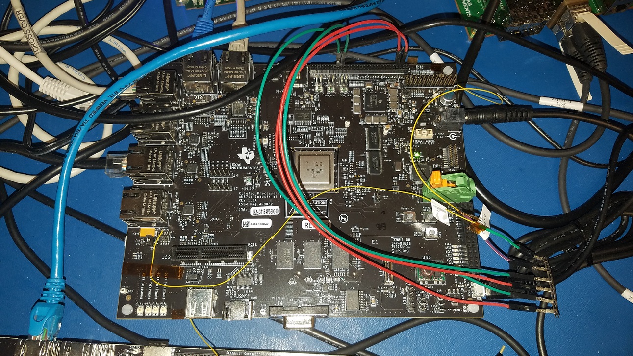
and this more J21 focused of the same picture above
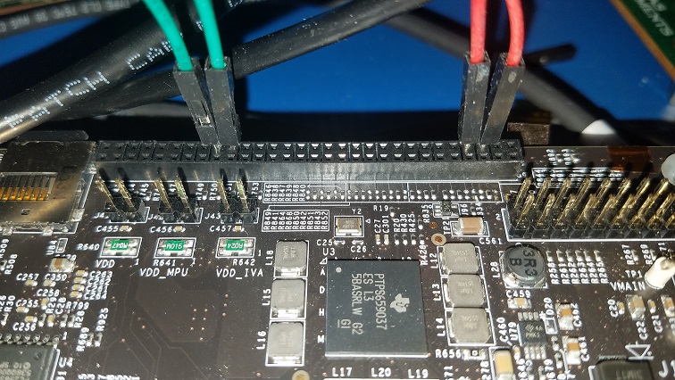
AM572x
Connect the following 4 pins together. See the AM572x Mod List for more details.
- timer16: C23 XREF CLK3
- timer15: AC10 (input): USB2_DRVVBUS (USB2_VBUS_EN)
- pr2_edc_sync0_out
- pr2_edc_latch0_out
Software
See a complete sample log for AM571x BC log here. As is shown in the log, right after the root login, the content of some shell scripts are displayed. Some of the scrits are for retrieving system information while others are for performing configurations. These sample scripts are for informational purpose only.
Since BC and OC are supported by using the PRP firmware configured to run in SAN mode, make sure to boot up the kernel with the parameters
- ti_prueth.pruss1_ethtype=2
- ti_prueth.pruss2_ethtype=2
in the bootargs. The firmware
- am57xx-pru0-pruprp-fw.elf
- am57xx-pru1-pruprp-fw.elf
will be loaded.
Make sure the following two lines appear in the start up log:
prueth pruss2_eth: TI PRU ethernet (type 2) driver initialized
prueth pruss1_eth: TI PRU ethernet (type 2) driver initialized
Once the AM57xx IDK is boot into kernel prompt, use command, for example,
$ ls /sys/devices/platform/pruss1_eth/net
  eth4/  eth5/
to see which interface is available on which ICSS. For GMAC port, use the command
$ ls /sys/devices/platform/44000000.ocp/48484000.ethernet/net
  eth0/ eth1/
Then enable SAN mode on each of the ICSS PRU interfaces (assuming eth2 and eth3 are on ICSS2, eth4 and eth5 are on ICSS1):
$ echo 1 > /sys/kernel/debug/prueth-eth2/prp_emac_mode
$ echo 1 > /sys/kernel/debug/prueth-eth3/prp_emac_mode
$ echo 1 > /sys/kernel/debug/prueth-eth4/prp_emac_mode
$ echo 1 > /sys/kernel/debug/prueth-eth5/prp_emac_mode
Next, configure each BC interface with a proper IP address. For example,
$ ifconfig eth1 192.168.1.1
$ ifconfig eth2 192.168.2.1
$ ifconfig eth4 192.168.4.1
Starting the BC applications
Make sure the linuxptp BC configuration file bc.cfg (included in zip file)
[global]
tx_timestamp_timeout 10
logMinPdelayReqInterval -3
logSyncInterval -3
twoStepFlag 1
summary_interval 0
[eth1]
boundary_clock_jbod 1
egressLatency 146
ingressLatency 346
[eth2]
boundary_clock_jbod 1
egressLatency 726
ingressLatency 186
[eth4]
boundary_clock_jbod 1
egressLatency 726
ingressLatency 186
is available in the filesystem. Start ptp4l in the background and with display log to stdout enabled:
$ ptp4l -2 -P -f bc.cfg -m &
Wait to see the PTP slave port clock is sync and stabilized, for example, seeing similar lines:
ptp4l[304.713]: rms    7 max   12 ( -12,    1) freq  -8253 +/-   4 delay     7 +/-   1
ptp4l[305.714]: rms    2 max    4 (  -4,    2) freq  -8248 +/-   3 delay     8 +/-   0
ptp4l[306.714]: rms    2 max    3 (  -3,    3) freq  -8248 +/-   3 delay     8 +/-   0
then start phc2sys to perform the BC internal clock sync in the background
$ phc2sys -a -X -g eth1 -m &
where the new options added in this implementation are
-X: use extts (pps) to perform BC internal clock synchronization.
-g: specify which interface is the GMAC port interface
Lines similar to the following should be displayed after a few seconds (mixed with the “ptp4l[304.713]: rms ...” lines from ptp4l) :
phc2sys[373.480]: eth4 phc offset       -14 s2 freq   -8311
phc2sys[373.500]: eth1 phc offset       -18 s2 freq   -8315
Start an AM57xx OC in slave only mode connected to a BC’s master port, for example, the AM572x OC-3 in the sample setup. To make sure the OC is started in slave only mode, the ptp4l command
$ ptp4l -2 -P -f oc.cfg -s -m
can be used. The slave OC’s PPS can then be measured against the reference PTP master clock’s PPS.
Forcing BC Port State Change (for Testing Purpose)
To force a port state change on the BC ports for testing purpose, one can bring down the current reference PTP master clock and bring up another reference PTP master clock connected to, for example, the BC’s eth1 interface in the sample setup. Or simply rearrange the cable connections in the sample setup as shown below.
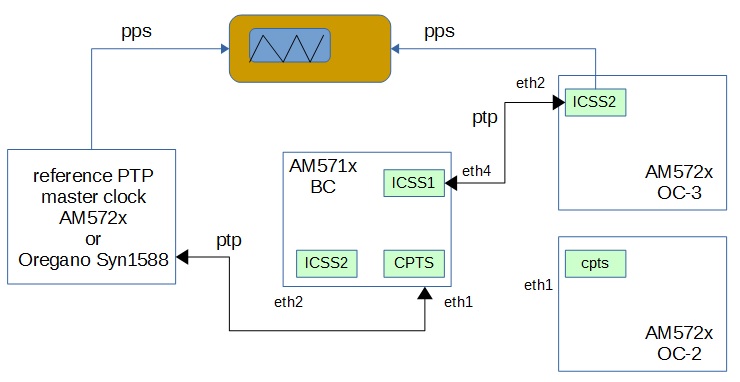
See here for a sample log when the BC’s cables are reconnected. The sample log starts right before when the cable is disconnected from eth2 on BC’s ICSS2 in the sample setup.
4.3.6.4. Test Results
BC (GMAC ICSS2)
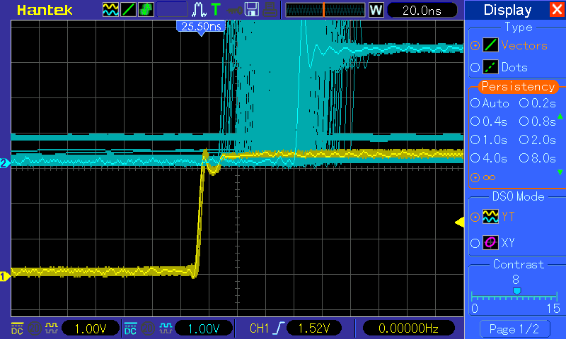
BC (GMAC ICSS1)
BC (ICSS2 GMAC)
BC (ICSS1 GMAC)
BC (ICSS2 ICSS1)
BC (ICSS1 ICSS2)
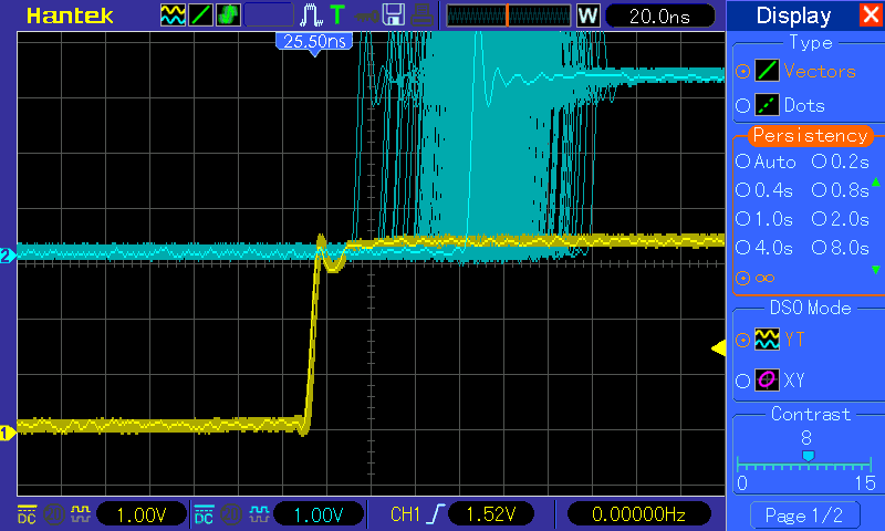
4.3.6.5. Limitations
- At most one port from each of the three modules, CPSW, ICSS1 and ICSS2, can be as a BC interface.
- In the current implementation, when running more than one OC, for example, ICSS1 OC and ICSS2 OC, only one pps can be enabled through command line. In this example, if ptp1 is the device for ICSS2 OC and ptp2 is the device for ICSS1 OC, then only one of the following will be allowed:
echo 1 > /sys/devices/platform/pruss2_eth/ptp/ptp1/pps_enable
or
echo 1 > /sys/devices/platform/pruss1_eth/ptp/ptp2/pps_enable
The same is true for other combinations. The intention is to avoid having more than one PPS enabled when the IDK has the HW mod mentioned in Hardware Modifications for AM57xx IDK BC and the pins are tied together.
4.3.7. PTP Roadmap
The following features are not yet supported as of Processor SDK 4.2 release, but will be added in future
Redundancy (HSR/PRP) Support in OC/BC
Transparent Clock
4.4. RSTP
This is a simple demonstration example to setup a RSTP network which is a mode of the mstpd daemon that is provided in the Processors Linux SDK file system. This example setup is done from the Linux command line. Users that require automatic interface, bridge and msptd daemon setup at system initialization will need to do the steps necessary to implement this initialization method.
https://wiki.linuxfoundation.org/networking/bridge
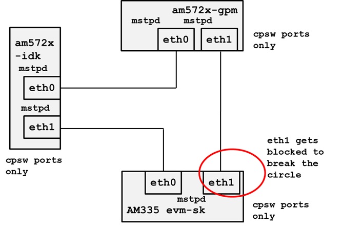
3 node ring demonstrating port blocking on low cost link
Please note that the topology was tested across CPSW only ports, PRU-ICSS Ethernet only ports and a one CPSW and one PRU-ICSS port.
Setup the ports, IP addresses are not used for the Ethernet ports in a bridge.
ifconfig eth1 up
brctl addif br0 eth0
brctl addif br0 eth1
ifconfig br0 up
4.5. CCLink
Overview
Control and Communication Link (CC-Link) is an open network administered as a fully-open architecture by the CC-Link Partner Association (CLPA). CC-Link is available in multiple formats: CC-Link, CC-Link Safety, CCLink IE (Industrial Ethernet) Control, and CC-Link IE Field. CC-Link IE Field Basic (or IEF Basic) is a new addition to the family of CC-Link IE open network technologies that enable device vendors to easily add CC-Link IE compatibility to any product with a 100-Mbit Ethernet port.
Supported TI Platforms
The table below lists the TI platforms which support CCLINK IEF Basic with EMAC, and PRU-ICSS, respectively.
Device EVM IEF Basic on EMAC IEF Basic on PRU-ICSS AM572x AM572x EVM X AM572x IDK X X AM571x AM571x IDK X X AM437x AM437x EVM X AM437x SK X AM437x IDK X X AM335x AM335x EVM X AM335x BeagleBoneBlack X AM335x SK X AM335x ICE X X K2G K2G EVM X K2G ICE X X |
Source Code for CCLINK IEF Basic
The CCLINK IEF basic source code for Linux can be requested from CLPA. It can also be retrieved from Processor SDK CCLink Source.
Compile CCLINK IEF Basic with Processor SDK Linux
Starting from Processor SDK Linux Releases 4.1.0, the pre-built binaries and configuration files for CCLINK IEF Basic will be part of the filesystem of Processor SDK Linux. The binaries (Master_sample and Slave_sample) can be located under the /usr/bin folder. The configuration files (MasterParameter.csv and SlaveParameter.csv) are placed at /usr/share/cclink.
If it is needed to rebuild the sources, the CCLINK IEF Basic sources can be fetched directly to the EVM and compiled natively on target. Using the source code at Processor SDK CCLink Source as the example:
- CCLINK IEF Basic for Master
First change directory to the Linux build folder for master, i.e., CCIEF-BASIC_Master/build/linux. Then, run “make” which generates Master_sample
- CCLINK IEF Basic for Slave
First change directory to the Linux build folder for slave, CCIEF-BASIC_Slave/build/linux. Then, run “make” which generates Slave_sample
An alternative to rebuild CCLINK IEF Basic is cross-compilation on X86 using the Yocto recipe. In order to do that, please refer to Processor SDK Building The SDK to set up the build environment, and Processor SDK Yocto Recipes to bitbake the recipes and install the newly built packages for CCLINK IEF Basic:
MACHINE=am57xx-evm bitbake ccief-basic
After the bitbake commands above are successfully done, the newly built ccief-basic binaries can found from the folder of ./build/arago-tmp-external-linaro-toolchain/work/armv7ahf-neon-linux-gnueabi/ccief-basic/<ver_number>/packages-split/ccief-basic/usr/bin.
Run CCLink IEF Basic Sample Application
The picture below shows the test setup for the CCLINK IEF basic master and slave applications running on the supported TI platforms. For both the master and the slave stations, connect the Ethernet ports to be tested to a switch.
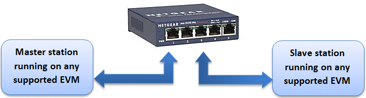
Please note that the jumper setting for AM335x ICE V2 EVM needs to be set correctly based on the type of application demonstrated:
- If running with EMAC, connect the jumper J18 and J19 for both boards into EMAC mode. Hence, connect pin1 and pin2.
- If running with PRU_ICSS, connect the jumper J18 and J19 for both boards into ICSS mode. Hence, connect pin2 and pin3.
Master Sample Application
Before running the master sample application, first obtain the IP address of the slave Ethernet port to be tested. Then, modify /usr/share/cclink/MasterParameter.csv to update “Slave1 IP address” using the IP address of the Slave station. After that, run the master sample application: “Master_sample /usr/share/cclink/MasterParameter.csv”
The figure below shows the sample output from the console of the master station.
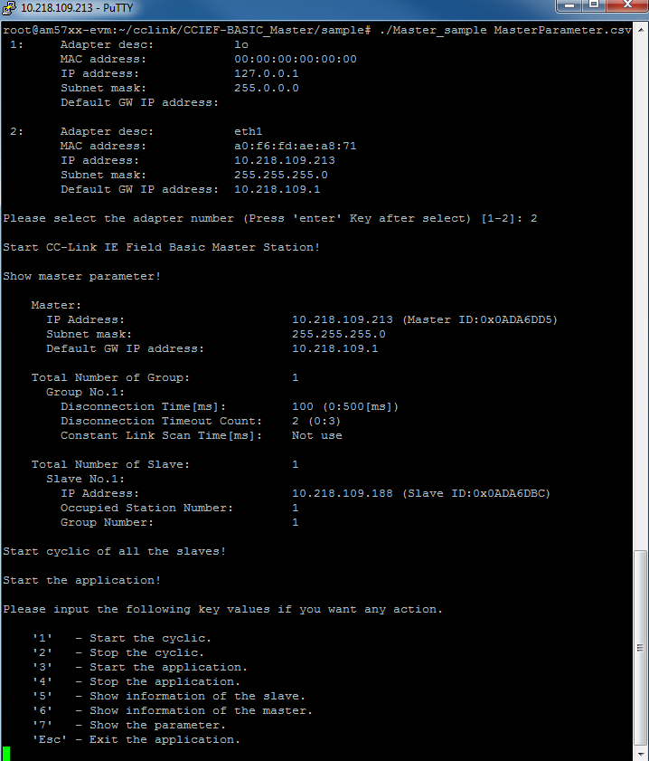
Slave Sample Application
On the slave station, simply run the slave sample application: “Slave_sample /usr/share/cclink/SlaveParameter.csv”
The figure below shows the sample output from the console of the slave station.
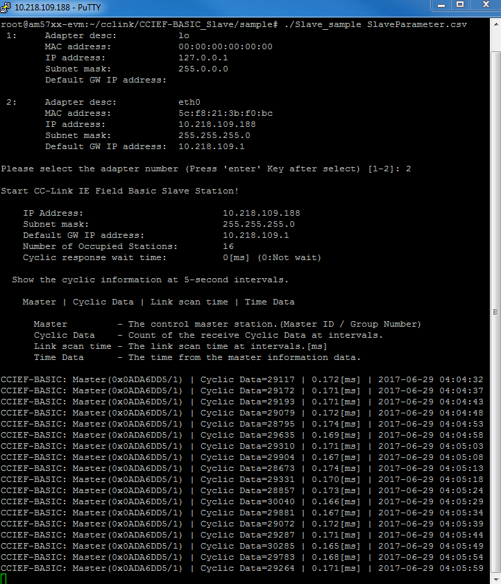
Compliance Testing
Every CCLINK IEF Basic application when demonstrated on any platform has to pass the conformance testing for various functionalities of IEF Basic. The conformance test results are sent to CLPA for approval. Upon approval from CLPA, the platform is accepted as CC-Link IEF Basic complaint.