3.1. PRU ICSS Industrial Drives User Guide
3.1.1. Introduction
PRU-ICSS Industrial Drives package is designed for the Sitara processor AM437x (with PRU-ICSS IP) to enable customers leverage Industrial Drives (position, current sense & control algorithm) capabilities
3.1.3. System Requirements
3.1.3.2. Component Version
The following is a list of tools bundled into the CCS installer. If you need to install CCS, see the CCS installation section
| Component | Version |
|---|---|
| CCS | 8.1.0 |
| Linaro GCC ARM Compiler | gcc-arm-none-eabi-6-2017-q1-update |
| Linaro GCC ARM Compiler (aarch64) | gcc-linaro-7.2.1-2017.11-i686-mingw32_aarch64-elf |
This release requires Processor SDK RTOS, see Processor SDK Getting Started Guide
| Component | Version |
|---|---|
| Processor SDK RTOS for AM437x | 5.1.0 |
Details on Processor SDK RTOS component versions can be found here
3.1.5. Directory Structure
|   |--- docs

|   |--- examples

|       |--- board

|           | --- common

|       |--- motor_control

|           | --- control

|               | --- foc

|               | --- math_blocks

|            |--- projects

|                   |--- ccsproject_args

|       |--- endat_diagnostic

|       |--- tamagawa_diagnostic

|       |--- hdsl_diagnostic

|   |--- interfaces

|       |--- include

|               |--- firmware

|                   |--- am437x

|       |--- endat_master

|               |--- doc

|               |--- driver

|               |--- firmware

|               |--- include

|               |--- projects

|                   |--- ccsproject_args

|       |--- pru_onchip_adc_sampling

|               |--- firmware

|       |--- sddf

|               |--- doc

|               |--- driver

|               |--- firmware

|               |--- include

|       |--- tamagawa_receiver

|               |--- doc

|               |--- firmware

|                   |--- include

|               |--- include

|               |--- projects

|                   |--- ccsproject_args

|       |--- hdsl_master

|               |--- doc

|               |--- firmware

|               |--- include

|               |--- projects

|                   |--- ccsproject_args

|       |--- tools

|           | --- bin2header
Note
Refer to install path to get updated view for any changes in directory structure
3.1.6. Generating Project files
Note
Unlike [legacy Industrial SDK], the CCS project files are not readily available in the protocol package installer. IA_SDK_HOME is no longer declared as a environmental variable. This is declared in projectCreate for each project. Remove any declaration of IA_SDK_HOME from the system environment before generating or building a project. The steps that are involved to generate CCS project files with the help of the Batch file or Shell script are as explained below.
3.1.6.1. Steps to generate Project files
- Open Command/Shell Prompt and navigate to
[INSTALL-DIR]/<interfaces | examples>/<interface name | example name>/projects- interface name can be endat_master, hdsl_master or tamagawa_receiver
- example name can be motor_control
- Run projectCreate.bat or projectCreate.sh
- Note:
#. Following variables used by script can be overridden at shell/command prompt (if all packages are installed in default directory, overriding is not required)
- CCS_INSTALL_DIR - Set the path where the recommended version of CCS is installed in user machine(The path upto where folder ‘eclipse’ is located.)
- CCS_WORKSPACE_LOC - Set the CCS workspace location. This folder will be created if it doesn’t exist already.
- IA_SDK_HOME - Specify the IA_SDK_HOME based on the the directory where the industrial package is installed.
- PDK_INSTALL_PATH - Set the path where PDK RTOS package is installed (Refer to default path in projectCreate.bat)
- PROJECT_CREATE_DIR - Set the folder where the created project will be kept. User can import the projects from this directory to CCS
- PROJECT_CREATE_OPTIONS_FILE_DIR - Specify the directory where the project create options files are kept. This folder contains the *.txt files which specify the project settings (linked files, predefined symbols, compiler and linker options for a specific project)
- Ensure that Code Composer Studio is not running when executing projectCreate.bat or projectCreate.sh
- If the project create is successful, the generated project files will
be found in
[INSTALL-DIR]/<interfaces | examples>/<interface name | example name>/projects/<project_name>_AM437x_arm
3.1.6.2. More info
The projectCreate.bat or.sh utilizes the project arguments provides in
[INSTALL-DIR]/<interfaces | examples>/<interface name | example name>/projects/ccsproject_args
to generate the project file
3.1.7. Applications
Following ones can be created using project file creation method mentioned in the above section
3.1.7.1. EnDat diagnostic
Project directory: [INSTALL-DIR]/interfaces/endat_master/projects
EnDat is a bidirectional interface for position encoders. During EnDat operation the EnDat master receives position information from the EnDat position encoder. The EnDat diagnostic application for SYS/BIOS demonstrates the EnDat master operation on the AM437x.
This application is controlled with a terminal interface using a serial over USB connection between the PC host and the EVM. Please connect a USB cable between the PC and the EVM. A serial terminal application (like teraterm/ hyperterminal/ minicom) is then run on the host. To configure, select the serial port corresponding to the port emulated over USB by the EVM. The host serial port should be configured to 115200 baud, no parity, 1 stop bit and no flow control. Connect EnDat encoder to on-board connector J10. EnDat encoder can be connected to on-board connector J10 (channel 0) or using additional transceiver circuitry to use channel 1 or 2 (see note)
The EnDat driver provides a defined set of API’s to expose EnDat master interface. The diagnostic invokes these API’s to initialize EnDat, configure the host trigger mode, select between concurrent multi channel or single channel configuration, select the channel (channels in the case of concurrent multi channel configuration) and run the firmware. Once these steps are executed, the driver waits for the EnDat to be initialized. It then sets clock frequency to 200KHz (as propagation delay is not yet compensated) and obtains the encoder details including serial number, position resolution etc, and displays on the console. Based on the whether encoder is 2.2 or 2.1 type, it sets clock to either 8MHz or 1MHz respectively. While configuring clock, propagation delay is taken care using the automatically estimated propagation delay (user can override it too). In the case of concurrent multi channel configuration, if propagation delay between various channels are different, that too is automatically taken care.
Once initial setup is over, the diagnostic provides the user with a self explanatory menu. Two types of menu options are presented. One type (1-14) will send an EnDat command as per EnDat 2.2 specification. The other type (100-108) allows the user to configure clock frequency, various timing parameters, simulate motor control loop using 2.1 command as well as 2.2 command with safety (redundant position information), switch to continuous clock mode and monitor raw data. Concurrent multi channel configuration can work simultaneously for up-to three encoders with identical part number, all variants of 2.2 position commands as well as the 2.1 position command is supported and an additional option (109) to configure wire delay (useful when propagation delay in each channel is different) is available. Application by default, handles wire delay as required, the menu option provides a way to override it.
After the user selects an EnDat command, the diagnostic asks for more details to frame the command and performs a basic sanity check on the user entered values. Then the EnDat API is invoked to process the command. The received EnDat is processed & validated using the defined API’s. The result is then presented to the user.
Firmware sources are available @”interfaces\endat_master\firmware”, while documentations @”interfaces\endat_master\doc”.
Note
To make channel 1 or/and 2 functional, additional transceiver circuitry required as in [1] (but this also makes SD boot non-functional on AM437x IDK) and R541 on AM437x IDK has to be removed.
3.1.7.2. Tamagawa diagnostic
Project directory: [INSTALL-DIR]/interfaces/tamagawa_receiver/projects
This application is controlled with a terminal interface using a serial over USB connection between the PC host and the EVM. Please connect a USB cable between the PC and the EVM. A serial terminal application (like teraterm/ hyperterminal/ minicom) is then run on the host. To configure, select the serial port corresponding to the port emulated over USB by the EVM. The host serial port should be configured to 115200 baud, no parity, 1 stop bit and no flow control.
Connect the Tamagawa encoder via RS485 transceiver to the AM437x IDK. The connections between AM437x IDK and RS485 logic signals are:
- J16-28 (AM437x SoC pin: SPI0_D1 as ICSS0 UART RXD) to RS485 receive
- J16-30 (AM437x SoC pin: SPI0_CS0 as ICSS0 UART TXD) to RS485 transmit
- J16-32 (AM437x SoC pin: MCASP0_AHCLKR as ICSS0 PRU0 GPO3) to RS485 transmit enable
It is necessary to provide 3.3V to the RS485 logic side. The receive transceiver is always kept enabled with bus side connected as in Tamagawa Specification.
The firmware running on ICSS0-PRU0 provides a defined interface (refer to the documentations mentioned below for additional details). The Tamagawa diagnostic application interacts with the firmware interface. The application configures pinmux, initializes ICSS0-PRU0, loads the PRU firmware & executes it. It then presents the user with menu options to select Data ID code (as defined by Tamagawa) to be sent to the encoder. The application collects the data entered by the user and configures the relevant interface. Then via the interface, the command is triggered. Once the command completion is indicated by the interface, the status of the transaction is checked. If the Status indicates success, the result is presented to the user.
The PRU Firmware is available as a CCS project, written in C. Sources @”interfaces\tamagawa_receiver\firmware”, while documentations @”interfaces\tamagawa_receiver\doc”.
3.1.7.3. Hiperface DSL diagnostic
Project directory: [INSTALL-DIR]/interfaces/hdsl_master/projects
This application is controlled with a terminal interface using a serial over USB connection between the PC host and the EVM. Please connect a USB cable between the PC and the EVM. A serial terminal application (like teraterm/ hyperterminal/ minicom) is then run on the host. To configure, select the serial port corresponding to the port emulated over USB by the EVM. The host serial port should be configured to 115200 baud, no parity, 1 stop bit and no flow control.
Connect the Hiperface DSL encoder to HDSL+/- signals available on header J7 or Sub-D15 connector Universal Digital Interface to Absolute Position Encoders Reference Design board
The firmware running on ICSS0-PRU0 provides a defined interface (refer to the documentations mentioned below for additional details). The HDSL diagnostic application interacts with the firmware interface. The application configures pinmux, configures ICSS clock to 225MHz, configure GPIO’s, initializes ICSS0-PRU0, ICSS0-IEP, EDMA, loads lookup table for encoding/decoding of Hiperface data, loads the initialization section of PRU firmware & executes it. Firmware is split to three sections, initialization, datalink & transport. Once initialization in firmware is over, transport section code overwrites initialization section code, Firmware in conjunction with EDMA handles this. At startup, the application displays details about encoder & status. It then presents the user with menu options, based on the option selected, application communicates with HDSL interface and the result is presented to the user.
Firmware sources are available @”interfaces\hdsl_master\firmware”, while documentations @”interfaces\hdsl_master\doc”.
Note
A daughter board along with adapter card is required as in [2] and R541 on AM437x IDK has to be removed (as Peripheral Interface channel 2 is used).
3.1.7.4. Motor Control
Project directory: [INSTALL-DIR]/examples/motor_control/projects
The Motor Control demo demonstrates a sensored 3 phase sensored Field Oriented Control (FOC) of a single Permanent Magnet Synchronous motor (PMSM) using the onchip AM437x ADCs (default) or sigma delta decimation filtering and optionally the EnDat 2.2 master interface and a EnDat encoder attached to the motor. The FOC algorithm provides smooth speed control, with high dynamic performance. Position feedback, Current sense as well as FOC algorithm execution are synchronized with the PWM signal. Though not used in the present application, there is an option to synchronize PWM with external signal by enabling the macro SYNC_ECAT_PWM (refer code enclosed by this macro for more details). This can be leveraged to synchronize PWM with Industrial Communication protocols like EtherCAT, providing a synchronized Single Chip Industrial Drive & Communication solution. Please note - The use of sigma delta filtering requires an additional modulator and interface card [an example is shown in https://www.ti.com/tool/TIDA-00209] with the ADC_SDDF macro defined in the project. The FOC algorithm transforms the 3 phase AC current measurements to d-q axis values allowing control of torque and flux. To run this application connect the USB port of the EVM to the host PC to enable a UART over USB connection between the EVM and host PC. A serial terminal application (like teraterm/ hyperterminal/ minicom) is then run on the host. To configure the terminal, select the serial port corresponding to the port emulated over USB by the EVM. The host serial port should be configured to 115200 baud, no parity, 1 stop bit and no flow control.
The Motor drive signals are provided by the IDK over the three terminals of J17. In the cases when no encoder is used or when an encoder is available and attached to the longer shaft of the motor, then the connections from the EVM to the motor are: The Red wire from the motor should be connected to J17-1. The Black wire from the motor should be connected to J17-2. The Yellow wire of the motor should be connected to J17-3. Alternatively, if the encoder is attached to the shorter shaft of the motor, then the connections from the EVM to the motor are: The Yellow wire of the motor should be connected to J17-1. The Black wire from the motor should be connected to J17-2. The Red wire from the motor should be connected to J17-3. The encoder should be to be connected to the onboard M12 connector J10.
If sigma delta decimation filtering is used, AM437x IDK J17-1,2 & 3 to be connected to negative of channel 1, 2 & 3 of modulator card respectively. Then connect the positive terminal of channel 1, 2 & 3 as J17-1, 2 & 3 and make the connections as mentioned in the above paragraph.
The Motor control application has been validated using a Permanent Magnet Motor (BLY171D-24V-4000, Anaheim Automation). This is coupled to an EnDat 2.2 encoder (ROQ 437, Heidenhain). The motor can be controlled via terminal console.
Upon pressing enter in the console, user will be asked to enter motor control variables. Simply pressing enter will bypass the setting of any one variable. This is helpful, especially when only one variable needs to be changed. The meaning of these variables will change slightly with each of the different build levels. The default build level is LEVEL4 (closed speed loop with EnDat position feedback). The Build level can be changed using BUILDLEVEL in foc.h and then rebuild the project.
In LEVEL4, controlling variables are lsw and speed. The default value of lsw is 0. For an open speed loop set lsw to 1. Set lsw to 2 for a closed speed loop. The motor, BLY171D-24V-4000, has a maximum speed of 4000 RPM. The desired speed can be expressed as an RPM value in the range of 0 to 4000. To reverse rotation, a negative value is entered. In LEVEL5, the controlling variables are lsw and angle. In this configuration, lsw = 0 (default) is the position control is turned off. To enable position control set lsw to 1 or 2. The desired position can be specified as an angle in the range 0-360 to control the position.
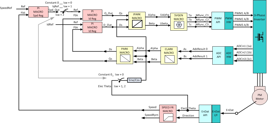
Figure : FOC Level 4
In LEVEL5, the controlling variables are lsw and angle. In this configuration, lsw = 0 (default) is the position control is turned off. To enable position control set lsw to 1 or 2. The desired position can be specified as an angle in the range 0-360 to control the position.

Figure : FOC Level 5
LEVEL6 is a combination of LEVEL4 & LEVEL5. In Level 6 the control variables are msw, lsw, speed and angle. When msw = 0 (default), the FOC is operating in speed control mode. In this mode, use the lsw and speed settings as discussed previously in LEVEL4. The angle input is not used in when msw = 0. To include position control set msw = 1. In this mode, the angle control operates as described in LEVEL5. In this configuration, the speed and lsw settings are ignored.
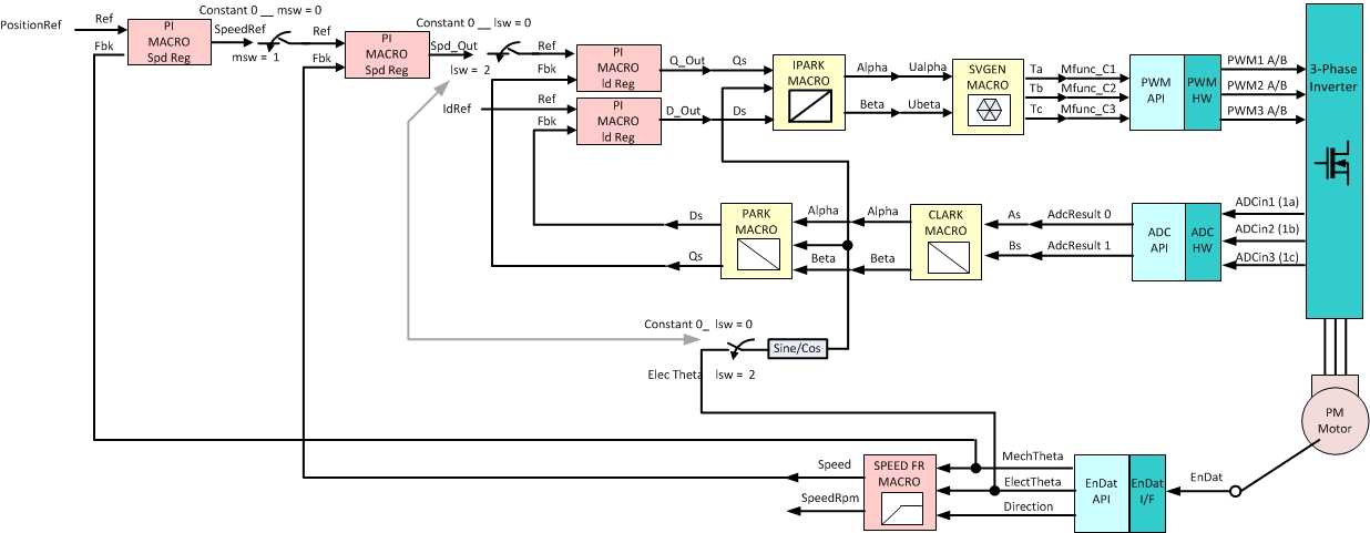
Figure : FOC Level 6
Note
NOTE 1 : Before proceeding with closed speed loop or position control ensure that encoder is connected and coupled to the motor and position offset compensation updated as mentioned below
NOTE 2 : It is recommended to bring motor to a standstill before connecting/disconnecting through JTAG
NOTE 3 : In LEVEL6, before switching from position control to speed control and viceversa, ensure that speed/position is set to zero (eg. before switching from speed control to position control mode, make speed as 0) and verify that the motor is at a standstill
NOTE 4 : Use a 24 V DC power supply with at least 1.67 A
3.1.7.4.1. ADC sampling firmware using ICSS0_PRU1
This firmware makes use of the PRU C compiler assembler and linker integrated in CCS6.x onwards. Additional detail on that is available is contained the following documentation.
PRU Optimizing C/C++ Compiler v2.0, https://www.ti.com/lit/ug/spruhv7/spruhv7.pdf PRU Assembly Language Tools v2.0 User’s Guide https://www.ti.com/lit/ug/spruhv6/spruhv6.pdf
sdk\interfaces\pru_onchip_adc_sampling\firmware has the example firmware implementation for ADC sampling and PWM & ADC synchronization
- icss_cfg_regs.hp: Register offsets for PRU_ICSS_CFG registers
- icss_cntl_regs.hp: Register offsets for PRU_ICSS_CTRL registers
- icss_ecap_regs.hp: Register offsets for PRU_ICSS_ECAP registers
- icss_event_defs.hp: PRU_ICSS system event defines
- icss_iep_regs.hp: Register offsets for PRU_ICSS_IEP registers
- icss_intc_regs.hp: Register offsets for PRU_ICSS_INTC registers
- icss_regs.hp: PRU_ICSS local memory map defines and Constant table entries
For more details on above, refer to AM437x TRM Chapter 30
- pru_adc_sampling_macros.hp: Reference macro implementations for legacy pasm CALL and RET instructions using clpru macros
- pru_adc_sampling.hp: Various configuration and register variable defines for ADC sampling firmware
- pru_adc_sampling.asm: Main assembly source file which implements ADC sampling and PWM to ADC synchronization using IEP timer module
- pru_adc_sampling.cmd: Command file for clpru linker (generates .out file from .obj files)
- pru_adc_hexpru.cmd: Command file for hexpru tool (generates .bin file from .out file)
- build_pru_adc_sampling.bat Bat file to build firmware C array header from assembly input files. Set PRU_C_COMPILER_PATH to PRU C compiler tool path
3.1.7.4.2. PRU ADC sampling firmware Host interface
Maintained in ICSS0 PRU1 Data memory (base address: 0x54442000)
- FOC_CONTROL_OFFSET(0x54442050): Indicate to PRU firmware when Host is ready for FOC processing 0: Wait 1: Continue
- FOC_TRIGGER_OFFSET(0x54442054): Select when to issue End of Conversion (EOC) to Host. On ADC EOC event (FOC_TRIGGER_IS_ADC) or on ADC EOC & EnDat EOC event (FOC_TRIGGER_IS_ENDAT). FOC_TRIGGER_IS_ADC is used today
- FOC_IEP_PWM_PERIOD_OFFSET(0x54442058): Configure the PWM_PERIOD for ICSS0 to track and synchronize the ADC events w.r.t PWM period (nano sec units)
- FOC_IEP_ADC_SOC_TRIGGER_OFFSET(0x5444205C): Configure ADC_SOC trigger time period from host (nano sec units)
- FOC_IEP_ENDAT_SOC_TRIGGER_OFFSET(0x54442060): Configure ENADT_SOC trigger time period from host (nano sec units)
- FOC_IEP_PWM_SYNC_OFFSET(0x54442064): Adjust IEP counter w.r.t PWM counter, program the IEP counter init value when PWM counter is cleared during synchronization phase (nano sec units)
3.1.7.4.3. PRU ADC sampling firmware overview
The Host will setup the PRU_ICSS INTC mapping, initialize PRU memories, initialize firmware configuration variables, download and start the firmware execution…
Init:
- Firmware clears all registers and wait for Host interface to be ready polling FOC_CONTROL_OFFSET
- When host CPU is ready, firmware initialize IEP CMP registers with
PWM_PERIOD, ADC_SOC_TRIGGER, IEP_PWM_SYNC values programmed by
host.
- PWM_PERIOD (CMP0) is 100000 (100us ) for 10 KHz
- ADC_SOC_TRIGGER (CMP1) is 50000 (50us) - mid point in PWM cycle
- IEP_PWM_SYNC is set to 50000 (50us)
- Clear all pending events for ADC, PWM, IEP and INTC
- Align PWM_TBCNT and IEP_COUNTER based on IEP_PWM_SYNC
Main loop:
- Firmware poll for IEP_CMP_HIT event, if match and ADC_SOC_TRIGGER (CMP1) then generate ADC_SOC via ICSS0_HOST5 > ICSS1_HOST0 >ADC1_EVT_TRIGGER connection
- Firmware poll for ADC_EOC event (from ADC register) if match then read samples from ADC FIFO, store to PRU data memory in required format and generate ADC_EOC to host cortex A9
3.1.7.4.4. Sigma Delta Decimation Filter
This is also integrated as a CCS project, PRU firmware sources are available @”interfaces\sddf\firmware”.
Sigma Delta is configured to triggered mode in motor control application using relevant API’s. In triggered mode, it is synced to PWM (SYNCOUT) and PWM SYNCOUT is configured to trigger at PWM count zero. Pre-triggering time from PWM reversal point is configured to half of three sample time for the default configurations (OSR128, 20MHz modulator clock). Three sample is the Sinc3 settling time and sampling around the PWM reversal instant to reduce harmonics in the current, hence pre-triggering with half the settling time. So trigger time from PWM SYNC is configured to (PWM period) / 2 - 1.5 * (sample time). Upon processing the third sample, PRU will trigger ARM interrupt and that will cause FOC loop to run.
Sigma Delta firmware also has capability to optionally generate an additional event synced to PWM, it is leveraged to make EnDat run in trigger mode.
For additional details please refer to the, firmware design, API guide as well as interface guide in “interfaces\sddf\doc” and Sigma Delta Decimation Filter GUI client example section
3.1.7.4.5. EnDat
This is integrated as a CCS project, PRU firmware sources are available @”interfaces\endat_master\firmware”
EnDat is configured initially to host trigger mode to extract details about the encoder. Once these details are obtained, it is switched to periodic mode and the command to be sent (2.2 position) periodically is setup. The triggering instant configured by ADC PRU ensures the completion of EnDat command by the time FOC interrupt occurs. During the execution of FOC interrupt, a lightweight EnDat API is invoked to read angular position for the already completed EnDat 2.2 position command.
Refer for more details, documentations @”interfaces\endat_master\doc”.
3.1.7.4.6. Field Oriented Control (FOC)
The Field Oriented Control (FOC) algorithm is used to control the motor. This implementation is derived from the C2000 PMSM sensored servo FOC.
The FOC implementation used in this application has 6 LEVEL’s.
Description of different LEVEL’s (all below are with closed current loop),
- LEVEL3 - open speed loop
- LEVEL4 - open speed loop, closed speed loop with EnDat feedback
- LEVEL5 - position control with EnDat feedback
- LEVEL6 - combination of LEVEL4 & LEVEL5 selection between it can be performed at runtime
3.1.7.4.6.1. Position Offset Compensation
The position value reported by encoder at zero electrical angle of the motor has to be set to zero. The position offset compensation value helps in correcting it. Position offset compensation between motor and encoder can have different values with a relative angular position between them. There are two methods to determine the poc as follows,
- A reliable, precise (and difficult) means to determine the poc is to incrementally change the position offset compensation and find the value at which q-axis value (at memory location 0x54442204) and the d-axis value (at memory location 0x54442104) current drawn is minimum. Note that FOC_SETUP macro has to be enabled for this.
- Position offset compensation quick estimate for a coupled motor and encoder set – Upon running the application at LEVEL4 (default), it will ask user to enter position offset compensation value, just enter will enable automatic estimation of position offset compensation. Application now waits for the user configuration to start the motor, start the motor in closed loop (lsw = 2). If motor runs satisfactorily, configure it to run at higher speeds. Upon trying to run at the next speed, application will report the automatically estimated position offset compensation value. Take note of the reported value at which motor runs satisfactorily at various speeds. Note that some times motor may go out of step or over current may happen, discard the values in those case.
Once the position offset compensation value is obtained, using either of the above methods, replace the following code in foc.c,
#if (BUILDLEVEL < LEVEL5)
_iq OffsetE = _IQ(0.0);
#else
_iq OffsetE = _IQ(-0.67);
#endif
Uint32 ElecThetaCalibrateFlag;
TO:
_iq OffsetE = _IQ(<new position offset compensation value>);
Uint32 ElecThetaCalibrateFlag = 1;
The above updates position offset compensation value to be used for LEVEL4, LEVEL5 & LEVEL6.
3.1.7.4.6.2. PI Tuning
The FOC algorithm uses several PI controllers. For a given setup, it may be necessary to tune the current, speed and position PI controller parameters. By enabling FOC_SETUP macro, these variables can be exposed through the PRU shared memory, which is modifiable at runtime using CCS. To change these values, first go to the CCS debug window. To enable the Non Debuggable Devices display, right click on AM437x_XDS100V2.ccxml [Code Composer Studio - Device Debugging] and select “Show all cores” . Then select Texas Instruments XDS100v2 USB Emulator_0/CS_DAP_DebugSS Connect using Non Debuggable Devices -> CS_DAP_DebugSS, add relevant variables to it (don’t forget to typecast it to float).
PI structure base address as follows (refer control/math_blocks/pi.h for more details),
d-axis current (id) - 0x54442100
q-axis current (iq) - 0x54442200
speed (spd) - 0x54442300
position (pos) - 0x54442400
The values that would have to be changed are:
Proportional gain (Kp) - 0xC
Integral gain (Ki) - 0x10
Maximum limit (Umax) - 0x14
Minimum limit (Umax) - 0x18
Eg., if you want to change Kp for speed PI, modify 0x5444230c (0x54442300 + 0xC)