Calibration
The calibration panel enables the user to calibrate the meter (using liner fit calibration) for different number of ranges. For example if an application requires higher accuracy for lower and higher flows, then 2 ranges may be used. This section covers the basic settings for calibration, and how to calibrate the meter manually or at run-time. Once the calibration is completed the meter constants can be transmitted to the target or output to a header file.
Calibration Configuration
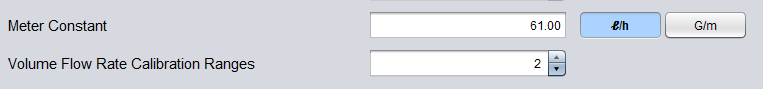
Fig. 21 Volume Flow Rate Calibration Ranges Configuration
Number of Calibration Ranges
The number of ranges used for calibration is configured in the Configuration->Parameter tab. Each time the number of ranges is updated, the project header files must be regenerated and the code must be recompiled for valid operation.
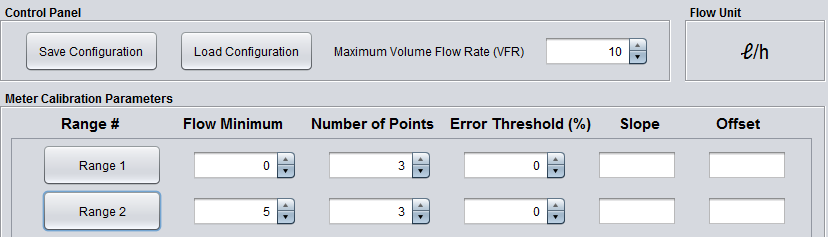
Fig. 22 Control Panel and Meter Calibration Parameters
The Control Panel at the top of the calibration tab includes the following options:
Saving Configurations
Save the current calibration configuration (values of each range) or load saved configurations by using the “Save Configuration” or “Load Configuration” buttons. The location of the configuration file will default to a USS directory created in your home folder upon installation, at ~home/USS_VERSION/USSWorkspace/USS_Project. Saving the configuration will also save the automatic logging state and location. Additionally, the GUI will automatically save the configuration upon exit and reload the exit configuration when launched.
Maximum Volume Flow Rate (VFR)
Input the Maximum Volume Flow Rate (VFR) based on the application requirements in the Control Panel.
Flow Unit
The “Flow Unit” is derived from the Meter Constant units in the Configuration->Parameter tab.
The “Meter Calibration Parameters” panel at the middle of the calibration tab includes the following options:
Flow Minimum
Input the “Flow Minimum” for each range. During run-time calibration, changing this value does not require the code to be recompiled.
Number of Points
Input the “Number of Points” for each range. Each calibration point is made up of an expected VFR and a mean VFR. During run-time calibration, changing this value do not require the code to be recompiled.
Error Threshold (%) (Optional)
Input the “Error Threshold” for each range. This value is used once calibration for a range is completed. For each calibration point, the mean VFR is applied with the meter constants. The calibrated mean VFR is compared versus the expected VFR and compared to this threshold. If the new calibrated value is above this threshold, the cell will be red, otherwise it will be green. During run-time calibration, changing this value do not require the code to be recompiled.
Slope
The slope is the meter constant calculated after all the calibration points have been entered.
Offset
The offset is the meter constant calculated after all the calibration points have been entered.
Manual Calibration
This section describes how to manually calibrate the meter. This requires to have log of previously tested data sets, including expected VFR and mean VFR.
- For each “Range #” in the Meter Calibration Parameters panel, click on the Range button.
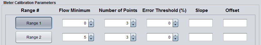
Fig. 23 Click on Range Button
- All of the Expected VFR and Mean VFR boxes will have a red edge around them.
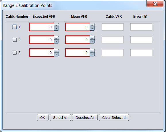
Fig. 24 Calibration Point Default
- Enter the Expected VFR and Mean VFR for each calibration point. As the values are updated the red edge will become green. Once all the calibration points are updated, the Calib. VFR and Error (%) columns will be populated.
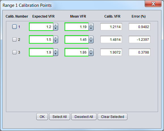
Fig. 25 Calibration Point Calibrated
- (Optional) Enter the Error Threshold for the calibrated Range. If the input “Error Threshold” is less than the absolute value of calculated Error (%) for each Calibration Point, the box will be red.
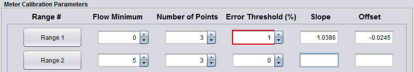
Fig. 26 Error Threshold Input
- To view which calibration point’s error was larger than the error threshold, click on the Range box.
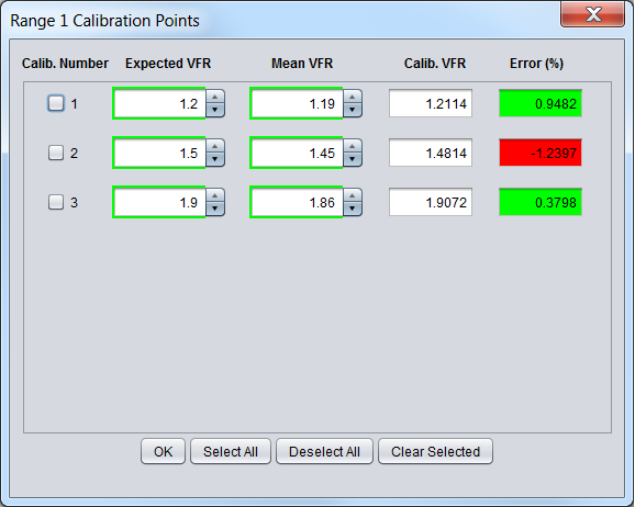
Fig. 27 Calibration Point Error
- The user can choose to re-calibrate the calibration point with larger error, or increase the Error Threshold for the corresponding range. If the Error Threshold is increased above the largest error then the Error Threshold’s red edge will become green.
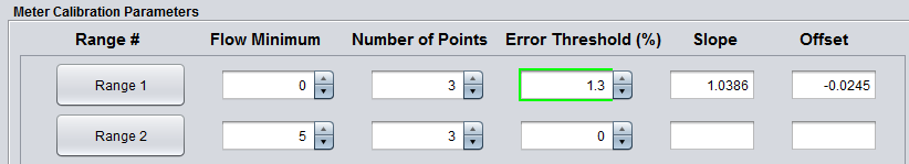
Fig. 28 Error Threshold Input Updated
- Repeat the previous steps for the remaining ranges. The slope and offset columns must have values populated when calibration is completed.
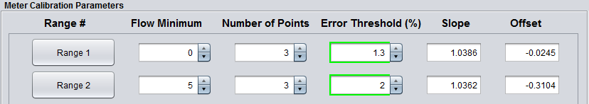
Fig. 29 Calibrated Ranges
- If the code running on the target was previously compiled using the # ranges used for manual calibration, then connect to the target and click the “Update Calibration” button, to store the meter constants. Otherwise, generate the header files and recompile the target code.
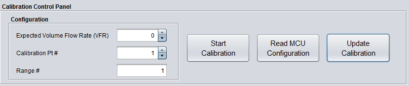
Fig. 30 Update Calibration
- A calibration update message should appear.
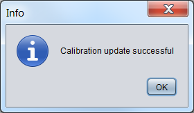
Fig. 31 Calibrated Ranges
- (optional) If Design Center is connected to a target board, click on “Read MCU Configuration” to view the meter constants stored in the target. This will send a request to the target to send the meter constants it has for each range. It will not overwrite the meter constants in the Meter Calibration Parameter panel.
Run-Time Calibration
This section describes how to calibrate the meter at run-time, instead of loading previously tested data sets.
- Enter the “Expected Volume Flow Rate (VFR)” and “Calibration Pt# ” in the Configuration panel. The Range text box will be updated automatically based on the “Expected Volume Flow Rate (VFR)” and will display the corresponding Range #.
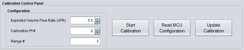
Fig. 32 Expected Volume Flow Rate Input
- Click the “Start Calibration” button on the Calibration Control Panel at the bottom of the Calibration Tab. The Start button notifies the target via HID command to initiate data transfer.
- Wait for a desired amount of time while captures are being averaged.
- Click the “Stop Calibration” button on the Calibration Control Panel at the bottom of the Calibration Tab. The Stop button notifies the target via HID command to stop data transfer.
- When the stop button is pressed the Calibration Pt in the corresponding Range # will be updated with the expected and mean VFR.
- This process must be repeated for all the Calibration Points in each Range. The slope and offset columns in the “Meter Calibration Parameters” will have the calibration constants when the calibration is completed.
- If the code running on the target was previously compiled using the # ranges used for run-time calibration. Then click the “Update Calibration” button, to store the meter constants. Otherwise, generate the header files and recompile the target code.
- (optional) Click on “Read MCU Configuration” to view the meter constants stored in the target. This will send a request to the target to send the meter constants it has for each range. It will not overwrite the meter constants in the Meter Calibration Parameter panel.
More Information
- For more information on the application, and available evaluation kits, see the download page.
- For technical support, email the USS GUI support team or visit the MSP430 E2E forum