RX Sniff Mode
Note: This panel is only available for the CC112x family of RF devices.
The RX Sniff Mode panel can be used to retrieve and verify the register settings to obtain the lowest possible average RX current consumption with a given application requirements. Further details about the “RX Sniff mode” feature can be found in the user guide for CC112x.
This document will only describe the user interface of this panel.
Transmit Parameters
The average power consumption depends on data rate and the preamble length. The parameters is used to calculate the timing of the RX duty cycling. The values given in this panel must be used by the transmitter to enable the receiver to successfully receive all packets without any loss.
The Symbol rate will be changed depending on the selected typical settings or the value given in the RF parameter panel.
The Preamble length can be changed but a initial value is set when a typical setting is selected. The given value is validated and an error message will be given if invalid. If the transmitter is controlled by SmartRF Studio, the preamble length must be set in the register PREAMBLE_CFG1::num_preamble . In order to achieve no packet loss the preamble length configuration in the sniff mode panel must match number of preamble bytes sent by the transmitter. Maximum preamble that can be set using the packet engine is 30bytes ( num_preamble ). To generate a longer preamble, one can disable the sync word, use fixed packet length, disable CRC and fill up the FIFO with preamble bytes. This enables another 128 bytes. For even longer preambles one can strobe TX with an empty FIFO. The chip will then send preamble until data is entered into the FIFO.
Signal Detection
For signal detection in RX Sniff mode there are two methods to determine if we have a valid signal or not. If the condition is not met within the calculated RX time, RX will terminate.
The RSSI method measure the input signal level and compare with the configured Carrier sense threshold value to determine if there is a carrier or not. If the signal is below the given threshold, RX will terminate. The RSSI method is faster than the “preamble” method and the average power consumption will be lower.
The Preamble (also called PQT) method is more robust than the “RSSI” method but takes a bit more time and therefore increase the power consumption. For settings with “zero” IF frequency, the “Preamble” method will not be available. The Preamble option will be disabled.
Timing Calculations
The timing calculations for both the preamble (PQT) and RSSI termination method is based on worst case scenarios of where in the cycle the sender starts sending preamble. The Event0 time (Or total cycle time. See also User Guide) must be short enough to be able to detect preamble/RSSI independent of when the transmitter start sending. The worst case scenario will be if the transmitter start sending preamble just before the receiver goes from RX to sleep. The preamble must then be detected the next time the receiver is in RX. The Event 0 time must therefore be set shorter than the preamble length with sufficient margin.
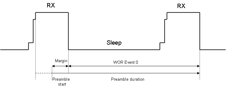
The illustration above shows that a longer preamble or a shorter WOR Event 0 time results in a larger margin. A larger margin gives more robustness and less chance of loosing packets. For best robustness the margin should be equal to the RX time (trx). This will result in WOR Event 0 time (total cycle time) is equal to preamble time subtracted with trx.
Average Current Consumption Calculations
The average current consumption is calculated for the RX duty cycle based on no packets are received. When a signal and a valid sync word is detected, the device will stay in RX until the complete packet is received. Therefore when packets are received the average current consumption increase.
The calculated value for average current consumption (when no packets received) is an estimate based on the following formula:

Timing values used in calculations:
| Value | Description |
| txtal | Startup time for crystal oscillator. This time is dependent on whether the crystal oscillator is kept on during sleep or not. For high data rate typical settings where the crystal oscillator is kept running a time equal to 4 * 32 KHz periods (RC oscillator periods) is used in calculations. For low data rate settings a time equal to 16 * 32 KHz periods is used in calculations. |
| tpll | Time for PLL. This time is set constant to 166 us in calculations. |
| trx | Time in RX. This time is calculated and will be dependent on typical setting and whether RSSI or PQT method is used. |
| tsleep | Time in sleep.This time is calculated and will be dependent on typical setting and whether RSSI or PQT method is used. |
The sum of (tpll + txtal) is called twakeup in the graph.
Current values used in calculations:
| Value | Description |
| ixtal | Current in crystal oscillator startup phase. This value is set to 2 mA in the calculations. |
| ipll | Current in PLL phase. This value is set to 18 mA in the calculations. |
| irx | Current in RX. This value is set to 21 mA in the calculations. The real value may vary depending on among other factors the input level of the received signal. |
| isleep | Current in sleep mode. The value 1 uA is used for the calculations. |
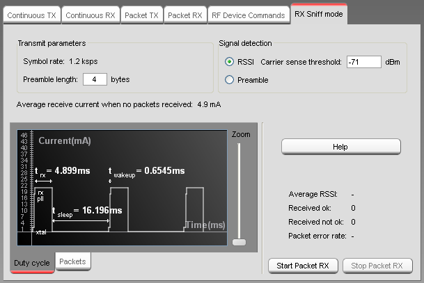
Duty Cycle
A graphical representation of the RX duty cycle is used to visually show the timings calculated by SmartRF Studio. The calculation is partly based on measurements and theoretical formulas. The calculated duty cycle and resulting sleep time is based on worst case scenarios for when transmitter starts sending preamble.
The duty cycle will indicate the current consumption and timing to start up the crystal oscillator ( xtal ) and the settling time for the pll . For the typical settings with low symbol rate (1.2 ksps and 9.6 ksps settings), the crystal oscillator is powered down when the device is in sleep to save power. For typical settings with higher symbol rates the crystal oscillator is kept on to allow for faster wakeup.
The rx , sleep and wakeup time is shown with the calculated values.
A zoom handle is provided to change the resolution in horizontal direction
If the sleep time is above a certain limit, the graphical representation will be compressed in order to show several rx periods. The compression is indicated with a “zig-zag” line. The RX sleep time will still be adjusted correctly.
Packet View
To verify that packet RX is working as expected with the given settings, it is possible to Start packet RX and to watch the contents of the packets by selecting the Packets tab. Packet Error Rate (PER) will be given on the right side in the same way as for the normal Packet RX function. The Packet RX function is configured to receive a infinite number of packets and the two first bytes of the payload will be read as the sequence number.
Invalid Parameters
If the given parameters give an invalid configuration of the RX Sniff mode, an error message will be given and the graphical duty cycle will be red. The previous register settings and the graph will be unchanged unitl valid values are given.