Developing with IAR
Installing IAR
The IAR toolchain contains many features beyond the scope of this document. More information and documentation can be found at IAR.com.
Check the BLE5-Stack 1.00.00 release notes to see which IAR version to use and any required workarounds. Object code produced by IAR may differ in size and performance as compared to CCS produced object code.
The following procedure describes installing and configuring the correct version of IAR and the necessary tools.
Install IAR Embedded Workbench for ARM
Download and install IAR EW ARM
To get IAR, choose one of the following methods:
- Download the IAR Embedded Workbench 30-Day Evaluation Edition – This version of IAR is free, has full functionality, and includes all of the standard features. The size-limited Kickstart evaluation option is not compatible with this SDK.
- Purchase the full-featured version of IAR Embedded Workbench – For complete BLE application development using the CC2640R2F, TI recommends purchasing the complete version of IAR without any restrictions. You can find the information on purchasing the complete version of IAR.
Attention
The version required is stated in the release notes. Opening IAR project files with a previous version of IAR may cause project file corruption.
Show Build Messages
TI recommends showing all the build output messages for full verbosity during building. To do this, go to Tools -> Options and set Show Build Messages to All (see Figure 16.)
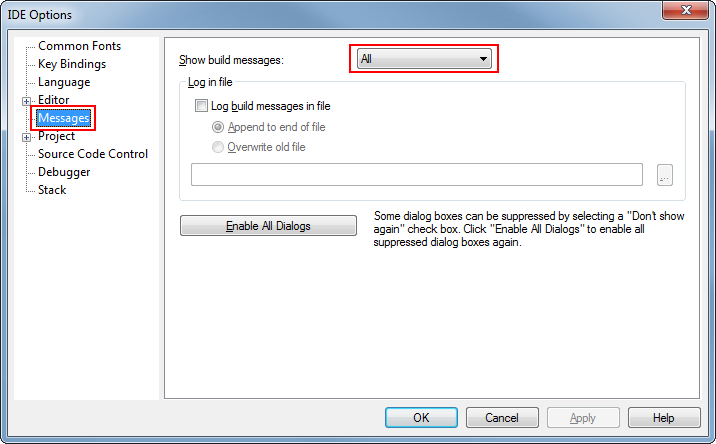
Figure 16. Show All Build Messages in IAR
Opening IAR Projects
Note
TI-RTOS driver and kernel examples are imported for IAR rather than supplied as pre-configured IAR workspace files. Instructions on how to create these projects are found here: Creating TI-RTOS (driver/kernel) Applications in IAR Embedded Workbench
This section describes how to open and build an existing project and references the simple_peripheral project. All of the BLE5-Stack projects included in the development kit have a similar structure.
Open the IAR Embedded Workbench IDE from the Start Menu.
Open an IAR workspace project: File -> Open -> Workspace...
- For this example, select <SDK_INSTALL_DIR>\examples\rtos\CC2640R2_LAUNCHXL\ble5stack\simple_peripheral\tirtos\iar\ble5_simple_peripheral.eww
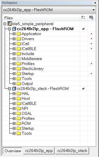
Figure 17. IAR Workspace Pane
This workspace file is for the simple_peripheral project. When selected, the files associated with the workspace become visible in the Workspace pane on the left side of the screen. See Figure 17.
Select either project as the active project by clicking the respective tab at the bottom of the workspace pane. In Figure 17., the Overview tab is selected. This tab displays the file structure for both projects simultaneously. In this case, use the drop-down menu at the top of the workspace pane to select the active project. Each of these projects produces a separate downloadable object. The simple_peripheral sample project is the primary reference target for the description of a generic application in this guide. The simple_peripheral project implements a basic BLE5-Stack peripheral device including a GATT server with GATT services. This project can be a framework for developing peripheral-role applications.
BLE5-Stack IAR project build configurations
This and all BLE5-Stack project workspaces contain various projects and build configurations as shown in Table 7. *_StackLibrary build configurations build the stack as a library as described in Stack Library Configuration (_stack_library).
| Project type | Project’s build configuration | Compatible project complement |
|---|---|---|
| Application | FlashROM | Stack - FlashROM |
| FlashROM_StackLibrary | Stack - FlashROM_StackLibrary | |
| FlashROM_StackLibrary_RCOSC | Stack - FlashROM_StackLibrary | |
| FlashROM_OAD_ImgB | Stack - FlashROM | |
| FlashROM_OAD_Offchip | Stack - FlashROM | |
| Stack | FlashROM_Library | Application - FlashROM_Library |
| FlashROM | Application - FlashROM |
Compile and Download
For all build configurations, the stack project should always be built before the application project.
For projects where the stack is built as a library:
Build the stack library project.
- Select the stack project.
- Select Project -> Make to build the stack.
Build the application project.
- Select the application project.
- Select Project -> Make to build the application.
Load the whole application
- To download and debug: Select Project -> Download and Debug
- To download without debugging: Select Project -> Download -> Download Active Application
Note
Application project that consume the stack in a library form will not have hard defined image boundaries.
After the initial build, if the stack project is not modified, only the application project needs to be rebuilt.
For projects where the stack and application are split images (not a library):
Build the stack project.
- Select the stack project.
- Select Project -> Make to build the stack.
Build the application project.
- Select the application project.
- Select Project -> Make to build the application.
Load the stack project.
- Select Project -> Download -> Download Active Application to download the stack project.
Load the application project.
- To download and debug: Select Project -> Download and Debug
- To download without debugging: Select Project -> Download -> Download Active Application
Note
The stack project defines the flash and RAM boundary parameters used by the application project. Any modifications to the stack project require a rebuild of the stack project, followed by a rebuild of the application project to use the new boundary settings. See Frontier Tool Operation.
After the initial build, if the stack project is not modified, only the application project needs to be rebuilt.
When the application is downloaded (that is, flash memory programmed), you can debug without reflashing the device. Go to Project -> Debug without Downloading.
Caution
Do not modify the CPU Variant in the project settings. All sample projects are configured with a CPU type, and changing this setting (that is, from CC2640R2F) may result in build errors.
Sample applications that implement the Over the Air Download (OAD) firmware update capability require the Boot Image Manager (BIM) project to be built. Refer to the Over the Air Download (OAD) section for more details.
Accessing Preprocessor Symbols
Various C preprocessor symbols may need to be set or adjusted at the project level. The following procedure describes how to access and modify preprocessor symbols.
- Open the Project’s Options and select the C/C++ Compiler Category.
- Open the Preprocessor tab.
- View the Defined symbols box (see Figure 18.).
- Add or edit the preprocessor symbols.
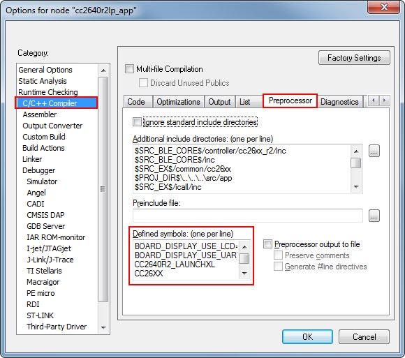
Figure 18. IAR Defined Symbols Box
Accessing Linker Symbols
Linker symbols may need to be set or adjusted at the project level in order to control the memory layout of the generated image. The following procedure describes how to access and modify linker symbols.
- Open the Project’s Options and select the Linker Category.
- Open the Config tab.
- View the Configuration File symbol definitions box (see Figure 19.).
- Add or edit the preprocessor symbols.
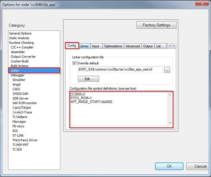
Figure 19. IAR Defined Symbols Box
Resetting the CC2640R2F in IAR
Select the Board Reset option from the following Reset (back arrow) Debug Menu drop-down box.
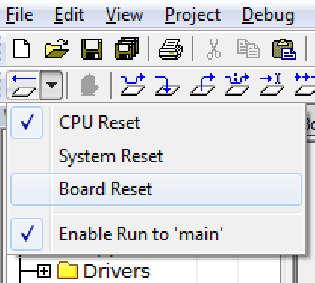
Figure 20. IAR Board Reset