Introduction
==================================
This example explains how to include and use the IR Generation driver.
Prerequisites
==================================
Software
---------
* CCS 6.1.3 or later
* TI-RTOS 2.20.01.08 or later
Hardware
---------
* 1x CC2650 Launchpad
Getting started
==================================
Making sure it works
---------------------------------
Ensure that the board is connected to the PC.
Open Code Composer Studio and import the project.
* Open Resource Explorer by going to View → Resource Explorer Classic
* Open up SimpleLink Academy → TI-RTOS → Projects
* Select `TI-RTOS IR Generation` for the platform you are using.
* Press the import button on the right side
To test that the software and hardware pre-requisites are fulfilled we are going to try to build and debug the project before going to the first task.
* Our first mission is to build the imported project. Select the project in Project Explorer and choose Project → Build All from the menu.
* When the project is built, we are going to make sure that the hardware and debugger work. To start debugging, press Run → Debug, or press F11.
* When the download is finished, press F8 or the green play button to run.
* After a few seconds you should see LED1 toggling on and off every second.
If you see LED1 blink then everything works and you may continue with the example.
[[y On Building
Note that the first time you build the project the whole TI-RTOS kernel will also be built. This may take several minutes, but is only done the first time. Subsequent builds will re-use the compiled kernel unless a configuration change is done.
]]
Orienting ourselves in the code
---------------------------------
The IR generation example comes preconfigured with two TI-RTOS `Task`s already constructed in `main()`. First task is set up to use the `workTaskFunc` function as the task function, which in turn uses the PIN Driver to toggle a led. The second task is set up to use the 'pinTaskFunc' function as the task function. The second task is used to handle button detection, including [debounce]{Debounce refers to the effect which typically happens to button presses. A button press is usually not a perfect edge, but may produce a rippled signal. It is possible to read an IO as not pressed, even though it is pressed. This is because of the ripple. As the button transitions from VDD to GND it may logically change value several times after the interrupt is generated. In order to make sure we read the IO when it has stabilized we wait 25ms. How long one needs to wait depends on the type of button used.}.
The tasks are created with the `Task_construct` in the main function. The main function also initializes the hardware.
In the `main()` function, after `BIOS_start()` is called, the main function will not progress further, but instead give control to the TI-RTOS scheduler which will call the `Task functions` of the tasks that are constructed. For example `workTaskFunc`. Normally, task functions will enter an infinite loop and never return, letting TI-RTOS switch to higher priority tasks or temporarily suspend the current task.
[[b! Training solution
The solution to these exercises found in this training are contained within the example's `solution` directory. You can simply copy and pasted the contents of the solution into their associated files and enable the build of the IR generation driver.
]]
Task 0 - Integrate IR generation driver
==================================
We will include the IR generation for a basic signal, in the 'pinTaskFunc'. This task is given higher priority than the 'workTaskFunc'. IR generation is somewhat timing critical and this is why it should be processed by a task with higher priority than some other task which does not perform timing critical processing.
Add support in board files
----------------------------------
The IR generation driver is written as RTOS driver, but it is not an official driver. So, there is no default support in any of the board files.
Add the following to the `CC2650_LAUNCHXL.c` file
```c
/*
* ============================= IRGEN begin ===================================
*/
#ifdef TI_DRIVERS_IRGEN_INCLUDED
#include "IRGENCC26XX.h"
IRGENCC26XX_Object irgenCC26XXObject = {0};
const IRGENCC26XX_HWAttrs irgenCC26XXHWAttrs = {
.irLedPin = Board_LED_IR,
#ifdef IRGENCC26XX_DEBUG
.irOutputPin = Board_IR_OUTPUT_DEBUG,
.irDataChPin = Board_IR_DATA_CH_DEBUG,
.irShadowChPin = Board_IR_SHADOW_CH_DEBUG,
#endif //IRGENCC26XX_DEBUG
.dmaChannelBitMask = (( 1 << UDMA_CHAN_TIMER0_A) | ( 1 << UDMA_CHAN_TIMER0_B) | ( 1 << UDMA_CHAN_TIMER1_A) | \
( 1 << UDMA_CHAN_SW_EVT0 ) | ( 1 << UDMA_CHAN_SW_EVT1 ) | ( 1 << UDMA_CHAN_SW_EVT2 ) | \
( 1 << UDMA_CHAN_SW_EVT3 )),
.dmaSoftChannelBitMask = (( 1 << UDMA_CHAN_SW_EVT0 ) | ( 1 << UDMA_CHAN_SW_EVT1 ) | \
( 1 << UDMA_CHAN_SW_EVT2 ) | ( 1 << UDMA_CHAN_SW_EVT3 )),
};
/* IRGEN configuration structure */
const IRGENCC26XX_Config IRGENCC26XX_config = {
&irgenCC26XXObject,
&irgenCC26XXHWAttrs
};
#endif //TI_DRIVERS_IRGEN_INCLUDED
/*
* ============================= IRGEN end ===================================
*/
``` Updates to `CC2650_LAUNCHXL.c`
There are some defines we need in the board header file, so add the following to the `CC2650_LAUNCHXL.h` file
```c
/* IR Engine IOs*/
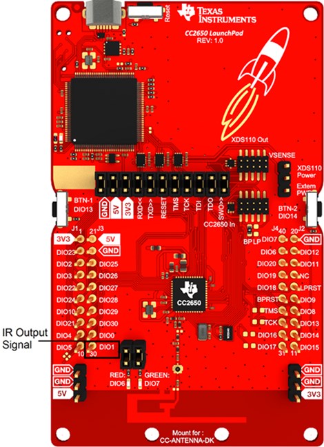
#define Board_LED_IR IOID_1
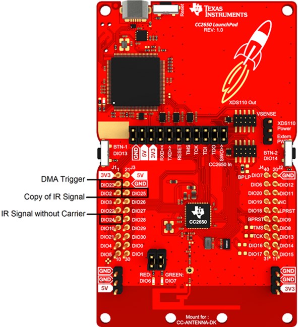
#define Board_IR_OUTPUT_DEBUG IOID_25 // DP0
#define Board_IR_DATA_CH_DEBUG IOID_24 // DP1
#define Board_IR_SHADOW_CH_DEBUG IOID_23 // DP2
``` Updates to `CC2650_LAUNCHXL.h`
As you can see we are adding 4 IOs. We will come back to the `_DEBUG` ones later. The IR generation driver assumes that these IOs are initialized. In order to make sure of this we add the IOs to the `BoardGpioInitTable`.
```c
Board_LED_IR | PIN_GPIO_OUTPUT_EN | PIN_GPIO_LOW | PIN_PUSHPULL | PIN_DRVSTR_MAX, /* IR signal initially low */
#ifdef IRGENCC26XX_DEBUG
Board_IR_OUTPUT_DEBUG | PIN_GPIO_OUTPUT_EN | PIN_GPIO_LOW | PIN_PUSHPULL | PIN_DRVSTR_MAX, /* IR debug signal initially low */
Board_IR_DATA_CH_DEBUG | PIN_GPIO_OUTPUT_EN | PIN_GPIO_LOW | PIN_PUSHPULL | PIN_DRVSTR_MAX, /* IR debug signal initially low */
Board_IR_SHADOW_CH_DEBUG | PIN_GPIO_OUTPUT_EN | PIN_GPIO_LOW | PIN_PUSHPULL | PIN_DRVSTR_MAX, /* IR debug signal initially low */
#endif //IRGENCC26XX_DEBUG
``` Adding IR generation IOs to `BoardGpioInitTable` in `CC2650_LAUNCHXL.c`
For simplicity we will enable IR generation driver by default when this board file is used. Note that the same define could be set in project options, if it should only apply to the specific project.
Add the following to the `CC2650_LAUNCHXL.h` file
```c
/* Enable/Disable IR */
#define TI_DRIVERS_IRGEN_INCLUDED
``` Updates to `CC2650_LAUNCHXL.h`
Integrate driver into source
----------------------------------
The next steps involve adding the following into ```irgeneration-main.c```.
We need to add the header so that we have access to the IR generation functions.
```c
/* Add IRGEN support */
#include "IRGENCC26XX.h"
``` IRGEN header
Then we need to define the handle for the IRGEN driver.
```c
/* IR generation handle */
static IRGENCC26XX_Handle irgenHandle;
``` IR generation handle
We also need to declare the callback function which the IRGEN driver will use.
```c
/* IR generation callback */
static void IRGENCC26XX_callbackFxn(IRGENCC26XX_Handle handle, bool done);
``` IR generation callback
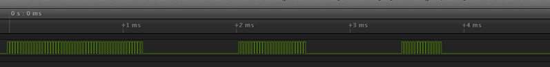
Next we will define a sample signal. This is the input to the IRGEN driver. Normally this would be read from a database, or calculated from a formula. There are two arrays. One array defines the [Mark period and the other defines the Space period]{An IR signal is often described in terms of marks and spaces. Mark denotes the active part of a pulse, whereas Space denotes the inactive part of a pulse. A pulse is a pair of Mark and Space, and active means that the IR diode is actively driven. The Mark period is often modulated with a carrier, but it is not always the case.}.
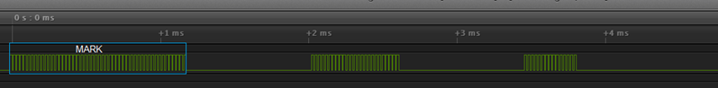
[[+g IR signal, Marks and Spaces?
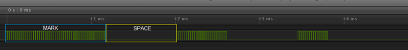
An IR signal is often described in terms of marks and spaces. Mark denotes the active part of a pulse, whereas Space denotes the inactive part of a pulse. A pulse is a pair of Mark and Space, and active means that the IR diode is actively driven. The Mark period is often modulated with a carrier, but it is not always the case.
First Mark
and first Space
+]]
To conserve memory, each array contain 16 bit unsigned values. To still provide adequate resolution each value represent 4us ticks. There is a macro that can be used to convert from 1us to 4us, although all it does is shift by 2.
```c
/* Static example IR signal */
uint16_t markBufferExample[] =
{
IRGEN_FROM_1US_TO_4US_TICKS(1200), IRGEN_FROM_1US_TO_4US_TICKS(600), IRGEN_FROM_1US_TO_4US_TICKS(360),
IRGEN_FROM_1US_TO_4US_TICKS(360), IRGEN_FROM_1US_TO_4US_TICKS(360), IRGEN_FROM_1US_TO_4US_TICKS(600),
IRGEN_FROM_1US_TO_4US_TICKS(600), IRGEN_FROM_1US_TO_4US_TICKS(360), IRGEN_FROM_1US_TO_4US_TICKS(600),
IRGEN_FROM_1US_TO_4US_TICKS(360)
};
uint16_t spaceBufferExample[] =
{
IRGEN_FROM_1US_TO_4US_TICKS(840), IRGEN_FROM_1US_TO_4US_TICKS(840), IRGEN_FROM_1US_TO_4US_TICKS(960),
IRGEN_FROM_1US_TO_4US_TICKS(960), IRGEN_FROM_1US_TO_4US_TICKS(840), IRGEN_FROM_1US_TO_4US_TICKS(840),
IRGEN_FROM_1US_TO_4US_TICKS(960), IRGEN_FROM_1US_TO_4US_TICKS(840), IRGEN_FROM_1US_TO_4US_TICKS(960),
IRGEN_FROM_1US_TO_4US_TICKS(84000)
};
``` IR signal example
Next we have to define the default parameters to open the IR generation driver with. This contains:
1. `callbackFxn` - The callback function we defined earlier.
2. `carrierPeriod24MHz` - Carrier period in 24MHz ticks
3. `carrierDuty` - Carrier duty cyle
- Defines the active period of the carrier pulses in percent
4. `timeoutOffset` - Timeout offset
5. `markBuffer` - Array for Mark values
6. `spaceBuffer` - Array for Space values
7. `bufferSize` - Number of Mark + Space pairs
[[+g Timeout offset?
The IR signal is generated based on the GPT (General Purpose Timer). The timer counter counts down in IR generation mode. Timer period and duty cycle is based on [Load]{Total count for one period} and [Match]{A value smaller than Load which can generate an event}.
The edge of the output signal is set high when the count is equal to the [load value]{Load value is set to Mark+Space, thus the period of a single Mark+Space pair pulse}. When it reaches the [match value]{Match value is set to (Mark+Space)-Mark, in other words Space} the signal is set low.
Thus, it is important that the next load value is updated after the counter has counted down below the current load value.
A DMA is used to update the timer registers (Load and Match). If the IR signal consists of Mark+Space values that are always greater than the previous Space, then the IR driver can use the match event to trigger the DMA. However, that is not a condition most IR signals comply with. Thus, a shadow timer is used to generate DMA triggers.
Now we can explain what the `timeoutOffset` is for. It defines when, relative to the next Mark + Space pair, the shadow timer should trigger a DMA transfer. There are two aspects to consider for this parameters
1. It must be long enough to allow the DMA transfer to complete. With normal bus load 4us this is enough. However, if there are other higher priority DMAs or other operations that require bus access, then it may not be enough.
2. It must be short enough to allow the smallest Space duration. 4us allows a single carrier Space duration, when carrier frequency is 250kHz. This is in most cases more than short enough.
+]]
```c
/***********************************************************************************
* Configuration parameters
*/
IRGENCC26XX_Params irgenParams = {
IRGENCC26XX_callbackFxn,
CARRIER_PERIOD_24MHZ,
CARRIER_DUTY,
TIMEOUT_OFFSET,
NULL, /* Mark buffer pointer needs to be set before calling IRGENCC26XX_open */
NULL, /* Space buffer pointer needs to be set before calling IRGENCC26XX_open */
0, /* Size of buffers needs to be set before calling IRGENCC26XX_open */
};
``` IR generation parameters
The last three parameters: `markBuffer`, `spaceBuffer` and `bufferSize` are populated when the IR signal is prepared.
We must also define the callback function we declared earlier.
```c
static void IRGENCC26XX_callbackFxn(IRGENCC26XX_Handle handle, bool done)
{
(void) handle;
(void) done;
}
``` IR generation callback function
Now add initialization of the driver and it will be ready to be used.
```c
/* Initialize IR engine */
IRGENCC26XX_init((IRGENCC26XX_Handle)&(IRGENCC26XX_config));
```
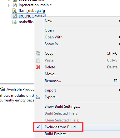
Final step, before we compile, is to add the IR generation driver to the build. Hightlight `IRGENCC26XX.c`, right-click and uncheck the __Exclude from build__ option.
Compile and run!
[[d-question-sign What happens when you press the button now?
[quiz]
v> Same as before
x> IR signal is generated
[quiz]
]]
Task 1 - Generate IR signal
==================================
Now that we have integrated the IR generation driver, it is time to use it!
We will generate IR signals when a user presses button. We already do something when a user presses the button. So, we know where to start the signal.
Modify `pinTaskFunc` as follows:
```c
Void pinTaskFunc(UArg arg0, UArg arg1)
{
irgenParams.markBuffer = markBufferExample;
irgenParams.spaceBuffer = spaceBufferExample;
irgenParams.bufferSize = sizeof(markBufferExample)/sizeof(uint16_t);
while (1) {
Semaphore_pend(keyInterruptSem, BIOS_WAIT_FOREVER);
/* Debounce 25ms */
Task_sleep(25 * (1000 / Clock_tickPeriod));
/* Then safely read IO */
if (PIN_getInputValue(Board_BUTTON0) == 0)
{
/* Button is pressed, so generate IR signal */
/* Open IRGEN handle*/
irgenHandle = IRGENCC26XX_open(&irgenParams);
PIN_setOutputValue(pinHandle, Board_LED0, 1);
IRGENCC26XX_startIrGen(irgenHandle);
Semaphore_pend(irgenSem, BIOS_WAIT_FOREVER);
PIN_setOutputValue(pinHandle, Board_LED0, 0);
/* Close IRGEN handle*/
IRGENCC26XX_close(irgenHandle);
}
}
}
```
First we have updated the parameters to start the IR generation driver with. We have added pointers to the example buffers and updated the size.
```c
irgenParams.markBuffer = markBufferExample;
irgenParams.spaceBuffer = spaceBufferExample;
irgenParams.bufferSize = sizeof(markBufferExample)/sizeof(uint16_t);
```
Next we need to
1. Open the driver
2. Start the signal
3. Wait for signal to complete
4. Close the driver
```c
/* Open IRGEN handle*/
irgenHandle = IRGENCC26XX_open(&irgenParams);
IRGENCC26XX_startIrGen(irgenHandle);
Semaphore_pend(irgenSem, BIOS_WAIT_FOREVER);
/* Close IRGEN handle*/
IRGENCC26XX_close(irgenHandle);
```
In order to make the Semaphore `irgenSem` available, we have to define it. We are going to create this Semaphore statically using the TI-RTOS `.cfg` file instead of instantiate it statically via the code.
* Open the TI-RTOS configuration file (`flash_debug.cfg`) and make sure the TI-RTOS tab is selected.
* On the right side in the `Outline` window, select `Semaphore`
* On the top of the main configuration view, select `Instance`
* Then create a binary semaphore named `irgenSem` and save your changes
[[y! To check that the Semaphore was added
You can verify that the Semaphore instance was added statically by opening `flash_debug.cfg` where you can find the following snippet in bottom of the file:
```js
var semaphore1Params = new Semaphore.Params();
semaphore1Params.instance.name = "irgenSem";
semaphore1Params.mode = Semaphore.Mode_BINARY;
Program.global.irgenSem = Semaphore.create(null, semaphore1Params);
```
]]
[[d-question-sign Waiting for signal to complete.
We are pending on a semaphore. This assumes that the semaphore will be posted when the IR signal has completed. Will this ever happen?
[quiz]
x> Yes
v> Not yet
[quiz]
]]
As we have discovered, we need to post a semaphore when the IR signal has completed. This is one of the things that the callback function is for.
[[b! IR generation driver callback
The IR generation driver calls our callback function for two conditions.
1. When the active part of the signal has been transmitted
2. When the complete signal, which include the repeat period, has been transmitted
]]
[[d-question-sign What does the repeat period mean here?
[quiz_multi]
v Last space as defined in the signal buffer
x Interval between each button press
v Period to hold off until next signal is generated, if button remains pressed
[quiz_multi]
]]
Update the callback function as follows:
```c
static void IRGENCC26XX_callbackFxn(IRGENCC26XX_Handle handle, bool done)
{
/* IR engine generates two interrupts
* 1. After end of active part of signal, just before the repeat period. It is safe to schedule next signal now.
* 2. After end of repeat period. This is only called if there are no pending signals. */
if (done)
{
/* IR engine has completed generation of the signal, and there are no pending signals. */
Semaphore_post(irgenSem);
}
else
{
/* Here we can safely update the buffers for next signal.
* Utilizing the repeat period!
*/
}
}
``` IR generation callback function
[[d-question-sign What happens when you press the button now?
[quiz]
x> Same as before
v> IR signal is generated
[quiz]
]]
Now that we have updated the source as required, hit the build button and run the program! Press the button labeled BTN-1 to trigger IR generation. To see the IR signal connect your favorite logic analyzer, or oscilloscope, to DIO1.
Task 2 - Keep transmitting IR signal
==================================
If the button is kept pressed we want to keep transmitting IR signals. The IR generation driver anticipated this. There are two additional functions to assist with this:
1. `Void IRGENCC26XX_prepareNextSignal(IRGENCC26XX_SubParams *irParams)`
2. `Void IRGENCC26XX_kickNextSignal()`
As we learned in the previous task, the IR generation driver calls our callback function two times per signal. Now we are interested in the first callback. This signals us that we can prepare a new signal. If a new signal is prepared before the current has finished its repeat period, then the IR generation driver will start a new signal instead of calling the callback function at the end of the repeat period.
If we leave the IR generation driver open after it has finished its current signal, we can use the additional APIs to kick off a new signal. To save power,
the driver should be closed as soon as no more signals need to be generated.
Let's do it!
First we need to define the signal we will transmit for the repeats. In our case we'll just reuse the same signal. Add the following to `pinTaskFunc`
```c
IRGENCC26XX_SubParams irParams;
irParams.carrierPeriod24MHz = irgenParams.carrierPeriod24MHz;
irParams.markBuffer = irgenParams.markBuffer;
irParams.spaceBuffer = irgenParams.spaceBuffer;
irParams.bufferSize = irgenParams.bufferSize;
```
Next we will wait for the active part to end, and then check if the button is still pressed.
```c
/* First we wait for active part of signal to end */
Semaphore_pend(irgenSem, BIOS_WAIT_FOREVER);
/* Keep transmitting while button is pressed */
while (PIN_getInputValue(Board_BUTTON0) == 0)
{
```
Then we can prepare our next signal, and wait for next active part to end, before we check the button again.
```c
/* Then we can prepare the same signal again */
IRGENCC26XX_prepareNextSignal(&irParams);
/* Before we wait for active part to end again */
Semaphore_pend(irgenSem, BIOS_WAIT_FOREVER);
}
```
Finally, when the button is no longer detected we will wait for the repeat period to end, as well.
```c
/* Now wait for repeat period to end */
Semaphore_pend(irgenSem, BIOS_WAIT_FOREVER);
```
Your `pinTaskFunc` should now look like this
```c
Void pinTaskFunc(UArg arg0, UArg arg1)
{
irgenParams.markBuffer = markBufferExample;
irgenParams.spaceBuffer = spaceBufferExample;
irgenParams.bufferSize = sizeof(markBufferExample)/sizeof(uint16_t);
IRGENCC26XX_SubParams irParams;
irParams.carrierPeriod24MHz = irgenParams.carrierPeriod24MHz;
irParams.markBuffer = irgenParams.markBuffer;
irParams.spaceBuffer = irgenParams.spaceBuffer;
irParams.bufferSize = irgenParams.bufferSize;
while (1) {
Semaphore_pend(keyInterruptSem, BIOS_WAIT_FOREVER);
/* Debounce 25ms */
Task_sleep(25 * (1000 / Clock_tickPeriod));
/* Then safely read IO */
if (PIN_getInputValue(Board_BUTTON0) == 0)
{
/* Button is pressed, so generate IR signal */
/* Open IRGEN handle*/
irgenHandle = IRGENCC26XX_open(&irgenParams);
PIN_setOutputValue(pinHandle, Board_LED0, 1);
IRGENCC26XX_startIrGen(irgenHandle);
/* First we wait for active part of signal to end */
Semaphore_pend(irgenSem, BIOS_WAIT_FOREVER);
/* Keep transmitting while button is pressed */
while (PIN_getInputValue(Board_BUTTON0) == 0)
{
/* Then we can prepare the same signal again */
IRGENCC26XX_prepareNextSignal(&irParams);
/* Before we wait for active part to end again */
Semaphore_pend(irgenSem, BIOS_WAIT_FOREVER);
}
/* Now wait for repeat period to end */
Semaphore_pend(irgenSem, BIOS_WAIT_FOREVER);
PIN_setOutputValue(pinHandle, Board_LED0, 0);
/* Close IRGEN handle*/
IRGENCC26XX_close(irgenHandle);
}
}
}
```
[[d-question-sign Will this work?
[quiz]
x> Yes
v> No
[quiz]
Why?
[quiz]
x The IR generation driver will call back twice per signal
v The call back does not post the semaphore for callback generated when active part of signal has completed
[quiz]
]]
We must make sure to post the semaphore also when the IR generation driver calls back because active part of signal has completed.
Modify `IRGENCC26XX_callbackFxn` as follows
```c
static void IRGENCC26XX_callbackFxn(IRGENCC26XX_Handle handle, bool done)
{
/* IR engine generates two interrupts
* 1. After end of active part of signal, just before the repeat period. It is safe to schedule next signal now.
* 2. After end of repeat period. This is only called if there are no pending signals. */
if (done)
{
/* IR engine has completed generation of the signal, and there are no pending signals. */
Semaphore_post(irgenSem);
}
else
{
/* Here we can safely update the buffers for next signal.
* Utilizing the repeat period!
*/
Semaphore_post(irgenSem);
}
}
```
[[b! IR generation driver call backs
The IR generation driver does not call back, at the end of repeat period, in case there's a pending signal.
This is why we can go directly from preparing the next signal to wait for the end of next active part. If the IR generation driver had called back for the end of repeat, even when there was a pending signal, we would have had to pend twice.
]]
Try short button presses
----------------------------------
Press the button quickly and see what happens.
[[d-question-sign Why is a signal generated after the button is released? Multiple answers may be correct
[quiz]
x The IR generation driver wants to
v While waiting for next active period to end we do not check for release
[quiz]
]]
We poll the button only right after the active part of an IR signal has completed.
Task 3 - IR generation debugging signals
==================================
As discussed in the first task, we have defined 4IOs for IR generation driver. This even though the IR generation driver only produces one output. The other three IOs are used to output debugging signals.
To enable these signals we have to define `IRGENCC26XX_DEBUG`. Like we decided to define `TI_DRIVERS_IRGEN_INCLUDED` in `CC2650_LAUNCHXL.h`, we do the same now.
Add the following to `CC2650_LAUNCHXL.h`.
```c
#define IRGENCC26XX_DEBUG
``` Add support for IR debug signals via define in `CC2650_LAUNCHXL.h`
Epilogue
==================================
This example has given a hands on in how to integrate and use the IR generation driver. It is now up to you to generate your favorite IR signals!