Introduction
==================================
This lab serves as an introduction to TI's Simple Network Processor + Simple Application Processor. The Simple Network Processor makes it easy to add BLE to an existing MCU solution, or to quickly get started on a dual MCU design. Topics covered in this lab include BLE custom profile management, unified network procesor interface, and the SAPLib.
Prerequisites
==================================
Suggested SimpleLink Academy Labs
---------
* TI-RTOS Basics
* Bluetooth low energy Fundamentals
* Bluetooth low energy Custom Profile
Software for Desktop development
---------
* CCS version 6.1 or later with MSP432 processor support (tested with version `6.1.3` and `6.2.0`)
* TI-RTOS for MSP43x version (tested with version `2.20.0.06`)
* https://www.ti.com/tool/ti-rtos
* TI BLE SDK 2.2.1 (https://www.ti.com/ble-stack)
* MSP Connectivity Library 1.10.03.01 (https://software-dl.ti.com/msp430/msp430_public_sw/mcu/msp430/msp_connectivity_library/latest/index_FDS.html)
* TI BLE Device Monitor (https://www.ti.com/lit/zip/swrc258)
* PuTTy or similar serial console (https://www.putty.org/)
* SmartRF Flash Programmer 2 (Optional: For reprogramming CC2650 Module BoosterPack)
* https://www.ti.com/tool/flash-programmer
[[r! Compiler Support
The BLE-Stack v 2.2.1 SDK release has been built and tested with TI ARM Compiler `v5.2.6`. Compatibility with other TI ARM Compiler versions in CCS has not been tested and use of other compiler versions may result in undefined behavior. Refer to Section 2.6.3.2 of the [BLE Software Developer's Guide (SWRU393)](https://www.ti.com/lit/pdf/swru393) for the procedure to install TI ARM Compiler `v5.2.6`.
]]
Hardware
---------
* 1x MSP432 LaunchPad (red board)
* 1x CC2650 Module BoosterPack
* Micro-USB Cable
* (optional) 10-pin JTAG debug cable
* (optional) CC2540 USB Dongle
About the Simple Network/Application Processor
==================================
Before getting started with the labs, let's go over some of the basics of network processor projects. TI has created a wealth of resources to support the `simple_np` and application processor projects. For supplementary reading, it is recommended that the user take a look at the resources in the table below:
| Resource | Purpose |
| ------------- |:-------------:|
| [BLE Network Processor Wiki](https://processors.wiki.ti.com/index.php/CC2640_BLE_Network_Processor) | A high level page describing network processor options for the CC2640 |
| [Unified Network Processor Interface](https://processors.wiki.ti.com/index.php/Unified_Network_Processor_Interface) | Page describing the technical implementation of the transport layer between NP and AP devices |
| [Simple Network Processor API Guide](https://processors.wiki.ti.com/images/8/8a/CC2640_Simple_Network_Processer_API_Guide.pdf) | PDF that explains the commands that can be sent to the SNP over a serial link. This guide can be found in the documents folder of the BLE-Stack |
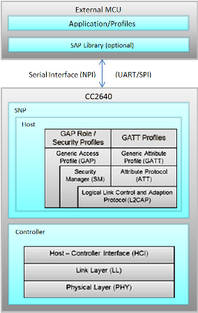
A block diagram of the `simple_np`/application processor system is shown below.
SimpleNP
-------------------
The `simple_np` is the simplified network processor. From the diagram above it can be seen that the entire BLE stack resides on the `simple_np`. This means that all of the BLE protocol processing is done by the `simple_np`, thus freeing up the application processor for other tasks.
### Remote procedure calls
The application processor can configure the `simple_np` in a number of ways, using an API that is based on serial `Remote Procedure Calls`. The serial protocol used to encode the procedure calls is called `Unified Network Processor Interface (UNPI)`. The `UNPI` is a transport layer that is developed by TI to implement a link to the `simple_np` that is standarized across multiple physical tranports such as SPI and UART. It can also be used for user-implemented procedure calls, for example offloading control of an external sensor to the network processor. `UNPI` will be covered in greater depth later in the lab. A link to the detailed UNPI protocol description is given in the table above.
Using `UNPI` as the serial transport protocol, the `simple_np` can be configured and controlled using the specific `simple_np` serial API described in the `Simple Network Processor API Guide` in the table above.
### Modes of operation
Currently, the `simple_np` supports the `Peripheral` GAP role, and thus is ideal for a dual MCU solution to allow connections to be made to the device from, for example, a smart phone.
Covered in more detail later, the `simple_np` API allows the user to define specific services on the application processor, which will be visible to peer devices over the air, and to control the content of the always present `Generic Access Service` and `Device Information Service`. As these are always present, and requests to read these are handled by the `simple_np`, no space is wasted on the application processor.
ProjectZero Task
-------------------
[[b> Profiles/Services
Profiles describe how certain Services should be used. Services are a collection of characteristics, which in turn are the primary vehicle for transmitting data over BLE.
To learn more about services and how they work, complete the [Bluetooth low energy Basics](../ble_01_basic/ble_01_basic.html) and [Bluetooth low energy Custom Profile](../ble_01_custom_profile/ble_01_custom_profile.html) labs.
]]
The `ProjectZero` project for MSP432 is provided as a sample application processor task which controls the CC2650 Module BoosterPack network processor via a serial interface.
The `ProjectZero` project used in this demo is designed to run on an MSP432 device, but thanks to the `SAPLib`, it can be easily ported to other TI-RTOS capable processors such as Stellaris, CC3200, or another CC26xx device.
The application processor is responsible for maintaining custom profiles. When data from custom profile is requested by a wireless peer device, a serial UNPI request is received by the application processor. The appication processor then has the choice of remembering a stored value and transmitting that back, or actively computing the requested value. Similarly when the application processor wants to write data to a central device, it will notify the `simple_np`.
SAPLib
-------------------
The `SAPLib` is a reference project provided in source by TI to translate local `simple_np` API function calls into remote serial requests to the network processor and to parse the response.
Contained in the SAP library project is
* A master-side implementation of the Unified Network Processor Interface(UNPI)
* The entire BLE SNP subsystem that handles framing `UNPI` commands to be sent to the `simple_np`, and
* An abstraction / translation layer for these commands.
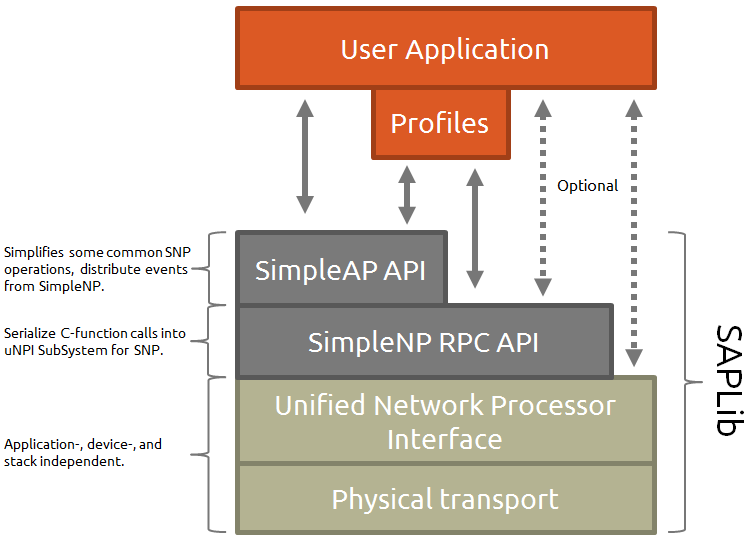
The user needs to only build the `SAPLib` for their selected TI-RTOS capable processor and interface with the API to get started with BLE. Since the library is provided in source, the low level functionality may be modified, such as adding a custom `UNPI` subsystem to handle peripheral control in addition to `simple_np` commands. See the graphic below for the composition of the `SAPLib`.
[[d What services are manged by the SimpleNP?<br>(multiple correct answers)
[quiz_multi]
x> Serial Port Profile (SPP)
v> Generic Access Service
x> Link Loss Service (LLS)
v> Device Information Service
x> Simple Profile
[quiz_multi]
]]
[[d Select the layers encapsulated in the SAP Library.<br>(multiple correct answers)
[quiz_multi]
v> UNPI UART/SPI transport layer
v> UNPI BLE Subsystem
x> User Application callbacks
x> TI-RTOS drivers
v> SNP RPCs
[quiz_multi]
]]
UNPI
-------------------
The Unified Network Processor interface handles the framing and sending of serial data between the application processor and the `simple_np`. The `simple_np` supports UART or SPI transport layers, UNPI sits above these protocols and interfaces with their drivers.
To better understand how the system works and how the two processors interact, we will trace a Characteristic Write Indication from the `simple_np` to the application processor.
###Serial Link
When the central device (i.e. BLE Device Monitor) writes a characteristic such as char3, the `simple_np` does the necessary BLE protocol stack processing, and then-if the characteristic is managed by the application processor-forwards this request to the application processor task for further processing. A sample logic capture of the `UNPI` frame corresponding to a write request is shown below.
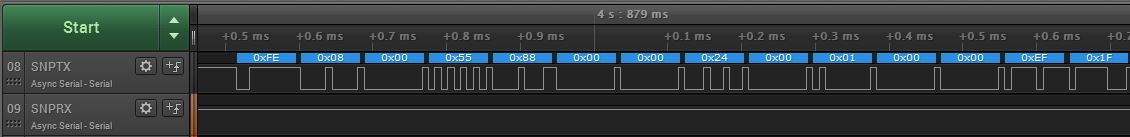
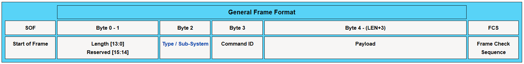
Look at the Unified NPI Frame Format taken from the [Unified Network Processor Interface](https://processors.wiki.ti.com/index.php/Unified_Network_Processor_Interface) wiki page shown below. Try to decode the frame format.
[[d Quiz
Based on the `UNPI` frame from the logic trace above, what is the value of the CMD0 field?
[quiz]
x> 0xFE
x> 0x88
v> 0x55
[quiz]
]]
###SNP API
Now try and match the payload of the above frame to this excerpt from the `simple_np` API guide on the Characteristic Write Indication command. All supported SNP API commands are detailed in this document.
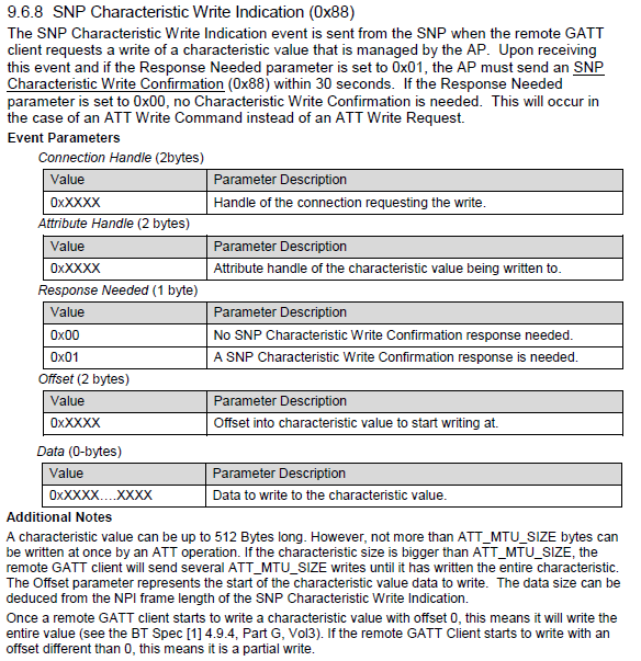
[[d Quiz
Does the application processor need to respond to this indication?
[quiz]
x> No
v> Yes
[quiz]
]]
###SAPLib Code
The `UNPI` interface is implemented as a task running on the SAP device. Upon receiving this command the over serial interrupts and callbacks will be triggered in the `UNPI` code to read the frame into the application processor. The CMD0 field indicates whether the command was synchronous or asynchronous. Based on CMD0, corresponding RPC will be kicked off. This is forwarded up the SAP abstraction layer, which will then trigger the proper callback within the application layer. Since this is all in the provided library, the application processor developer doesn't need to modify this code except for custom use cases.
###Application Processor Task
After opening the SAP module from the `SAPLib` using SAP_open the application processor is ready to send and recieve `UNPI` frames. Before this however, the application processor task (i.e. ProjectZero) makes a call to `LEDService_registerAppCBs(), ButtonService_registerAppCBs(), and DataService_registerAppCBs()` in it's init function, which allows the application layer to be notified of changes in the LED service, button service, and data service. Specifically the `ProjectZero_processLEDServiceCB` callback function is executed whenever the `simple_np` sends a write indication to the application processor for a characteristic in the LED service.
Getting Started
==================================
Set up Desktop Environment
-------------------
1. Make sure CCS is installed ( version 6.1 or later) with MSP432 Processor Support. If you have already installed CCS without selecting MSP432 device support, you can add the necessary packages by re-running your CCS installer and selecting MSP432 Ultra Low Power MCUs box under the MSP Ultra Low Power MCUs. header.
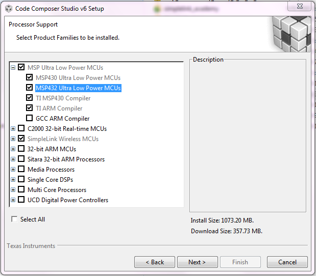
You can find version info in the menu 'Help->About Code Composer Studio'
2. Make sure TI-RTOS for MSP43x is installed. If it is installed to the default directory, it should be located here:
`C:\ti\tirtos_msp43x_2_20_00_06`
3. Make sure TI MSP Connectivity Library is installed. If it is installed to the default directory, it should be located here:
`C:\ti\msp_connectivity_library_1_10_03_01`
4. Make sure TI BLE Stack v2.2.x is installed. If it is installed to the default directory, it should be located here:
`C:\ti\simplelink\ble_sdk_2_02_01_18`
Setup LaunchPad Hardware
------------------------
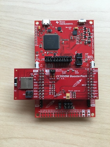
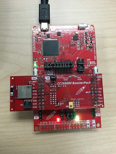
This demo will use an MSP432 Launchpad and a CC2650 Module BoosterPack seated together via the BoosterPack connector.
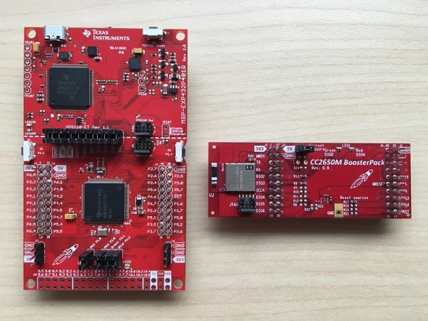
**Stack the LaunchPads**
* Connect the male BoosterPack headers on the MSP432 LaunchPad to the female headers on the CC2650 Module BoosterPack.
* Make sure all pins are aligned
Task 1 – Run the Demo
==================================
You will now configure and set up the `ProjectZero` project for the MSP432 in CCS, load it onto the LaunchPad and run the demo applications. The CC2650 Module BoosterPack is preprogrammed with the `simple_np` project. If you need to reflash the CC2650 Module BoosterPack with the `simple_np` hex file, see the instructions in the [Reprogramming CC2650 Module BoosterPack](#reprogramming-cc2650-module-boosterpack) section.
Import to Code Composer Studio
------------------------
* Using the CCS Resouce Explorer(view --> Resource Explorer) navigate to the `MSP432_ProjectZero` project in the projects tab under Bluetooth low energy in SimpleLink Academy as seen in the image below.
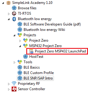
* Press on the `Import the example project into CCS`
* Compile the project (<kbd>Ctrl + B</kbd>, the hammer icon, or via Resource Explorer)
Loading the Firmware
------------------------
We will now program the MSP432 LaunchPad. Note that when you click on a project in CCS it becomes the 'Active' project. This can be verified by looking for the `[Active - Debug]` tag to the right of their name.
* **Load the MSP432_ProjectZero project** onto the LaunchPad
1. Attach the micro-USB cable to to the MSP432 LaunchPad.
2. Select the `MSP432_ProjectZero` project by single clicking it.
3. Hit the bug symbol or (<kbd>F11</kbd>) to load the project into Flash and launch a debug session.
4. You can can click <kbd>F8</kbd> or the Play/Pause symbol to start execution
Configure the Terminal Application
---------------------
* If not done, connect the top LaunchPad running `MSP432_ProjectZero` project to the computer using the micro USB cable.
* The Windows Device Manager (Start → Run → `mmc devmgmt.msc` → Ok) should show you the following devices connected:
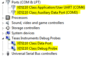
* Note the COM port number of the `XDS110 Class Application/User UART` listed.
* Configure putty as a serial console with 115200 8N1.
* Fill in the Serial Line field with the COM port from above.
* When configured correctly, the program should look as below:
[[b Putty sessions
It is recommended to save these settings as a configuration using the save button. Saved sessions can be restored using the load button.
It is sometimes necessary to overcome Virtual COM port issues in Windows by re-plugging the device, and a saved session can save on frustration.
**Note:** If you re-insert the USB cable in a different physical port on the computer, the COM port name will change.
]]
| Main Screen | Serial Screen |
|: ------------- :|:-------------:|
| 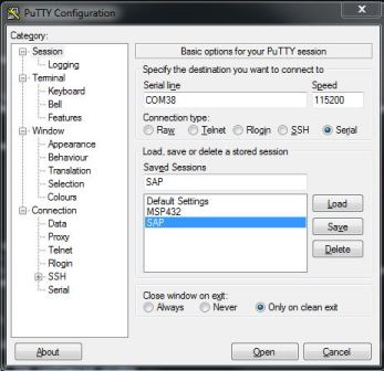 | 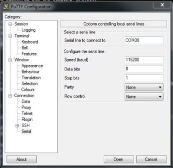|
**You may need to unplug/replug your launchpad and restart PuTTY if you do not see any output. See the [No output on PuTTY](#no-output-in-putty) section**
Hello World
--------------------
When the application runs as expected, you should see the something like the following output in your terminal emulator:
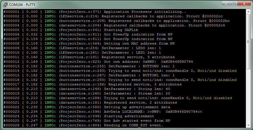
This is logging data that the sample application has been instrumented with, which is captured via the TI-RTOS Log system and output via UART to your PuTTY terminal.
The first column is event number, the next is system time in seconds, and the following is file and line number of the log statements along with the message.
You will notice that the services (for data exchange) are dealing with the necessary `simple_np` actions pertaining to each service:
* Adding / registering the service
* Sends the data structure to the NP
* Tells `SAPLib` about callbacks for writes and reads.
* Registering for callbacks on connection establishment
* To re-initialize a state variable
On the second line you also can see that the profile is initialized with user-functions to call if a valid write is received.
Finally you can see that the main application sets up the `simple_np` to start advertising and waits for a connection.
Cutting the wires
---------------------
Now that the `simple_np` is advertising on your command, it is visible to the outside world. Using your cell-phone or the TI BLE Device Monitor you can scan for the device's advertisement packets.
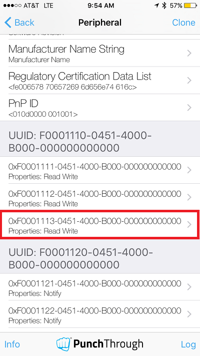
**iOS: Connect via LightBlue**
1. Download the LightBlue application from the App Store
2. On opening the LightBlue application, nearby BLE devices are shown. To refresh the list, pull down on the list.
3. Tap on the "Project Zero" device to connect to it, expand the Advertisement Data section to see the Device Name. Scroll down to see the attributes
4. Tap on a characteristic to investigate it further, if the selected characteristic has write permissions you can write to it by tapping Write new value
5. Write '1' to the 2 characteristics that belong to the LED service (UUID starts with F000111x).
| Step 2 | Step 3 |
| :-------------: | :-------------:|
| 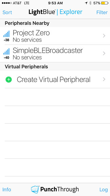| 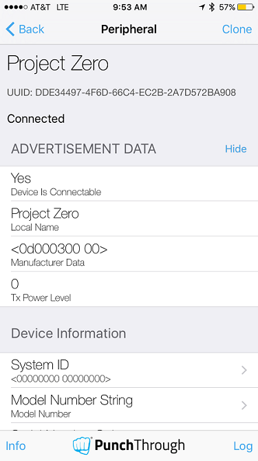 |
| Step 4 | Step 5 |
| :-----:| :-----:|
| 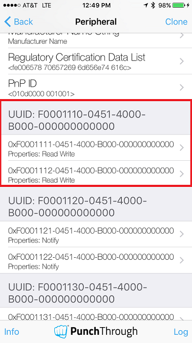 |  |
[[y iOS Device Name
Note: That if iOS has previously bonded with the same device it will remember it's old name. To fix this, close your app and turn off and on the Bluetooth on your phone.
]]
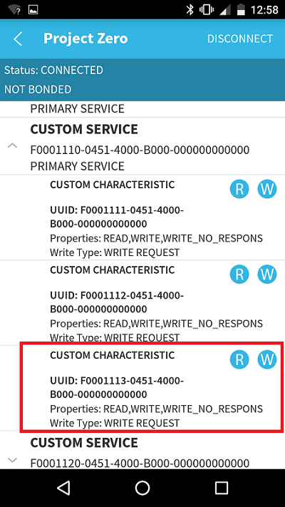
**Android: Connect via BLE Scanner**
1. Download the BLE Scanner application from the App Store
2. On opening the BLE Scanner application, nearby BLE devices are shown.
3. Tap on the connect button to the right of the Project Zero Device Listing.
4. Once the connection is established, BLE Scanner will show the attributes of the Project Zero device, tap on the W button to the right of the characteristic listings for the first custom service to write its value
5. Enter '1' for both characteristics, if using hexidecimal notation, then be sure to select the byte array option, otherwise the ASCII value will be used.
| Step 2 | Step 3 |
| :-------------:| :-------------:|
| 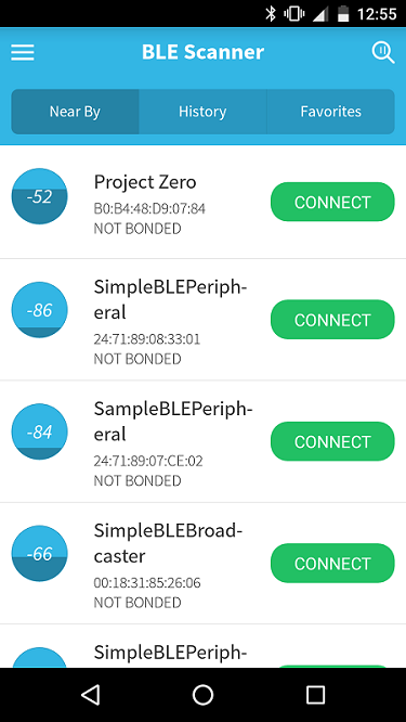|  |
| Step 4 | Step 5 |
|:-------------:| :-----:|
|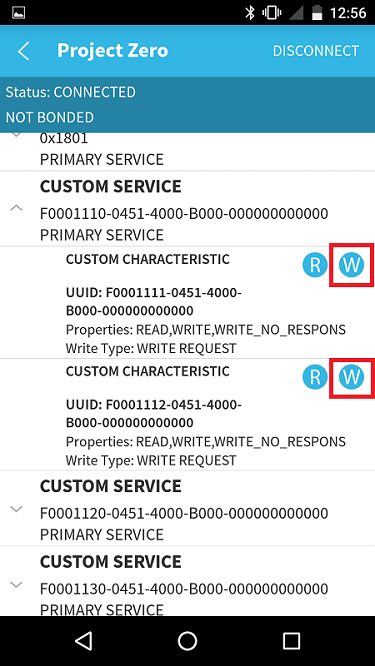 |  |
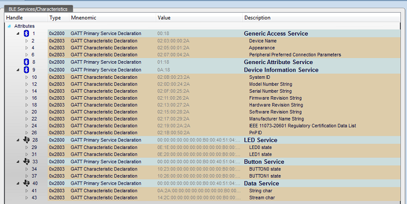
**Desktop: Connect via BLE Device Monitor**
If you have a CC2540USB dongle running the HostTest application included in the TI BLE SDK v1.4.1, or a CC2650 evaluation module running the HostTest application included in the TI BLE SDK v2, you can use the BLE Device Monitor to discover, connect to and explore your `simple_np` device. For instructions on how to use BLE Device Monitor, please see the section in [Bluetooth low energy Basics](../ble_01_basic/ble_01_basic.html). BLE Device Monitor will show all services registered with the `simple_np` as below.
Using your central device of choice, play around with the services on Project Zero. Try changing other characteristics and notice the output on the PuTTY terminal.
Once you've connected from any Central device, the output on the UART will look something like this:

[[d Quiz
What device is the value of Characteristic 3 stored on?
[quiz]
x> CC2650 Module BoosterPack
x> UNPI
v> MSP432 Launchpad
[quiz]
]]
[[d Quiz
How is the application processor task notified of a Characteristic Write Indication to char3?
[quiz]
x> It parses serial data
x> It isn't notifed
v> An application callback is triggered
[quiz]
]]
Task 2 – Change the Advertised Name
==================================
The advertised name is a plain text field that can be contained in the advertisement or scan response data structures. This field is then visible to bluetooth devices that are scanning. Scanning and scan responses are part of the BLE discovery process where a central device can gather more information about the peripheral devices that are currently advertising nearby. By default this field is set to "Project Zero". In order to make your device unique, we will change it's name.
For the Simple Network Processor, the application processor needs to use the SAP API to initialize the advertisement and scan response arrays. When advertisement starts, these arrays are exposed to interested parties.
### How it's set up
During initialization or at some other point at run-time, the application processor tells the `simple_np` what data to use as a response to a scan request.
* Scan response data can be set using an API found in the `SAPLib`.
* Specifically `Project Zero` will call `SAP_setParam(...);` after it has gotten confirmation that that the `simple_np` is initialized.
* See the UART output for the line number where this happens.
### What to do
Find the `scanRspData` array in the `ProjectZero.c` file and modify your device's name. Remember to update the length field if you change the number of bytes in this field.
```c
/* GAP - SCAN RSP data (max size = 31 bytes) */
static uint8_t scanRspData[] =
{
// complete name
0x0D,// length of this data
SAP_GAP_ADTYPE_LOCAL_NAME_COMPLETE, 'P', 'r', 'o', 'j', 'e', 'c', 't', ' ',
'Z', 'e', 'r', 'o',
// connection interval range
0x05,// length of this data
0x12, //SAP_GAP_ADTYPE_SLAVE_CONN_INTERVAL_RANGE,
LO_UINT16(DEFAULT_DESIRED_MIN_CONN_INTERVAL), HI_UINT16(
DEFAULT_DESIRED_MIN_CONN_INTERVAL), LO_UINT16(
DEFAULT_DESIRED_MAX_CONN_INTERVAL), HI_UINT16(
DEFAULT_DESIRED_MAX_CONN_INTERVAL),
// Tx power level
0x02,// length of this data
0x0A, //SAP_GAP_ADTYPE_POWER_LEVEL,
0 // 0dBm
};
``` **ProjectZero.c**
Task 3 – Add a New Characteristic to the LED Service
==================================
In this task we will use our knowledge from Task 1 to edit the LED Service in `ProjectZero` to change the colors of the tricolor LED on the MSP432 based on BLE. The ProjectZero_processLEDServiceCB is code that is executed when a Characteristic Write on characteristic in an LED service is sent to the application processor. By modifying this code, we can control the tricolor LED on the application processor board over BLE.
The tricolor LED is configured in the `MSP_EXP432P401R.c` file and initialized in the `main.c` before the BIOS starts.
```c
GPIO_PinConfig gpioPinConfigs[] =
{
...
/* MSP_EXP432P401R_LED_RED */
GPIOMSP432_P2_0 | GPIO_CFG_OUT_STD | GPIO_CFG_OUT_STR_HIGH | GPIO_CFG_OUT_LOW,
/* MSP_EXP432P401R_LED_GREEN */
GPIOMSP432_P2_1 | GPIO_CFG_OUT_STD | GPIO_CFG_OUT_STR_HIGH | GPIO_CFG_OUT_LOW,
/* MSP_EXP432P401R_LED_BLUE */
GPIOMSP432_P2_2 | GPIO_CFG_OUT_STD | GPIO_CFG_OUT_STR_HIGH | GPIO_CFG_OUT_LOW,
...
}
Void main()
{
...
Board_initGPIO();
...
BIOS_start()
}
```
The LEDs are turned on and off based on the values sent to the LED service. As seen in Task 1, the default project allows you to control the red LED and the green LED by sending writes to char0 and char1, respectively, in the LED service. We will add an additional characteristic that can be used to control the blue LED.
We will start by modifying the header file `LEDservice.h`.
```c
//Add definitions for a 3rd LED Characteristic
// Characteristic Types - These must be listed in order that they appear
// in service
#define LED_CHAR0 0x00
#define LED_CHAR1 0x01
#define LED_CHAR2 0x02
#define LS_LED0_ID SENSOR_ID_CREATE(LED_CHAR0,SENSOR_VALUE)
#define LS_LED1_ID SENSOR_ID_CREATE(LED_CHAR1,SENSOR_VALUE)
#define LS_LED2_ID SENSOR_ID_CREATE(LED_CHAR2,SENSOR_VALUE)
// LED Service UUID
#define LED_SERVICE_UUID 0x1110
// LED Characteristic UUIDs
#define LS_LED0_UUID 0x1111
#define LS_LED1_UUID 0x1112
#define LS_LED2_UUID 0x1113
#define LS_LED0_LEN 1
#define LS_LED1_LEN 1
#define LS_LED2_LEN 1
#define LS_LED0_LEN_MIN 1
#define LS_LED1_LEN_MIN 1
#define LS_LED2_LEN_MIN 1
```
Next we will modify the implementation file `LEDservice.c`
```c
//Increase the number of characteristics supported
#define LED_NUM_ATTR_SUPPORTED 3
//Create a UUID for LED2
// LED_Service Service UUID
static uint8_t LEDServiceUUID[SNP_128BIT_UUID_SIZE] =
{ TI_BASE_UUID_128(LED_SERVICE_UUID) };
// LED0 UUID
static uint8_t ls_LED0UUID[SNP_128BIT_UUID_SIZE] =
{ TI_BASE_UUID_128(LS_LED0_UUID) };
// LED1 UUID
static uint8_t ls_LED1UUID[SNP_128BIT_UUID_SIZE] =
{ TI_BASE_UUID_128(LS_LED1_UUID) };
// LED2 UUID
static uint8_t ls_LED2UUID[SNP_128BIT_UUID_SIZE] =
{ TI_BASE_UUID_128(LS_LED2_UUID) };
//Create the LED2 Value Variable and data length in Profile Attributes - TYPEDEFS
/*******************************************************************************
* Profile Attributes - TYPEDEFS
******************************************************************************/
...
// Characteristic "LED1" Value variable
static uint8_t ls_LED1Val[LS_LED1_LEN] = {0};
// Length of data in characteristic "LED1" Value variable, initialized to minimal size.
static uint16_t ls_LED1ValLen = LS_LED1_LEN_MIN;
// Characteristic "LED2" Value variable
static uint8_t ls_LED2Val[LS_LED2_LEN] = {0};
// Length of data in characteristic "LED2" Value variable, initialized to minimal size.
static uint16_t ls_LED2ValLen = LS_LED2_LEN_MIN;
//Create a new entry in the LED PROFILE ATTRIBUTES TABLE with the same permissions
//and properties as the existing entries
// LED2 Characteristic
{
{ SNP_128BIT_UUID_SIZE, ls_LED2UUID }, /* UUID */
SNP_GATT_PROP_READ | SNP_GATT_PROP_WRITE | SNP_GATT_PROP_WRITE_NORSP, /* Properties */
SNP_GATT_PERMIT_READ | SNP_GATT_PERMIT_WRITE, /* Permissions */
/* User Description */
/* CCCD */
/* Format */
},
//Add a case for LED_CHAR2 to LEDService_setParameter
case LED_CHAR2:
pAttrVal = ls_LED2Val;
valMinLen = LS_LED2_LEN_MIN;
valMaxLen = LS_LED2_LEN;
Log_info2("SetParameter : %s len: %d", (IArg)"LED2", (IArg)len);
break;
//Add a case for LED_CHAR2 to LEDService_getParameter
case LED_CHAR2:
memcpy(value, ls_LED2Val, ls_LED2ValLen);
Log_info2("GetParameter : %s returning %d bytes", (IArg)"LED2",
(IArg)ls_LED2ValLen);
break;
//Add a case for LED_CHAR2 to LEDService_ReadAttrCB
case LED_CHAR2:
switch (SENSOR_ID_CHARTYPE(charID))
{
case SENSOR_VALUE:
*pLen = sizeof(ls_LED2Val);
memcpy(pData, ls_LED2Val, sizeof(ls_LED2Val));
isValid = 1;
Log_info3("ReadAttrCB : %s connHandle: %d offset: %d",
(IArg)"LED2",
(IArg)conn,
(IArg)offset);
break;
/* Other considerations for LED2 can be inserted here */
default:
break;
}
break;
//Add a case for LED_CHAR2 to LEDService_WriteAttrCB
case LED_CHAR2:
switch (SENSOR_ID_CHARTYPE(charID))
{
case SENSOR_VALUE:
if (len == sizeof(ls_LED2Val))
{
memcpy(ls_LED2Val, pData, sizeof(ls_LED2Val));
status = SNP_SUCCESS;
notifyApp = LS_LED2_ID;
}
Log_info3("WriteAttrCB : %s connHandle(%d) len(%d)",
(IArg)"LED2",
(IArg)conn,
(IArg)len);
break;
/* Other considerations for LED2 can be inserted here */
default:
break;
}
break;
```
Now that the new characteristic is set up, modify the `ProjectZero_processLEDServiceCB` in `ProjectZero.c` to include a case for the new characteristic. You should now be able to see three characteristics in the LED service. Try turning on and off the LED characteristics to make different colors.
| LightBlue | BLE Scanner |
| :-------------: |:-------------:|
| |  |
Task 4 – Add user input to Button Service
==================================
[[b> GATT Permissions
Characteristic reads, writes, notifications, and indications are handled by the GATT server on the SimpleNP device. Each characteristic is assigned permissions when it is registered with the GATT server that tell the server what operations are legal for this data. To learn more about the GATT characteristics and how they work, complete the [Bluetooth low energy Basics](../ble_01_basic/ble_01_basic.html) and [Bluetooth low energy Custom Profile](../ble_01_custom_profile/ble_01_custom_profile.html) labs.
]]
In the last task we controlled the tricolor LED on the application processor board with a smartphone or PC over BLE. This task will focus on sending status data from the application processor back to the phone. We will accomplish this by controlling the value of a characteristic in the ButtonService with the buttons the CC2650 LaunchPad. When this task is complete we will have a characteristic that tracks the number of button clicks on the application processor board.
Since buttons are a device that are read-only by nature, we shall use a characteristic with similar properties. We will add a read-only characteristic to our button service that will store a value that changes based on button presses. We aim to have the left button (BTN-1) be an up counter, and the right button (BTN-2) be a down counter. For example, if the user hits BTN-1 the value of characteristic 3 will increment and if the user hits BTN-2, the value of characteristic 3 will decrement.
Since the `simple_np` handles sending the data over the BLE link, the application processor needs only to react to a button press, update its record of char2 accordingly, and send the data to the `simple_np`.
Similar to how we saw `LEDService_getParameter` being used in the previous exercise to read the updated value of the LED characteristics, we will write the updated value of char2 using `ButtonService_setParameter`
Just as in the previous task, the necessary drivers to interface to the hardware are given to you. You can see the button configuration in `MSP_EXP432P401R.c`. The functions for detecting key presses and forwarding them to the `ButtonService` are handled in `ProjectZero.c`. The `user_handleButtonPress` function will determine which key was pressed and take the neccessary action on characteristic 3.
Use the same process as in Task 3 to add a new read-only characteristic to the ButtonService by modifying the ButtonService header file and the implementation file to include an additional Button characteristic. Make sure the new characteristic has only read properties and permissions in the `ButtonAttrTable`. (Hint: Characteristic 2 of the `simpleGATTprofile` service is a read-only characteristic)
Modify the `user_handleButtonPress` to increment/decrement a variable and set the value of Button Char 2 based on which button is pressed.
Modify `ButtonService_setParameter` to account for the addition of the new characteristic.
Add a case to `ButtonService_ReadAttrCB` to account for the addition of the new characteristic.
Connect to `ProjectZero` using your central device of choice. If everything was done correctly, a new characteristic should be listed in the Button service and should respond to the button presses appropriately.
[[d Quiz
Suppose that after a custom profile (i.e. Button Service) is initialized, a central device attempts to perform an invalid read or write. This means the cental has tried to write a characeristic that is defined as read only. Which processor will handle this case?
[quiz]
x> application processor
v> simple_np
x> Neither
[quiz]
]]
**Congratulations, you have completed this module! You can find the solution files in the Application and Profiles folders**
Appendix/Troubleshooting
==================================
Can't connect with PuTTY
---------------------
1. Close PuTTY
2. Close all programs that may be attached to the XDS110 (i.e. Code Composer Studio, Smart RF Flash Programmer 2, etc)
3. Unplug/re-plug board
4. Attempt to re-start PuTTY connection
No output in PuTTY
---------------------
1. Unplug the application processor LaunchPad
2. Close putty
3. Plug in the application processor LaunchPad
4. Restore your PuTTY section as described above
5. Click the reset button (located near the USB port), you should output in the terminal
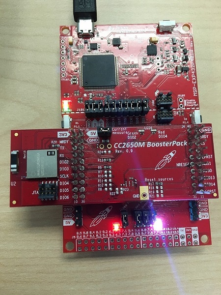
Reprogramming CC2650 Module BoosterPack
---------------------
1. Remove jumpers from XDS110 header pins to isolate the debugger.
2. Connect XDS110 Out on top half of MSP432 LaunchPad to JTAG header on CC2650 Module BoosterPack.
3. Connect the XDS110 to your computer using the micro USB connector.
4. Open SmartRF Flash Programmer 2 and click on the CC2650 option in the 'Connected devices' window.
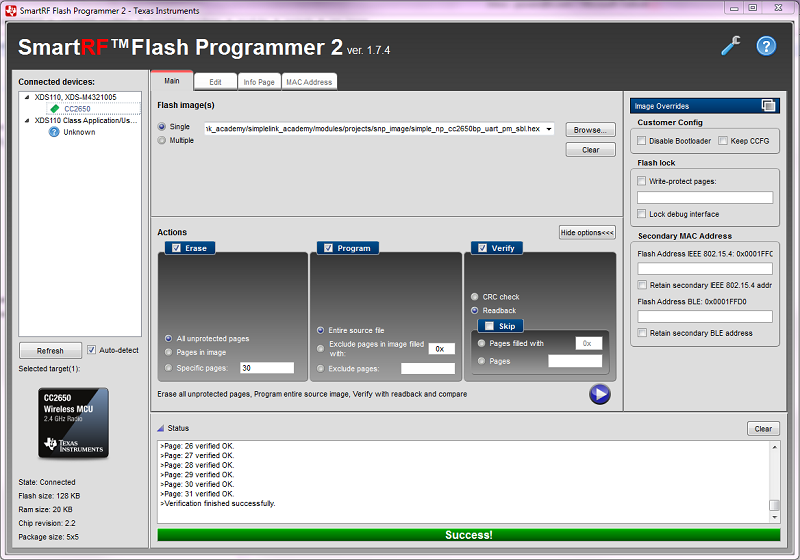
5. In the 'Flash image(s)' section, click 'Browse' and navigate to the `ble_cc26xx\snp_image\cc2650bp` directory of your MSP Connectivity Library install and select the `simple_np_cc650bp_uart_pm_sbl.hex` image.
6. Configure your SmartRF Flash Programmer settings to Erase, Program, and Verify as shown in the above screenshot.
7. Hit the run button. The 'Status' section will show the output. You will see a Success! message when all actions have completed.