OAD Concept Overview
This section aims to explain the major concepts involved in the OAD process from a high level. The concepts here will be expanded upon further in the following sections. Some concepts, such as the Boot Image Manager (BIM), may vary in their implementation details. Wherever possible, the concepts will be covered in this chapter with their implementation details covered in the following chapters.
OAD Types
There are two methods of implementing a firmware update using over the air download process: On-chip and Off-chip. The key difference between the two methods is the location the downloaded image is to be stored during the OAD process. During On-chip OAD, the downloaded image is written to internal flash, allowing for a single chip OAD solution. Off-Chip OAD stores the downloaded image in an external flash part, requiring a two chip OAD solution. Figure 82. shows a comparison of different OAD methods. Each type of OAD has associated trade offs and benefits which will be discussed in their respective sections. Despite their differences, both OAD methods share the same over the air profile and image header described in this section
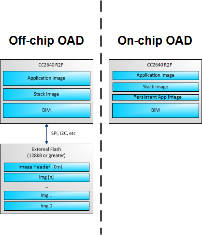
Figure 82. OAD Types Overview
| OAD Type | Advantages | Limitations |
| On-chip |
|
|
| Off-chip |
|
|
OAD Projects
TI offers example projects based on Simple Peripheral for both the On-chip and Off-chip OAD methods. Both types of OAD require BIM, Application, and Stack images. In addition, performing an On-Chip OAD requires a Persistant Application image to support the OAD process. An Off-chip OAD supports both Stack and Stack Library projects. See OAD Projects Overview. for the SimpleLink CC2640R2 SDK example projects that are needed to evaluate the TI OAD Profile.
| OAD Type | BIM Project | Persistant Application Project | Application Project | Stack Project |
| On-chip | bim_oad_onchip_cc2640r2lp_app | persistent_app_cc2640r2lp | simple_peripheral_cc2640r2lp_oad_onchip_app | simple_peripheral_cc2640r2lp_oad_onchip_stack |
| Off-chip | bim_oad_offchip_cc2640r2lp_app | none | simple_peripheral_cc2640r2lp_oad_offchip_app | simple_peripheral_cc2640r2lp_oad_offchip_stack |
- For IAR: All the required projects are part of the Simple Peripheral OAD workspace.
- For CCS: All the required projects are imported when importing the Application project.
Boot Image Manager (BIM)
Since a running image cannot update itself, both On-chip and Off-chip OAD methods must employ a boot image manager (BIM). The BIM is a lightweight section of code that is designed to run every time the device resets, check the validity of newly downloaded images, and if necessary, load the new image into internal flash.
BIM’s implementation varies slightly for On-chip and Off-chip OAD solutions, thus there is a separate BIM project for each.
bim_oad_onchipSee BIM for On-chip OADbim_oad_offchipSee BIM for Off-chip OAD
OAD Topology Overview
Two BLE capable devices are required for implementing the OAD custom GATT service. The terms for the devices involved in an OAD exchange are listed below:
The OAD Target is always the device that implements the OAD service GATT server. Typically this is the peripheral device that is being updated. The OAD Target uses a Boot Image Manager (BIM) to facilitate the application of a new firmware update image. The BIM executes on a device reset and determines if a firmware update is to be applied. If no update is being applied, then the BIM will transfer program execution to the main application image. The behavior of the BIM is dependent upon the selected OAD type and further described in the respective off-chip and on-chip sections below
The OAD Downloader is always the device that implements the OAD service GATT client. Typically this is the central device that is supplying the firmware update image. Figure 83. shows a graphical relationship of the devices required for an OAD transfer. The OAD Downloader can be any compliant BLE device that meets the minimum requirements needed to implement the OAD service (e.g, a smartphone).
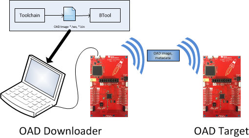
Figure 83. OAD Downloader and OAD Target
All provided TI example applications (BTool, mobile applications, etc.) are implemented such that the OAD Target is a peripheral device, and the OAD Downloader is a central device. Other configurations are outside of the scope of this document.
OAD Process
Image Validation
After establishing a new connection, updating the connection interval for a faster OAD and enabling notifications of OAD Image Identify and OAD Image Block characteristics on the OAD Target, the OAD Downloader shall write to the Image Identify characteristic of the OAD Target. The message data will be the header retrieved from the OAD Image available for OAD.
On receiving the Image Identify message, the OAD Target will verify that the contents of the image can be supported. This is done by checking the Image Header fields, BIM & Metadata versions, and length of the image.
The OAD Target will then perform boundary checks in the case of an Application Only or Stack Only OAD. This is done to ensure no boundary violations will occur between the upgraded image and the images that remain on the device.
The OAD client application will implement an ‘OAD State Machine’ for performing the OAD. The following state machine depicts OAD target application’s state transitions and its interactions with the OAD communication profile messages for both On-chip and Off-chip OAD.
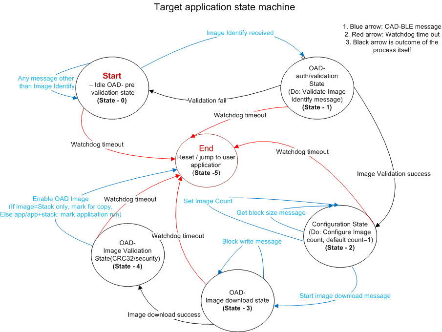
Figure 84. OAD Types Overview
Image Block Transfers
After the Image Validation has completed, the OAD Target will switch to the configuration state. There it will get the block size and set image count. When the OAD Downloader sends the Start OAD Command to the Control Characteristic (for more details see OAD Control Characteristic Supported Commands.), the OAD Target will respond with a Control characteristic notification requesting the first block. The OAD Downloader will then send the first block to the OAD Target.
This process continues with the OAD Target notifying the OAD Downloader of the next block it needs and the OAD Downloader sending the requested image block until all blocks have been transferred.
Completion of the OAD Process
After receiving the complete image, the CRC32 of the entire image will be calculated and the’CRC32 status’ bytes will be set accordingly. If the computed CRC matches with the ‘CRC’ field of received image, it switches to ‘End’ state.
In the ‘End’ state of OAD state machine, the target application processing differs for On-chip and Off-chip OAD.
For On-chip OAD, in the case of a Stack only OAD, the BIM Argument will be used to copy the new Stack image over the existing Stack, then switch back to the Persistent App to download the new Application image. In all other cases, the End state involves updating the BIM Argument variable to switch to the User Application.
For Off-chip OAD, after OAD process is finished, the OAD Target checks that the previous state was OAD Validation. If not, the state machine is reset and any used buffers are freed.
Next, the Application checks to see if there are any more images waiting to be downloaded. If there are, the Application will return to the Image Download state. If there are no more images to download, the OAD Target will check to see if the image that was downloaded should be copied to internal flash.
If the Enable OAD Image Command has been received, the new image will be copied to internal flash and the device will be reset. If not, the currently resident image will continue regular execution.
Handling Errors During the OAD Process
To ensure reliability, any error or faults that occurs during an OAD transfer requires the OAD Downloader to restart the OAD transfer procedure from the beginning. Errors may be reported through the OAD Image Status characteristic if notifications have been enabled
Linker Responsibilities
In general, there are a few bare requirements that the linker command file must have to support the TI OAD Profile, TI Tools, and TI BIM (The TI OAD Ecosystem):
- Flash Space for OAD Image Header and App Start location
- Preservation of Page 31 (CCFGs + BIM) see Handling Errors During the OAD Process
- Alignment of Interrupt Vector Table see Using a custom reset vector address for your application
These requirements are critical; not just to be supported in the TI OAD Ecosystem but for stability of application as discussed in earlier sections.
The SimpleLink CC2640R2 SDK provides cc26xx_app_oad.cmd (CCS) and cc26xx_app_oad.icf (IAR)
linker command files to show these requirements for compatibility with TI OAD
Ecosystem. Example modifications to an existing linker command file to make an
Library OAD off-chip possible is shown in
:ref:sec-generating-library-oad-linker-file.
Generally, the TI Image Tool will handle page alignment of OAD images, no linker intervention is required. However, if desired, some stack side changes can be done to make the stack entry point page aligned, see Stack Side Changes for OAD Project.