3.7. Multimedia Video Codec
3.7.1. Introduction
TI’s embedded processors such as J721E have the following hardware accelerators:
Multi-Standard HD Video Decoder (DECODER) based on D5520MP2 from Imagination Technologies for accelerating multimedia decode
Multi-Standard HD Video Encoder (ENCODER) based on VXE384MP2 from Imagination Technologies for accelerating multimedia encode
In order to make it easy for customers to write applications, and to leverage open source elements that provide functionality such as AVI stream demuxing, audio encode/decode, etc, TI’s Processor SDK Linux J721e provides ARM-based GStreamer plugins that abstract the hardware acceleration.
This multimedia training page will cover the following topics:
Capabilities of DECODER and ENCODER
Out-of-box Multimedia Demos in Processor SDK Linux J721e
Software Stack of Accelerated Codec Encoding/Decoding
GStreamer Pipelines for Multimedia Applications
Limitations of GStreamer Plugins
Memory Optimisation
Rebuilding the V4L2 encode/decode driver modules
Enabling Debug Features
Capabilities of DECODER, ENCODER, and ARM
In Processor SDK Linux J721e, DECODER supports the following codecs:
Video Decode: H.264 and HEVC/H.265
Image Decode: MJPEG
In Processor SDK Linux J721e, ENCODER supports the following codecs:
Video Encode: H.264
Demo applications also demonstrate the following ARM-based coding capabilities:
Audio encoding and decoding on ARM: AAC, MPEG2 (leveraging open source codecs)
3.7.2. Encoder and Decoder Capabilities
Max capabilites of the drivers seen in Processor SDK Linux J721e are as follows:
ENCODER: 2 x 1080p30 streams running in parallel
DECODER : 8 x 1080p30 streams running in parallel
ENCODER does not support resolutions greater than 1080p due to hardware limitations. No more than 2 channels can be processed in parallel. Higher framerates are supported for 1080p when only 1 channel is in use as it will split the load across both the hardware pipes. Max framerate for a single 1080p channel is 60fps.
4k decoding is supported by the DECODER. However, 8 channels, which represent maximum number of pipes on the device, do not have the capability of doing 4k simultaneously.
3.7.3. Demos
The multimedia video decode capabilities can be demonstrated by using the GStreamer pipeline to decode to the display. Please refer to the section GStreamer Pipelines for further details.
3.7.4. Software Architecture
3.7.4.1. Software Stack of Accelerated Codec Encoding/Decoding
As shown in the figures below, the software stack of the accelerated encoding and decoding has two parts:
A V4L2 (Video4Linux version 2) software driver running as part of Linux
on the A72 MPU subsystem - The firmware running on the DECODER and ENCODER
The driver communicates with the firmware running on the ENCODER/DECODER through its own IPC (inter-processor communication). At the highest level in the MPU subsystem on the A72, Processor SDK Linux J721e comes packaged with Gstreamer. GStreamer is an open source framework that simplifies the development of multimedia applications. This application is responsible for abstracting away details specific to the hardware acceleators. The accelerators are reference in Gstreamer by the V4L2 plugin. This plugin is responsible for the interaction between user space and the V4L2 kernel driver.
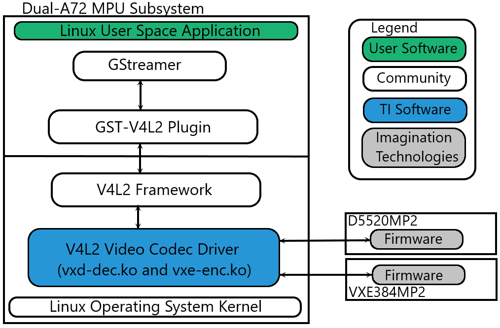
Fig. 3.5 CODEC Software Stack
3.7.4.2. Linux Kernel Drivers
TI-Provided V4L2 Drivers for Multimedia
Video4Linux version 2 (V4L2) is an open source framework that provides a media interface to all Linux-based applications. V4L2 is a collection of device drivers and an API for supporting realtime video capture and video memory-to-memory operations on Linux systems.
Video encode and decode using the ENCODER and DECODER hardware, respectively, are enabled as V4L2 drivers. The V4L2 is integrated with the ENCODER and DECODER drivers by a thin layer that implements the required V4L2 ioctls. Furthermore, this layer is also responsible for translating the incoming V4L2 data structures to those understood by the ENCODER/DECODER.
3.7.4.2.1. V4L2 Video Decoder
The V4L2 video decoder driver is a memory-to-memory device that receives the encoded data on its “output” stream and generates the decoded data to its “capture” stream. The module name is “vxd-dec.ko”.
Codec Support
The V4L2 decoder driver supports receiving the following encoded bitstream formats on its “output” stream:
V4L2_PIX_FMT_H264
V4L2_PIX_FMT_HEVC
V4L2_PIX_FMT_MJPEG
Color Format Support
The DECODER supports outputting several color formats. There is no color conversion performed. The selected color format should be the same as the native color format of the encoded stream. The V4L2 decoder driver supports several standard V4L2 color formats, plus two custom color formats. The formats supported are:
Standard Formats:
V4L2_PIX_FMT_NV12
V4L2_PIX_FMT_NV16
V4L2_PIX_FMT_YUV420M
V4L2_PIX_FMT_YUV422M
Custom Formats:
V4L2_PIX_FMT_TI1210 (NV12 10-bit)
V4L2_PIX_FMT_TI1610 (NV16 10-bit)
Note
Formats with an “M” at the end of their name are multi-planar formats, meaning that the planes are non-contiguous in memory.
The following table shows the native color format support for each of the supported codecs:
Codec |
Supported Color Format |
H.264 |
V4L2_PIX_FMT_NV12 V4L2_PIX_FMT_NV16 V4L2_PIX_FMT_TI1210 V4L2_PIX_FMT_TI1610 |
HEVC/H.265 |
V4L2_PIX_FMT_NV12 V4L2_PIX_FMT_NV16 V4L2_PIX_FMT_TI1210 V4L2_PIX_FMT_TI1610 |
MJPEG |
V4L2_PIX_FMT_YUV420M V4L2_PIX_FMT_YUV422M |
3.7.4.2.2. V4L2 Video Encoder
The V4L2 video encoder driver is a memory-to-memory device that receives the raw frame data on its “output” stream and generates the encoded data to its “capture” stream. The module name is “vxe-enc.ko”.
Codec Support
The V4L2 encoder driver supports encoding to the following encoded bitstream formats on its “capture” stream:
V4L2_PIX_FMT_H264
Color Format Support
The V4L2 encoder driver supports encoding of the following color formats for the raw data “output” stream:
V4L2_PIX_FMT_NV12
Configurable Controls
The V4L2 encoder driver has the following configurable controls:
Ctrl |
Min |
Max |
Step |
Default |
V4L2_CID_MPEG_VIDEO_GOP_SIZE |
1 |
7200 |
1 |
1800 |
V4L2_CID_MPEG_VIDEO_BITRATE |
50000 |
100000000 |
1 |
500000 |
V4L2_CID_MPEG_VIDEO_H264_I_PERIOD |
1 |
600 |
1 |
3600 |
Note
The controls should be set before calling VIDIOC_S_FMT.
The following table gives recommended values for bitrate based on resolution and frame type:
Resolution |
Bitrate for I-frame Only sequence |
Bitrate for IPP sequence |
QCIF (176x144) |
1000000 |
500000 |
CIF (352x288) |
2000000 |
1000000 |
VGA (640x480) |
6000000 |
4000000 |
HD (1280x720) |
12000000 |
7000000 |
Full HD (1920x1080) |
15000000 |
10000000 |
The encoder driver is using standard v4l2 mechanisms for configuring the various parameters for profile, level, bitrate, tools, gop structure, etc. This means the user can use ‘v4l2-ctl -L’ to list all the available controls. Then from gstreamer, use the extra-controls=s,<ctrl_name>=<value> syntax to actually set them as part of the v4l2h264enc parameters.
However, it is important to note that while profile and level can be set using this method, GStreamer 1.20.5 always sets profile and level to baseline/level_1.
To overcome this, don’t set profile/level with extra-controls, use the caps of the video stream to set profile and level like this between the encoder and the next element.
! 'video/x-h264,profile=(string)main,level=(string)4.0' !
Please see section Running a GStreamer pipeline for example pipelines that properly set the additional controls in Gstreamer.
3.7.4.3. GStreamer Plugins for Multimedia
Open Source GStreamer Overview
GStreamer is an open source framework that simplifies the development of multimedia applications, such as media players and capture encoders. It encapsulates existing multimedia software components, such as codecs, filters, and platform-specific I/O operations, by using a standard interface and providing a uniform framework across applications.
The modular nature of GStreamer facilitates the addition of new functionality, transparent inclusion of component advancements and allows for flexibility in application development and testing. Processing nodes are implemented via GStreamer plugins with several sink and/or source pads. Many plugins are running as ARM software implementations, but for more complex SoCs, certain functions are better executed on hardware-accelerated IPs like D5520MP2 (DECODER) and VXE384MP2 (ENCODER).
GStreamer is a multimedia framework based on data flow paradigm. It allows easy plugin registration just by deploying new shared objects to the /usr/lib/gstreamer-1.0 folder. The shared libraries in this folder are scanned for reserved data structures identifying capabilities of individual plugins. Individual processing nodes can be interconnected as a pipeline at run-time, creating complex topologies. Node interfacing compatibility is verified before the pipeline is started.
GStreamer brings a lot of value-added features to Processor SDK Linux J721e, including audio encoding/decoding, audio/video synchronization, and interaction with a wide variety of open source plugins (muxers, demuxers, codecs, and filters). New GStreamer features are continuously being added, and the core libraries are actively supported by participants in the GStreamer community. Additional information about the GStreamer framework is available on the GStreamer project site: http://gstreamer.freedesktop.org/.
Hardware-Accelerated GStreamer Plugins
One benefit of using GStreamer as a multimedia framework is that the core libraries already build and run on ARM Linux. Only a GStreamer plugin is required to enable additional hardware features on TI’s embedded processors with both ARM and hardware accelerators for multimedia. The open source GStreamer plugins provide elements for GStreamer pipelines that enable the use of hardware-accelerated video decoding through the V4L2 GStreamer plugin.
Below is a list of GStreamer plugins that utilize the hardware-accelerated video decoding in the J721E.
DECODER
v4l2h264dec
v4l2h265dec
v4l2jpegdec
ENCODER
v4l2h264enc
3.7.5. GStreamer Pipelines
Visual Representation of Typical GStreamer Pipelines
A typical GStreamer pipeline starts with one or more source elements, uses zero or more filter elements, and ends in a sink or multiple sinks.
This section provides visual representation of one typical GStreamer pipeline: multimedia decoding and playout.
Decode Pipeline
The example pipeline shown in the figure GStreamer Decode Playout demonstrates the demuxing and playback of a transport stream. The input is first read using the source element, and then processed by GStreamer playbin2 (Player Bin 2). To use playbin2 in the pipeline, we use the playbin element (as shown in the figure below). Inside playbin2, demuxer first demuxes the stream into its audio and video stream components.
The video stream is then queued and sent to V4L2 GStreamer plugin for decoding. Finally, it is sent to a video sink to display the decoded video on the screen. The audio stream is queued and then decoded by the ARM audio GStreamer plugin, and then reaches its destination at the alsasink element to play the decoded audio.
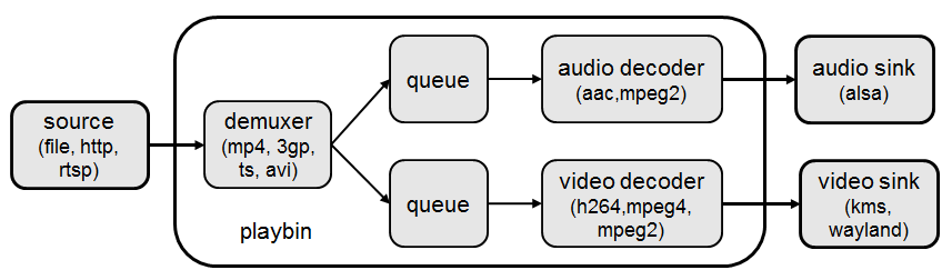
Fig. 3.6 GStreamer Decode Playout
3.7.5.1. Running a GStreamer pipeline
GStreamer pipelines can also run from the command line. In order to do so, exit Weston by pressing Ctrl-Alt-Backspace from the keyboard which connects to the EVM. Then, if the LCD screen stays in “Please wait…”, press Ctrl-Alt-F1 to go to the command line on the LCD console. After that, the command line can be used from serial console, SSH console, or LCD console.
One can run an audio video file using the GStreamer playbin from the console. Currently, the supported Audio/video sink is kmssink, waylandsink and alsassink.
Note
playbin is currently supported only with kmssink and only for NV12 output.
kmssink:
  target #  gst-launch-1.0 playbin uri=file:///<path_to_file> video-sink=kmssink audio-sink=alsasink
One can also run an audio video file without playbin. This is required for decode to any sink except kmssink due to the need to use the video format filter, which can not be used with playbin. The following pipelines show how to playback to kmssink and waylandsink without playbin.
kmssink (video only playback):
  target #  gst-launch-1.0 filesrc location=/<path_to_file> ! qtdemux ! h264parse ! v4l2h264dec ! video/x-raw,format=NV12 ! kmssink
kmssink (audio + video playback):
  target #  gst-launch-1.0 filesrc location=/<path_to_file> ! qtdemux name=demux \
            demux.video_0 ! queue ! h264parse ! v4l2h264dec ! video/x-raw,format=NV12 ! kmssink \
            demux.audio_0 ! queue ! decodebin ! alsasink
The following pipelines show playback to waylandsink. Please refer Wayland/Weston to start Weston before running the pipelines.
waylandsink (video only playback):
  target #  gst-launch-1.0 filesrc location=/<path_to_file> ! qtdemux ! h264parse ! v4l2h264dec ! video/x-raw,format=NV12 ! waylandsink
waylandsink (audio + video playback):
  target #  gst-launch-1.0 filesrc location=/<path_to_file> ! qtdemux name=demux \
            demux.video_0 ! queue ! h264parse ! v4l2h264dec ! video/x-raw,format=NV12 ! waylandsink \
            demux.audio_0 ! queue ! decodebin ! alsasink
Note
The V4L2 Plugin (and TI V4L2 Video Decode driver) will not select the native color format on its own. The video format filter MUST be used to ensure proper decoding. The required filter is highlighted in the below example pipeline. The format can be changed according to the input stream:
gst-launch-1.0 ! filesrc location=/<path_to_file> ! qtdemux ! h264parse ! v4l2h264dec ! video/x-raw,format=NV12 ! waylandsink
If the native format is not supported by the sink, then a color converter plugin will need to be used in the pipeline.
playbin is currently supported ONLY with kmssink and ONLY for NV12 format.
For full list of limitations, see Limitations of GStreamer Plugins.
The following pipelines show examples of using the v4l2h265dec and v4l2jpegdec elements.
HEVC/H.265 video playback to waylandsink
  target #  gst-launch-1.0 filesrc location=/<path_to_file> ! qtdemux ! h265parse ! v4l2h265dec ! video/x-raw,format=NV12 ! waylandsink
MJPEG video playback to waylandsink
  target #  gst-launch-1.0 filesrc location=/<path_to_file> ! qtdemux ! jpegparse ! v4l2jpegdec ! video/x-raw,format=I420 ! videoconvert ! video/x-raw,format=NV12 ! waylandsink
Scaling of the decoded video to fit the display with kmssink can be achieved by selecting a kms plane with scaling support.
To enumerate all the connector IDs and plane IDs, modetest can be used:
  target #  modetest -M tidss -p

kmssink playback using VID plane that supports display scaling:
  target #  gst-launch-1.0 playbin uri=file:///<path_to_file> video-sink="kmssink plane-id=41" audio-sink=alsasink

Or
  target #  gst-launch-1.0 filesrc location=/<path_to_file> ! qtdemux ! h264parse ! v4l2h264dec ! video/x-raw,format=NV12 ! kmssink plane-id=41
The following pipeline shows example of using the v4l2h264enc element.
H.264 video encoding to filesink
   target #  gst-launch-1.0 filesrc location=/<path_to_file> rawvideoparse width=1280 height=720 framerate=30/1 format=23 ! v4l2h264enc ! filesink location=/<path_to_file>
As previously mentioned in Linux Kernel Drivers, the encoder can be configured with additional controls. The following pipelines provided some insight on how these configurations can be done.
Main Profile, level 4, and CABAC disabled
   target # gst-launch-1.0 videotestsrc num_buffers=1000 ! capssetter caps="video/x-raw,width=1920,height=1072,framerate=25/1,format=NV12" ! \
            v4l2h264enc extra-controls="s,video_bitrate=1000000,h264_8x8_transform_enable=false,\
            h264_entropy_mode=false,max_number_of_reference_pics=1" ! \
            'video/x-h264,profile=(string)main,level=(string)4' ! filesink location=test.264
High profile, level 5.1, with CABAC and 8x8 transform enabled
   target # gst-launch-1.0 videotestsrc num_buffers=1000 ! capssetter caps="video/x-raw,width=1920,height=1072,framerate=25/1,format=NV12" ! \
            v4l2h264enc extra-controls="s,video_bitrate=1000000,h264_8x8_transform_enable=true,\
            h264_entropy_mode=true,max_number_of_reference_pics=1" ! 'video/x-h264,profile=(string)main,level=(string)5.1' ! filesink location=test.264
Constrained baseline, level 2.1
   target # gst-launch-1.0 videotestsrc num_buffers=1000 ! capssetter caps="video/x-raw,width=320,height=240,framerate=20/1,format=NV12" ! \
            v4l2h264enc extra-controls="s,video_bitrate=64000,h264_8x8_transform_enable=false, h264_entropy_mode=0,max_number_of_reference_pics=1" ! \
            'video/x-h264,profile=(string)baseline,level=(string)2.1' ! filesink location=test.264
Note
If an incorrect combination of tools is used, or a bitrate/num_ref_frames more than the requested level can support, then the driver WILL override the configuration that was scpecified. By specifying these settings, the user is hinting to the driver what is desired, but the driver inevitably makes the final decision.
Furthermore, controls have been added to give the user the ability to customize the memory configuration in the driver. The default configuration is to adhere to the H.264 spec while simultaneously achieving max performance as per IMG hardware. However, not every stream will need to use the same amount of Decoded Picture Buffers (DPB) - buffers that are used to hold the output from a video decode operation. Buffers found in the DPB list are used for reference for future frames. The stream in use may be configured in a way that only one reference frame is needed. In this case, the default configuration is using more memory than necessary.
To revert the driver back to previous version that only uses 1 reference frame, see below gstreamer pipeline. This pipeline will result in the driver communicating to the firmware that only 1 reference frame should be retained during decode proces.
Use 1 Reference Frame for Decode
target # gst-launch-1.0 filesrc location=<filename.264> ! h264parse ! v4l2h264dec extra-controls=”s,max_dec_frame_buffering=1” ! waylandsink
Note
This might decrease the display latency if the stream does not depend on more than a single reference frame, but it will make the driver less compliant with the H.264 specification.
The algorithm to calculate the number of buffers is now as follows.
num_ref_frames + ((num_cores * slots_per_core) - 1) + display_pipeline_length
Note
num_cores and slots_per_core are constants set in the driver that correspond to the hardware pipelines on the DECODER. These values can be changed, but it is not recommened as it could lead to performance issues.
The driver now allows for complete configuration of this algorithm by exposing these four new controls to the user.
max_dec_frame_buffering:   min=0 max=16 step=1 default=0 value=0
display_pipeline_size:     min=0 max=6 step=1 default=3 value=3
img_extra_decode_buffers:  min=-1 max=3 step=1 default=-1 value=-1
override_spec_dpb_buffers: min=-1 max=16 step=1 default=-1 value=-1
Note
The combination of override_spec_dpb_buffers + img_extra_decode_buffers + display_pipeline_length will translate to the total number of buffer used by the driver to perform decode.
If override_spec_dpb_buffers is set to -1, then the driver will base the number of DPBs using the algorithm supplied in the H.264 specification based on profile and level. Setting img_extra_decode_buffers will overwrite the ((num_cores * slots_per_core) - 1) portion of buffer allocation algorithm.
The following pipelines highlight how these controls can be used to control memory allocation in the driver.
Remove additional buffers allocated due to cores present on DECODER
target # gst-launch-1.0 filesrc location=<filename.264> ! h264parse ! v4l2h264dec
extra-controls=”s,max_dec_frame_buffering=0,display_pipeline_size=2,img_extra_decode_buffers=0” ! waylandsink
Hardcode number of reference frames used
target # gst-launch-1.0 filesrc location=<filename.264> ! h264parse ! v4l2h264dec
extra-controls=”s,max_dec_frame_buffering=0,display_pipeline_size=2,img_extra_decode_buffers=0, override_spec_dpb_buffers=2” ! kmssink
Note
Keep in mind that while this allows for complete control, it is important to understand that changing these values can negatively impact decode performance while reducing memory consumption. It is best to trial different configurations and select what is best for the use case if reducing memory consumption is desired.
All external controls supported by Encoder and Decoder can be seen using below command.
Encoder: v4l2-ctl -d 1 -l
Decoder: v4l2-ctl -d 0 -l
3.7.5.2. Limitations of GStreamer Plugins
Limitations of GStreamer Plugins
GStreamer V4L2 plugin decoder elements need video filter (video/x-raw,format=<format>) to select the native color format for decoding.
playbin is supported ONLY with kmssink and ONLY with NV12 format due to need for video filter with other sinks.
3.7.5.3. GStreamer Plugin Internals
V4L2 GStreamer Plugin Support
Each V4L2 decode element has one sink pad and one src pad. The sink pad is for receiving the encoded bitstream, and the src pad is for outputting the raw video data.
Element Src and Sink Pads
The following table gives the format support for the sink and src pads for each supported element.
Element |
Sink Pad Format |
Src Pad Format |
v4l2h264dec |
H.264 |
NV12 NV16 |
v4l2h265dec |
HEVC/H.265 |
NV12 NV16 |
v4l2jpegdec |
MJPEG |
I420 Y42B |
Note
No color conversion is performed in the plugin or V4L2 drivers. The color format selected should be that of the native color format of the encoded bitstream.
To select the appropriate color format, it is important to provide the color format filter to the GStreamer pipeline. See Running a GStreamer pipeline for more information on how to provide this filter. Example:
gst-launch-1.0 filesrc location=<file_location> ! h264parse ! v4l2h264dec ! video/x-raw,format=NV12 ! kmssink
The v4l2 decode driver supports some custom 10-bit color formats, but that support is not available at GStreamer plugin side.
For full list of limitations, see Limitations of GStreamer Plugins.
Inspecting an Element
To get the full information about an element, the gst-inspect-1.0 utility can be used on the target. For example:
target #  gst-inspect-1.0 v4l2h264dec
target #  gst-inspect-1.0 v4l2h264enc
Note
gst-inspect-1.0 will show that all color formats are available for every element. However, not all color formats are supported by every element. The table here summarizes the actual support per element.
Buffer Flow Considerations
The V4L2 GStreamer Plugin provides the ability to either allocate its own buffers, or import buffers from a downstream plugin such as kmssink or waylandsink. This buffer io-mode can be selected using the property “capture-io-mode”. To request the decoder element (and in turn the TI V4L2 decoder driver) to do the allocation, “dmabuf” (GST_V4L2_IO_DMABUF) is used. To request the element to import buffers allocated downstream, “dmabuf-import” (GST_V4L2_IO_DMABUF_IMPORT) is used. By default for the decode elements, GST_V4L2_IO_DMABUF will be selected due to V4L2 decoder driver support for it. An example of using dmabuf-import in a gstreamer pipeline:
With the TI V4L2 Video Decoder Driver, the best latency performance to display is achieved with “dmabuf-import” (GST_V4L2_IO_DMABUF_IMPORT). This feature provides the best performance because internally the V4L2 element will no longer have to copy buffer information the element’s region, to the display region.
3.7.6. Memory Optimisation
3.7.6.1. Decoder Driver Memory Optimisation
To optimise the Decoder driver memory allocation with performance degradation less than 10%. Change the Macro in Makefile as CAPTURE_CONTIG_ALLOC ?=n, and follow the driver rebuild instructions.
drivers/media/platform/vxe-vxd/makefileMake the following change:
-                 CAPTURE_CONTIG_ALLOC ?=y
+                 CAPTURE_CONTIG_ALLOC ?=n
By changing this macro, the memory allocation is switching from using CMA (contiguous memory allocation) to taking advantage of the MMU that is packaged on the DECODER.
3.7.7. Rebuilding and Debugging
3.7.7.1. Rebuilding V4L2 Drivers
If any modification are made to the drivers, they will need to be rebuilt and updated on the device. These drivers are rebuilt by following the standard process for Building TI’s Linux Kernel. Please refer to this page for a more detailed guide in rebuilding modules.
Once built, install the rebuilt module(s) on target filesystem. Copy the new kernel modules to their proper location on board. These locations for decoder and encoder, respectively, can be seen below.
/lib/modules/<version>/kernel/drivers/media/platform/vxe-vxd/vxd-dec.ko
/lib/modules/<version>/kernel/drivers/media/platform/vxe-vxd/vxe-enc.ko
3.7.7.2. Debug Logs
In case additional logs are needed from the V4L2 Encode or Decode drivers, debug tracing can be enabled by rebuilding the module with the appropriate options selected.
V4L2 Decoder Debug Options
DEBUG_DECODER_DRIVER can be set to ‘y’ to enable all the debug tracing in the decoder driver. This should only be used for debugging purposes. To enable it, set DEBUG_DECODER_DRIVER to ‘y’ and rebuild the decoder module following the instructions in Rebuilding V4L2 Drivers.
V4L2 Encoder Debug Options
DEBUG_ENCODER_DRIVER can be set to ‘y’ to enable all the debug tracing in the encoder driver. This should only be used for debugging purposes. To enable it, set DEBUG_ENCODER_DRIVER to ‘y’ and rebuild the encoder module following the instructions in Rebuilding V4L2 Drivers.
3.7.7.3. Latency Profiling
The decode latency of the V4L2 Decoder can be measured at the picture or firmware level. Only one can be enabled at a time.
Decoder Firmware Latency Profiling
To enable firmware latency profiling, follow these steps:
Enable the print in the driver code by modifying the following file:
drivers/media/platform/img/vxe-vxd/decoder/vxd_pvdec.c
Make the following change:
-                 dev_info(dev,
+                 dev_err(dev,
                           "fw decode time is %llu us for msg_id x%0x\n",
Follow the instructions in the section Rebuilding V4L2 Drivers in order to rebuild the module and copy the updated module to the target. The module to copy is vxd-dec.ko.
Collect the logs and look for the traces that look like:
[ 802.626314] img_dec 4300000.video-decoder: fw decode time is 5314 us for msg_id xc60f
Each trace gives the firmware decode time per frame. All numbers are in micro seconds.
Decoder V4L2-level Picture Decode Latency Profiling
To enable V4L2-level picture decode latency profiling, follow these steps:
Enable the print in the driver code by modifying the following file:
drivers/media/platform/img/vxe-vxd/decoder/vxd_v4l2.c
Make the following change:
-                 dev_info(dev,
+                 dev_err(dev,
                          "picture buf decode time is %llu us for buf_map_id 0x%x\n",
Follow the instructions in the section Rebuilding V4L2 Drivers in order to rebuild the module and copy the updated module to the target. The module to copy is vxd-dec.ko.
Collect the logs and look for the traces that look like:
[ 511.316237] img_dec 4300000.video-decoder: picture buf decode time is 9901 us for buf_map_id 0x4000025
Each trace gives the v4l2-level picture decode time per frame. All numbers are in micro seconds.
Note
- Known limitations:
DMA Buf import on encoder works only for 16 byte width and height aligned buffers from the upstream element. For Non 16 byte aligned resolution, the pipeline exits safely with buffer size negotiation error.