Uniflash Debugging

|
|
Prerequisites include following the TI HW design guidelines and reading the Uniflash User Guide.
It is recommended to follow the links below before start debugging.
Please click Next to start identifying the issue

After Uniflash is successfully installed, open Uniflash and get to the main screen. It is advised to enable debug messages. It can be applied from the 'Window -> Preferences'. Under 'Uniflash Preferences', the 'Print out additional debug information for the supported modules' should be checked for full debug messages.


|
Yes
|
|
No
|
Communication with the device over UART is operational. This phase test whether the attached serial flash is properly formatted.
|
Yes
|
|
Not sure
|
Please try to create a file on the device by clicking on ‘Add file’ button, filling the required parameters and resetting the device when prompted. For more information on adding a file please refer to 'Adding a new file to the device' chapter on Uniflash User Guide.
|
Yes
|
|
No
|
Good news.
Your board is fully operational.
There could be several reasons for not being able to program a file:
- Device is not formatted
- Serial flash is not connected (mainly on a custom board, not on TI EVB)
- Device is not powered properly
Please format the board and program the ServicePack. For more information please refer to the appropriate chapters on Uniflash User Guide.
|
Yes
|
|
No
|
It is possible to use one of TI evaluation boards or build your own development board.
|
Custom board
|
|
TI evaluation board (BoosterPack/LaunchPad)
|
|
QFN
|
|
Module
|
Can you please check the followings?
- Serial flash part is powered properly
- SPI lines to the serial flash are connected properly. Make sure MISO and MOSI are not crossed
|
Yes
|
|
No
|
It's important to verify the main power supplies.
- Voltage on VDD_ANA1 should be around 1.9
- Voltage on VDD_DIG1 should be around 1.2
- Voltage on VDD_ANA2 should be around 3.3V
Please refer to the device schematics for the exact pin to probe.
|
Yes
|
|
No
|
Please open a thread on the SimpleLink WiFi CC31xx/CC32xx E2E forum.
http://e2e.ti.com/support/wireless_connectivity/f/968.aspx
On the post please provide the following information:
- Board revision in case it is TI EVB
- Silk label on CC3xxx chipset
- SDK version
- ServicePack version
TI representative should contact you offline for further support.
Since power supplies are all good but Uniflash doesn’t seem to work, it is best to test whether it is possible to work with the device in debug mode, via JTAG lines (and not UART lines).
Please open any project from the SDK that involves interaction with the device (i.e. includes the sl_start() API) using your chosen IDS (CCS, IAR, GDB, other). Compile the project, load it into the device and get to the sl_start() API. Execute this line.
|
Yes
|
|
No
|
Please open a thread on the SimpleLink WiFi CC31xx/CC32xx E2E forum.
http://e2e.ti.com/support/wireless_connectivity/f/968.aspx for further support.
Seems you cannot communicate with the device over UART. It is possible that other utility such as a terminal emulation is holding the same port. If so, please close it and retry.
|
Yes
|
|
No
|
|
Yes
|
|
No
|
There could be several reasons for not being able to communicate with the device:
- COM ports not recognized on Windows Device Manager
- Wrong COM port is picked
- 921,600 baud rate is not supported or not configured
- HW flow control is configured. Should be configured with no flow control
|
Yes
|
|
No
|
|
CC3100
|
|
CC3200
|
|
Yes
|
|
No
|
It seems FTDI installation was not successful. Please reinstall the drivers. The drivers could be found under SDK installation in the following path:
- For CC3100: cc3100-sdk\tools\cc31xx_board_drivers
- For CC3200: cc3200-sdk\tools\cc32xx_board_drivers
|
Yes
|
|
No
|
|
Yes
|
|
No
|
|
CC3100
|
|
CC3200
|
Working with CC3100 BoosterPack, Device Manager should show 2 COM ports. However, in some cases it shows 4 ports. Both use cases are valid but the user needs to know the correct COM port to configure on Uniflash.
In case 2 COM ports are shown, Uniflash should connect to the lower numbered COM port.
In case 4 COM ports are shown, Uniflash should connect to the 3rd numbered COM port. The correct COM port can also be identified with UART string as part of its ‘Location’ value on Device Manager.
|
Yes
|
|
No
|
Working with CC3200 LaunchPad, Device Manager should show a single COM port. However, in some cases it shows 2 ports. Both use cases are valid but the user needs to know the correct COM port to configure on Uniflash.
In case a single COM port is shown, Uniflash should connect to it.
In case 2 COM ports are shown, Uniflash should connect to the higher numbered COM port. The correct COM port can also be identified with UART string as part of its ‘Location’ value on Device Manager.
|
Yes
|
|
No
|
|
Yes
|
|
No
|
|
Yes
|
|
No
|
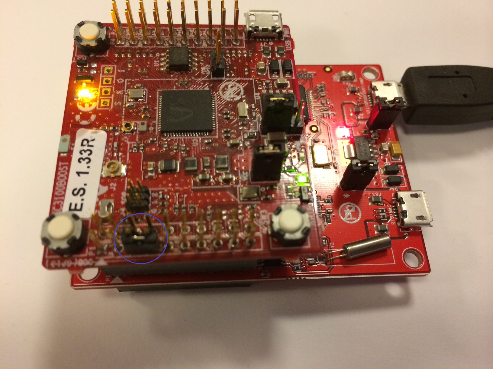
This test is intended to verify that FTDI chipset behaves as expected. In this test a loopback is applied on the correct COM port and characters typed on a terminal emulator connected to the same board should get echoed back.
Following are setup instructions depending on the board type:
- Custom board: user should connect UART TX to UART RX
- CC3100 BoosterPack: on CC3100BOOST board, identify the EM connectors. On P1 column, locate pin #3 and pin #4 with TX and RX labels respectively. Use a jumper to connect both. Attached picture describes the connection.
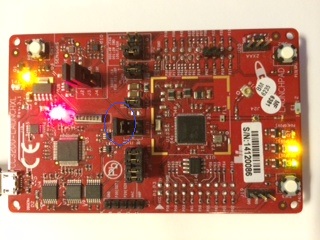
- CC3200 LaunchPad: on LaunchPad board, identify J6 and J7 jumpers. By default these jumpers should be connected on FLASH. Disconnect the two jumpers and connect J6 to J7 as closest to the FTDI chipset. Attached picture describes the connection.
  |
|
Yes
|
|
No
|
|
|

This troubleshooting guide aims to assist Uniflash users identify and potentially fix issues.
This guide is mainly focused on the hardware part and not GUI aspects.
For guidance on how to operate Uniflash and browse through the different options, please refer to Uniflash User Guide on the following link
CC3100\CC3200 SimpleLink™ Wi-Fi® Uniflash User Guide.
Please click Next to start identifying the issue...